- Lines at 3kHz on Bs_MOD_6MHz removed.
- 3kHz source, likely in crates of DSP PR and INJ
- the recovery actions
- Bs_MOD_6mHz cable replug
I refers to the test on the crate 39 switching power supply and to the Moving bump around 3kHz caused by switching power supply of rack 39? too.
I 've a look at the Bs_MOD_6MHz and the Bs_MOD_22MHz
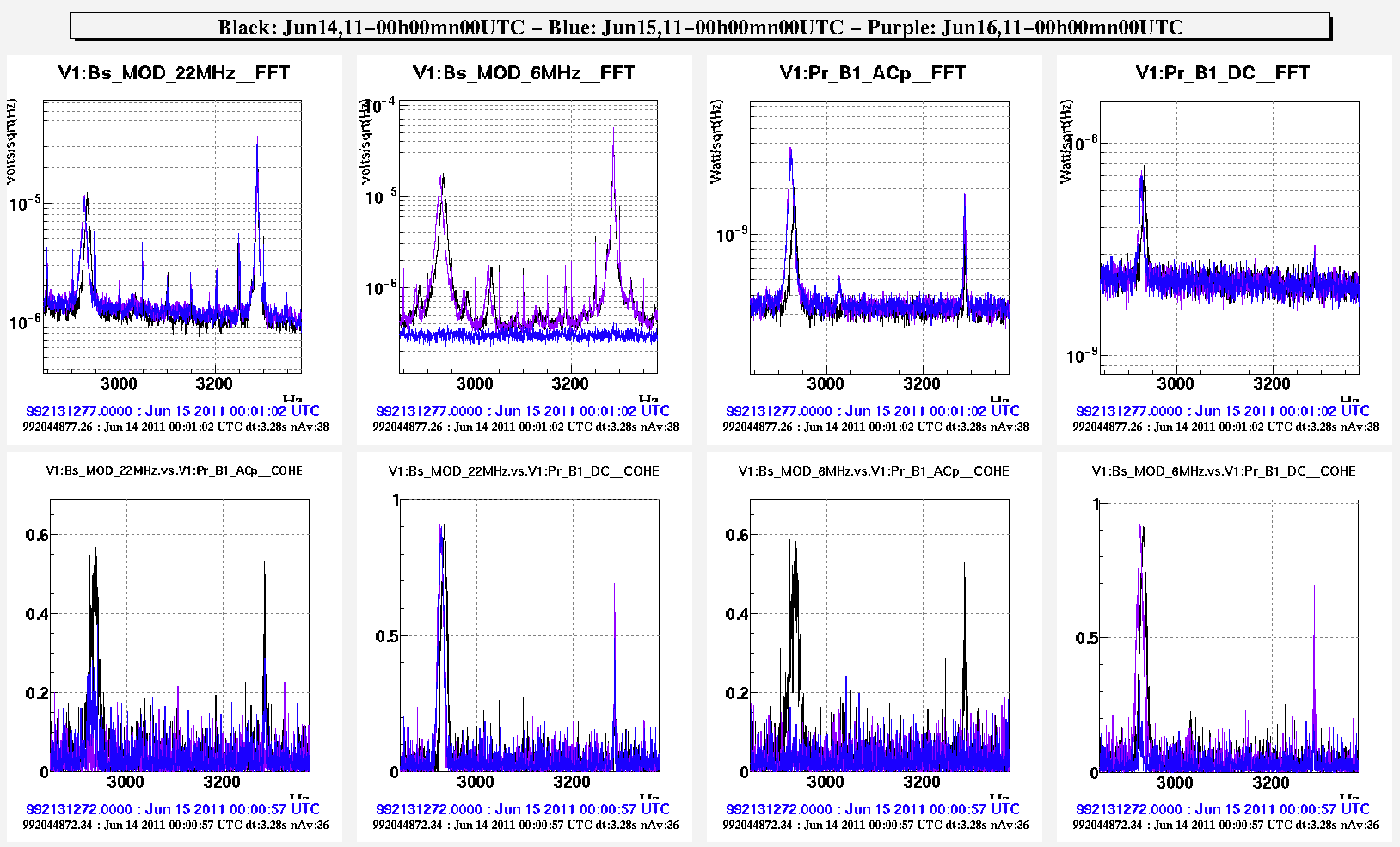
- before the the Bs_MOD_6MHz unplug. at Jun14,11-00h00mn00UTC ()
- after the 3kHz source investigation and its recovery actions at Jun15,11-00h00mn00UTC
- and after the Bs_MOD_6mHz cable replug at Jun16,11-00h00mn00UTC
Today
- the MOD_xxMHz are acquired 2 times: first at 1Hz by a Pisa ADC located the C40 Daq room rack and propagated using BNC cables and a 20KHz with ADC7674 located at the EERooms. They are extracted after the Pocket cell
- the LO 6MHz propagated trough the LO distribution chain is taken from the output of the 6/8 divider
One can see on different plots that:
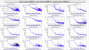
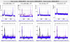
- the noise floor of the Ca_PR_RM_CoilD is reduced after the Jun14,11 afternoon recovery actions(graph 1,2)
- the 2 bumps around 3KHz present on B1_ACp are well visible on Bs_MOD_22MHz, Bs_MOD_6MHz, Ca_{PR,BS)_RM_Coilx and on Pr_B1_DC. They are not present on the Ti_6MHz_Modulus and Ti_6MHz_phase_xx signals meaning that they are not present in the LO signal propagated trough the LO distribution chain (graph 1,2) and extracted after the 6/8 divider.
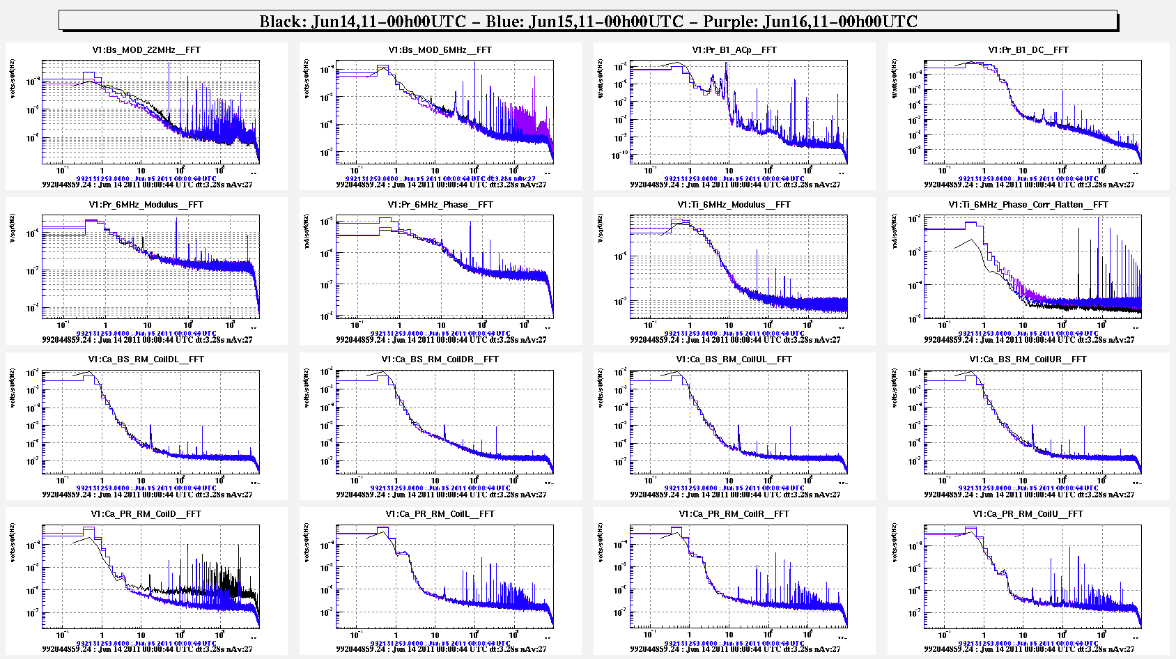
- When the MOD_6MHz 1Hz acquisition cable is disconnected, the Bs_MOD_6MHz is more cleaner after 1KHz and the 3KHz bumps are not present. It 's like the high frequency noise is propagated by the BNC cable from the DAQ room to the Laser LAB. The 3KHz bumps remains present on the Bs_MOD_22MHz, and the Ca_xx_RM_Coils.(graph 1,2)
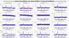
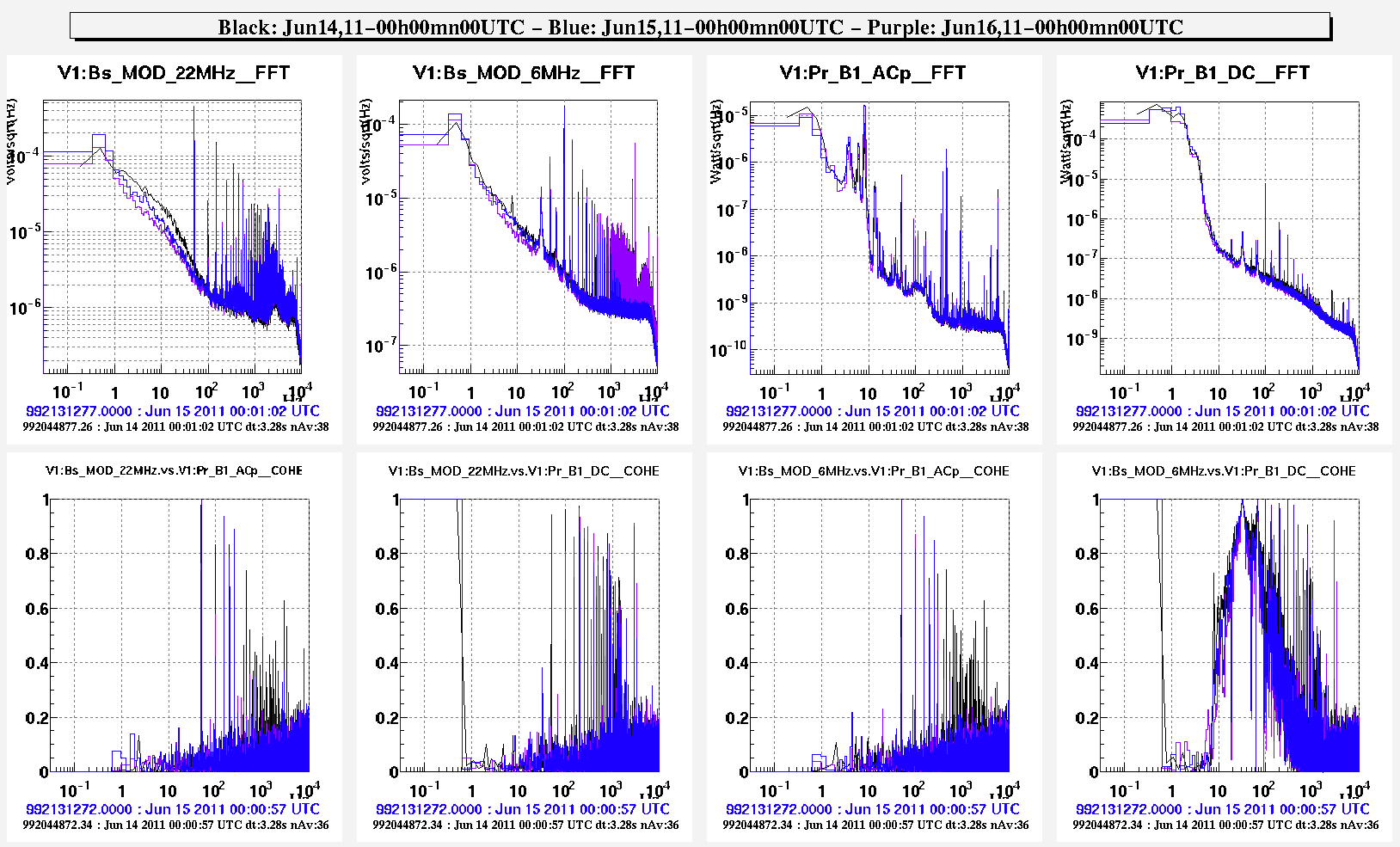
- there is a lot of coherence between Bs_MOD_6MHz and Pr_B1_DC in 10-100Hz region(coherence plots graph 3,4 )
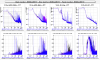
- for the 2 bumps around 3KHz, there is a good coherence between the Bs_MOD_xxMHz and the Pr_B1_ACp and Pr_B1_DC signals graph 3,5)
- After the re-cabling of Bs_MOD_6MHz 1Hz acquisition cable, the 2 bumps comes back in the Bs_MOD_6MHz but there is no coherence with the Pr_B1_ACp while the coherence remains high for Pr_B1_DC.(graph 5)
Next time It could be useful to dis-cable the 2 MOD_xxMHz 1Hz acquisition cables at the same time to see the effect.
For the VDQ group, instead of using the Bs_MOD_xxMHx channel to monitor the 3KHz bumps, the Ca_PR_RM_Coilx channels could be use.
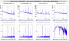
The signal was very clean (no 3kHz lines) as visible in ADC7674 when the Bs_MOD_6MHz was unplugged from Pisa ADC.
This confirm that the 3kHz lines are "fake" (= no present in the Bs_MOD_6MHz).
However there were two lines equally spaced (~18Hz) around 50Hz, both clearly visible in the same signal at the same time; they are indeed real.
This means that the Virgo modulation index could be "modulated" at 32Hz and 68Hz.