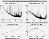
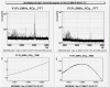
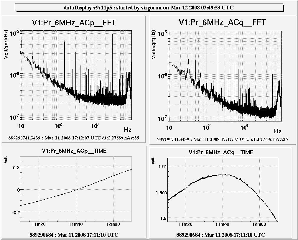
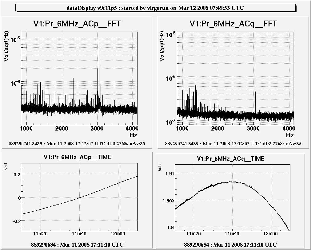
The standard 6MHz local oscilator signal is used as RF input to the demodulation board and a 6MHz reference from the LNFS is used as LO for demodulation. First figure shows the phase noise and amplitude noises measured in this way. The phase/amplitude noise here include all noise arising from the modulation electronics, the LO board and the demodulation board. There is a strange forest of lines above 1kHz which is rather different for phase and amplitude noise (2nd figure).
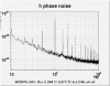
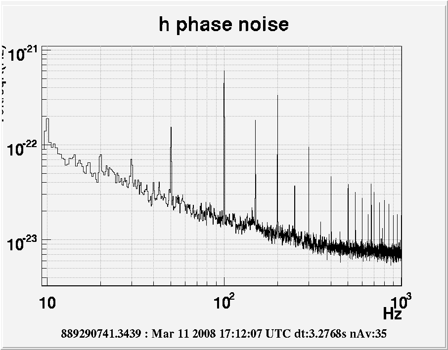
Using this measurement figure 3 shows an upper limit on the expected phase noise (in h). This is an upper limit since at low frequency a large fraction of the modulation noise should cancel in the demodulation process (it is common to the beam and the local oscilator signal) and only demodulation noise should contribute. This noise is safe now but might be a limitation for Virgo+ with monolitic suspensions.
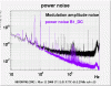
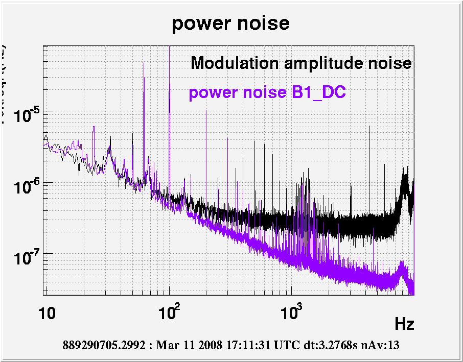
Figure 4 shows the power noise measured now on B1_DC (purple) and the modulation amplitude noise (black). The low frequency matches pretty well, especially the structures at 33, 67 and 133 Hz, the 100 and 200 Hz lines and some lines at high frequency. Above 100 Hz the measurement of modulation amplitude noise is probably limited by readout noise which explains why the floor noise doesn't match with B1_DC.
One can conclude that B1_DC is now completly limited by modulation amplitude noise. Could that be improved?