Reports 1-1 of 1 Clear search Modify search
Environmental Monitoring (Environmental Monitoring)
fiori, schofield, tringali, dattilo, paoletti, d'andrea - 13:14 Monday 16 March 2026 (68882) Print this report
grounding injection test

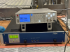
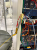
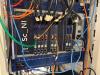
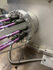
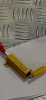
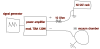
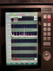
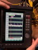
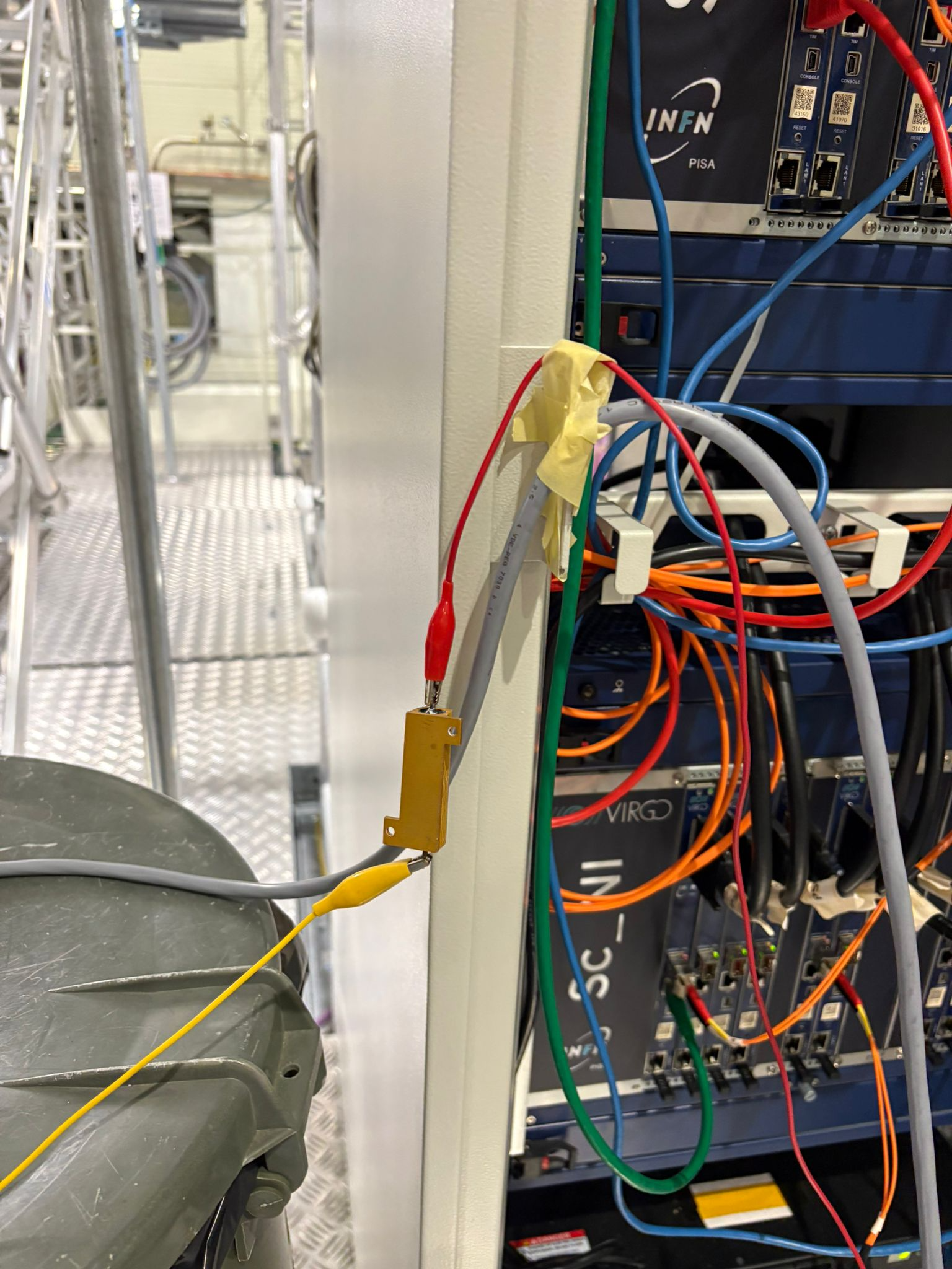
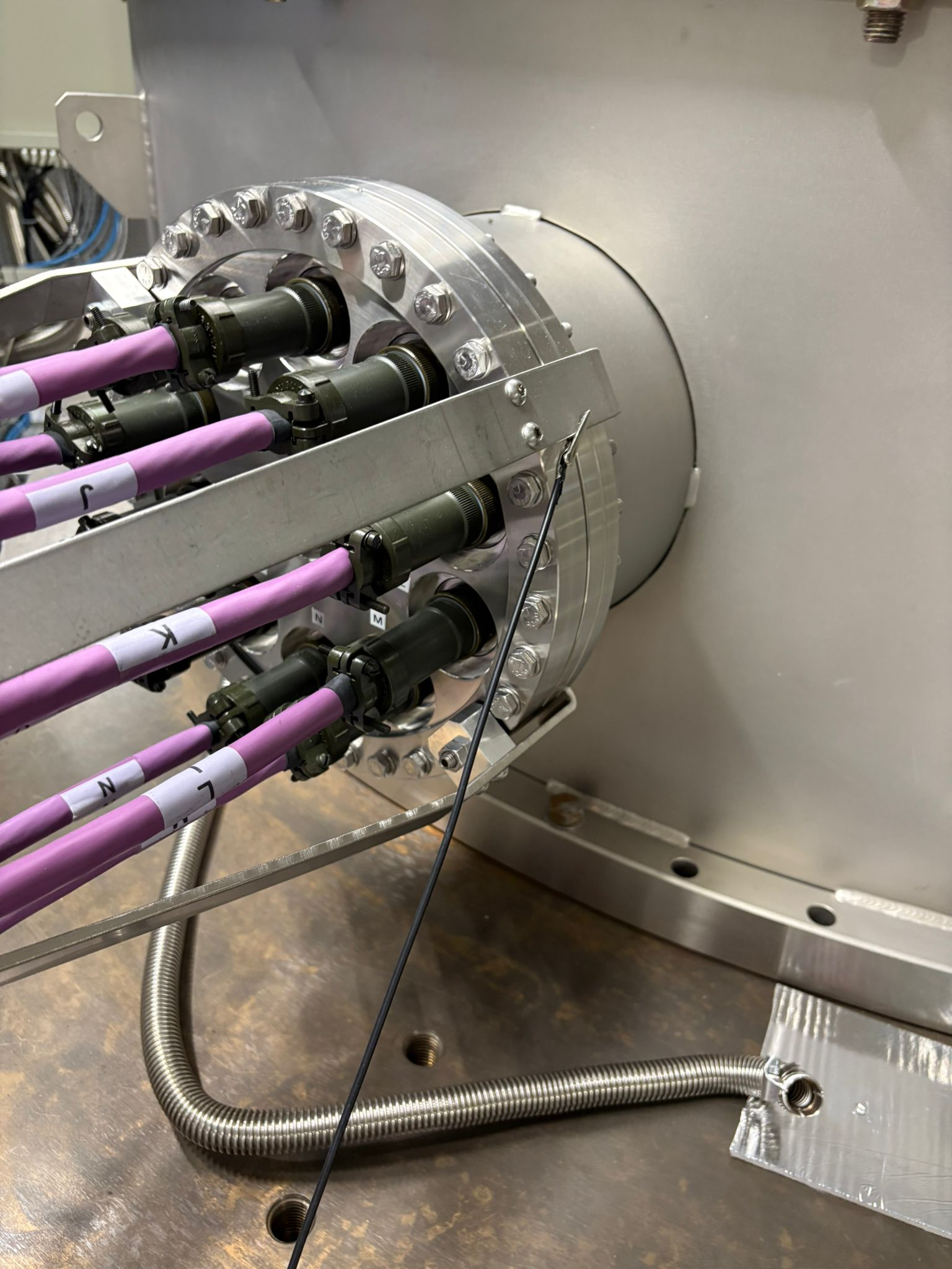
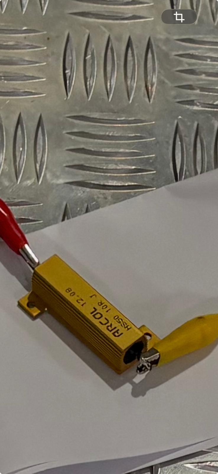
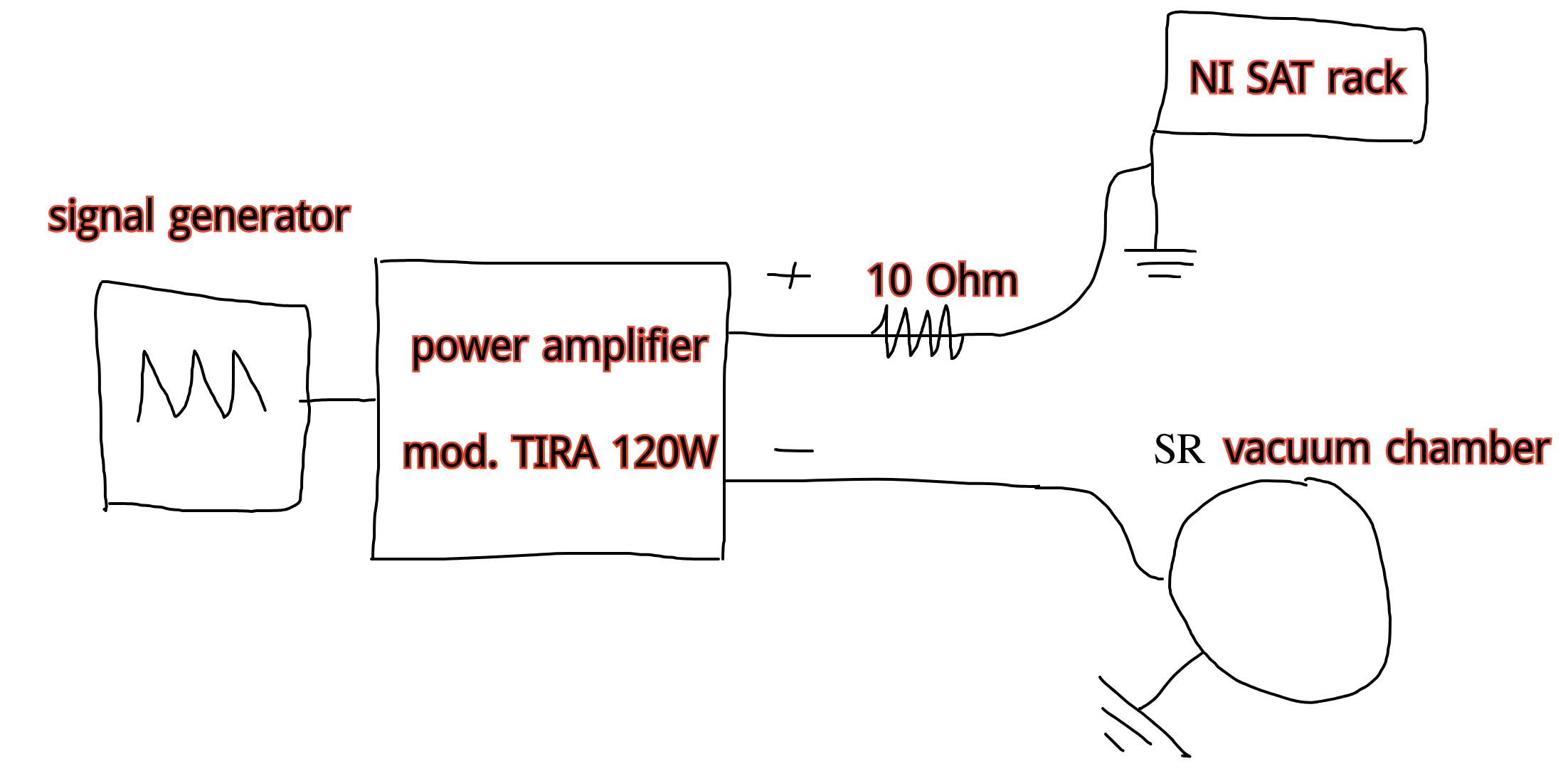
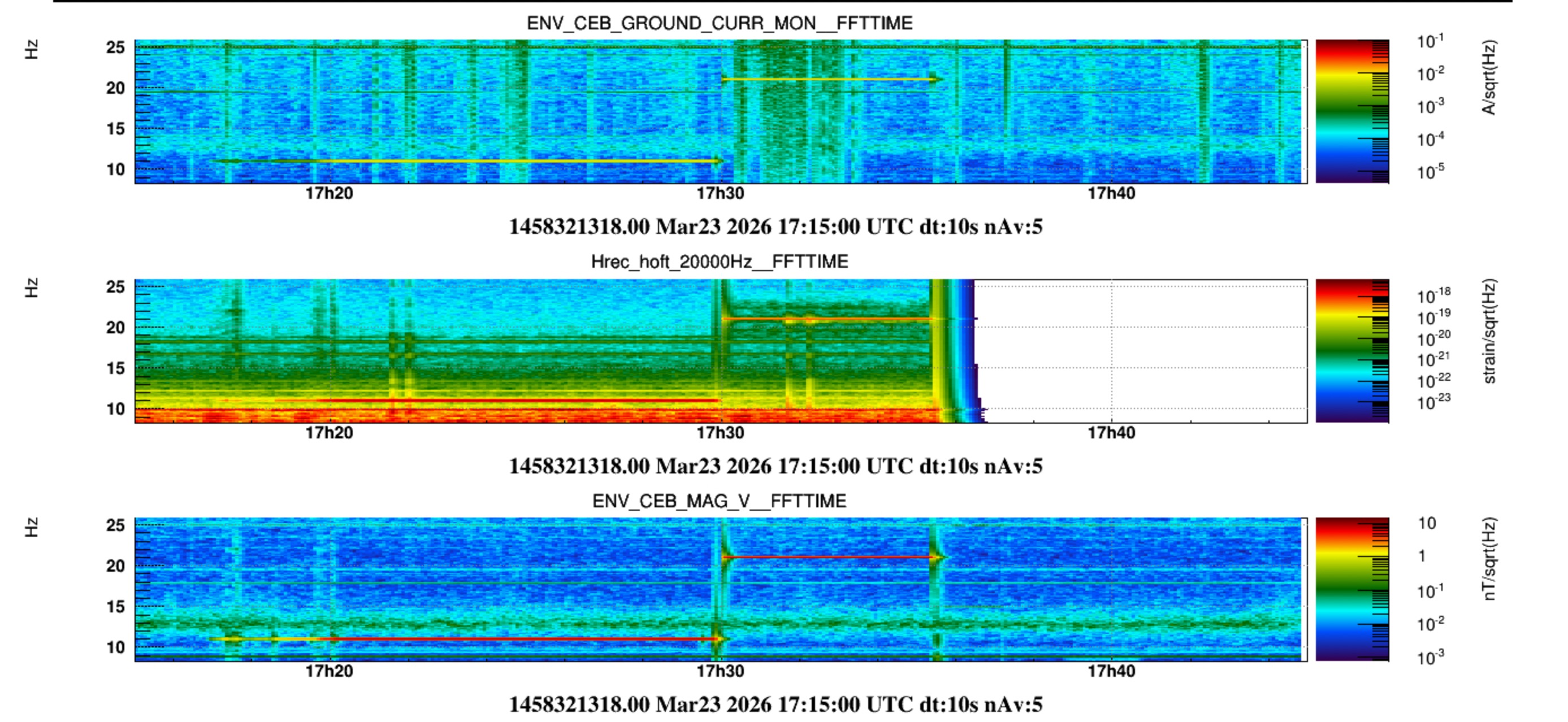
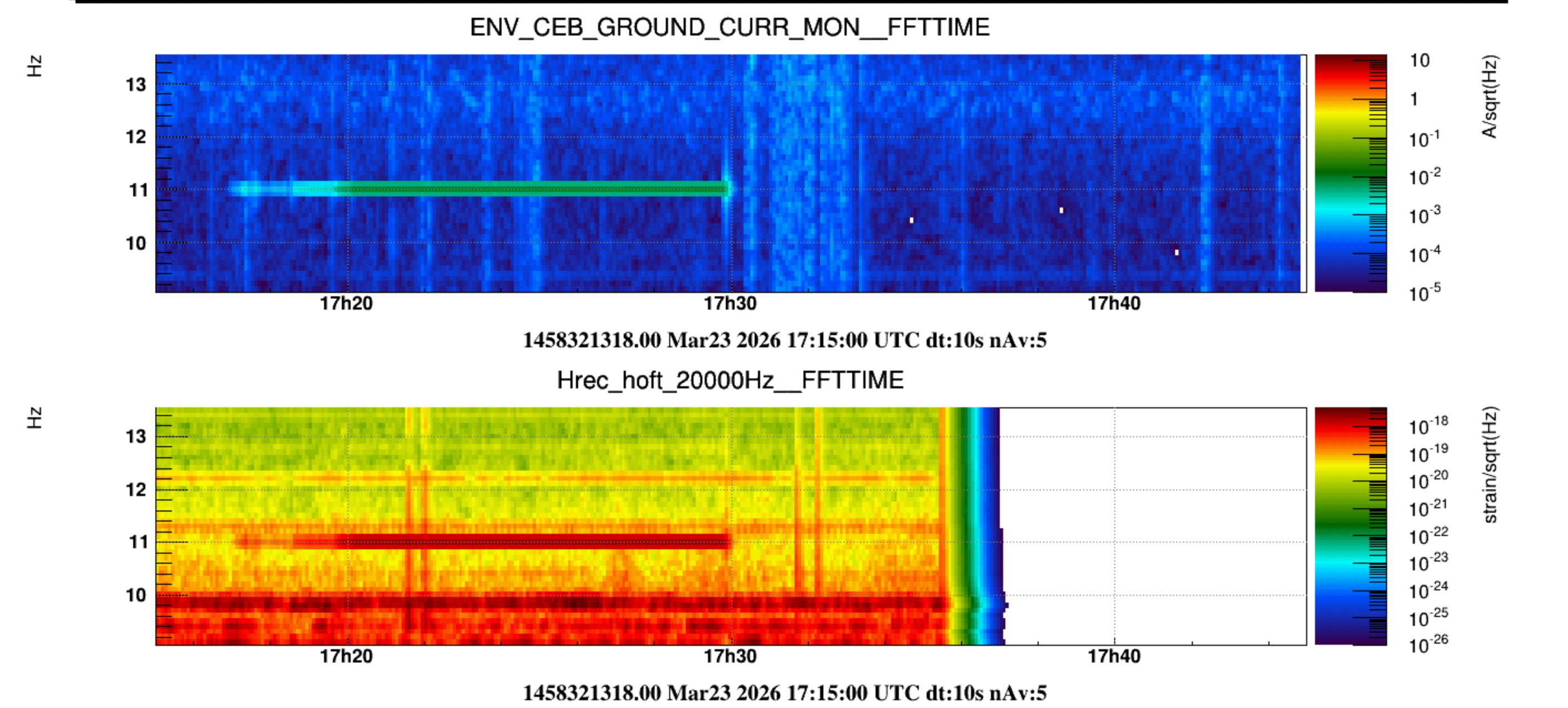
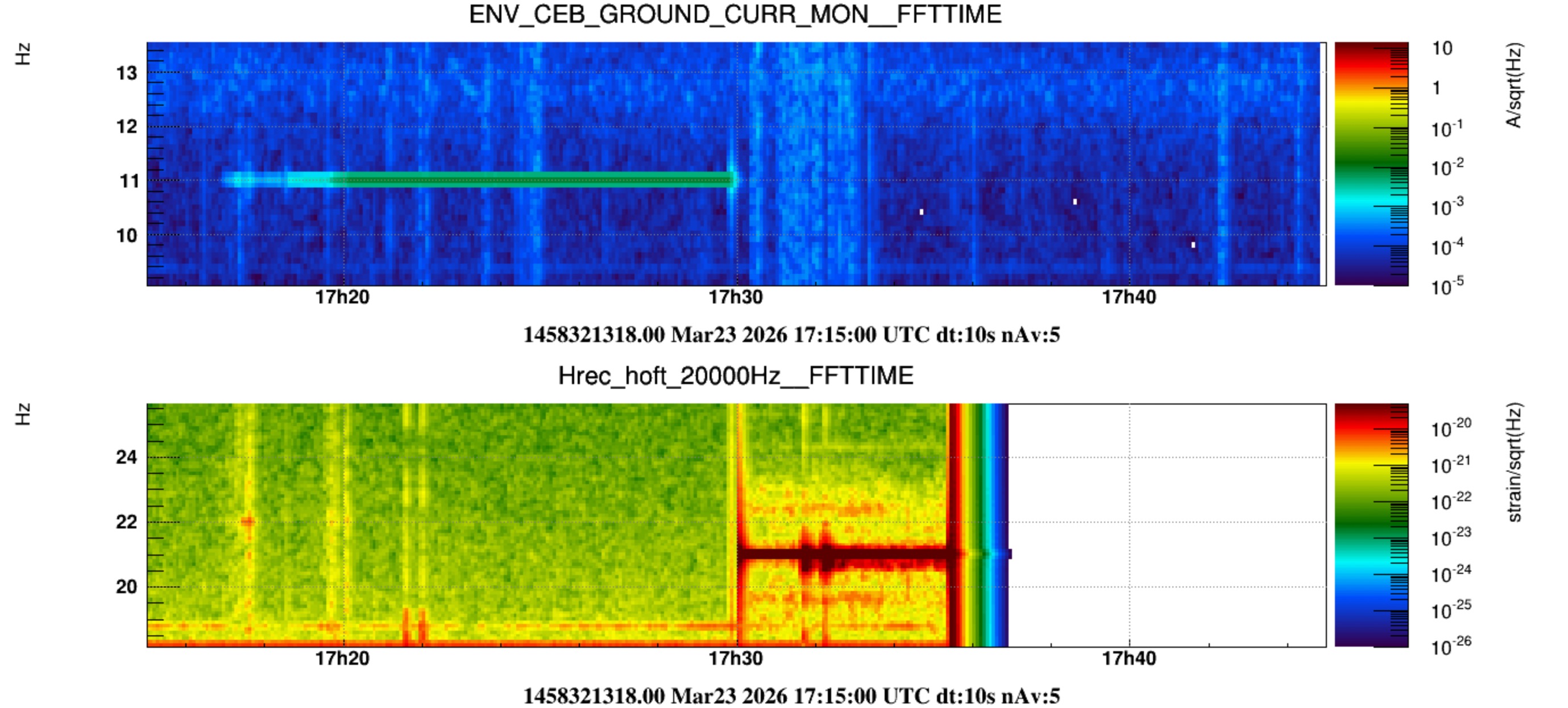
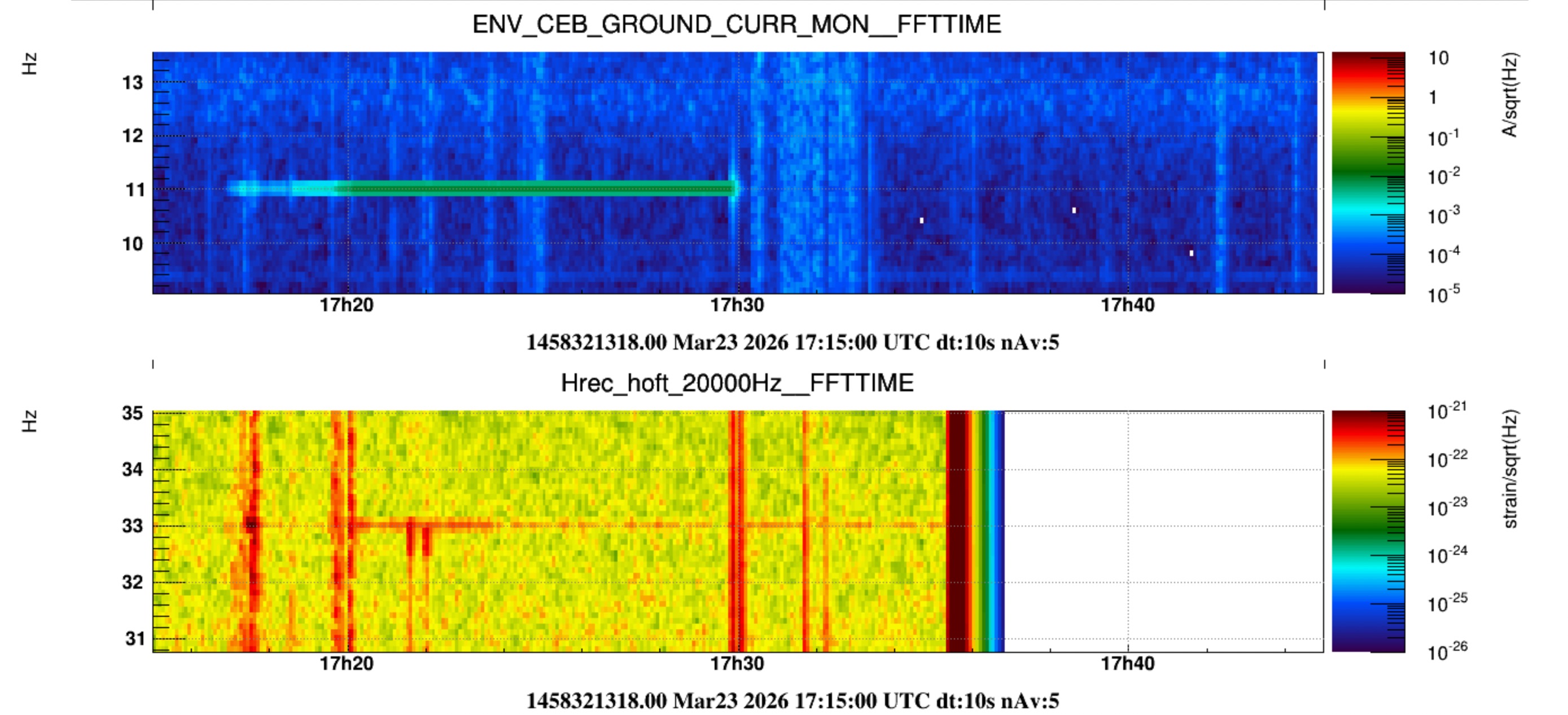
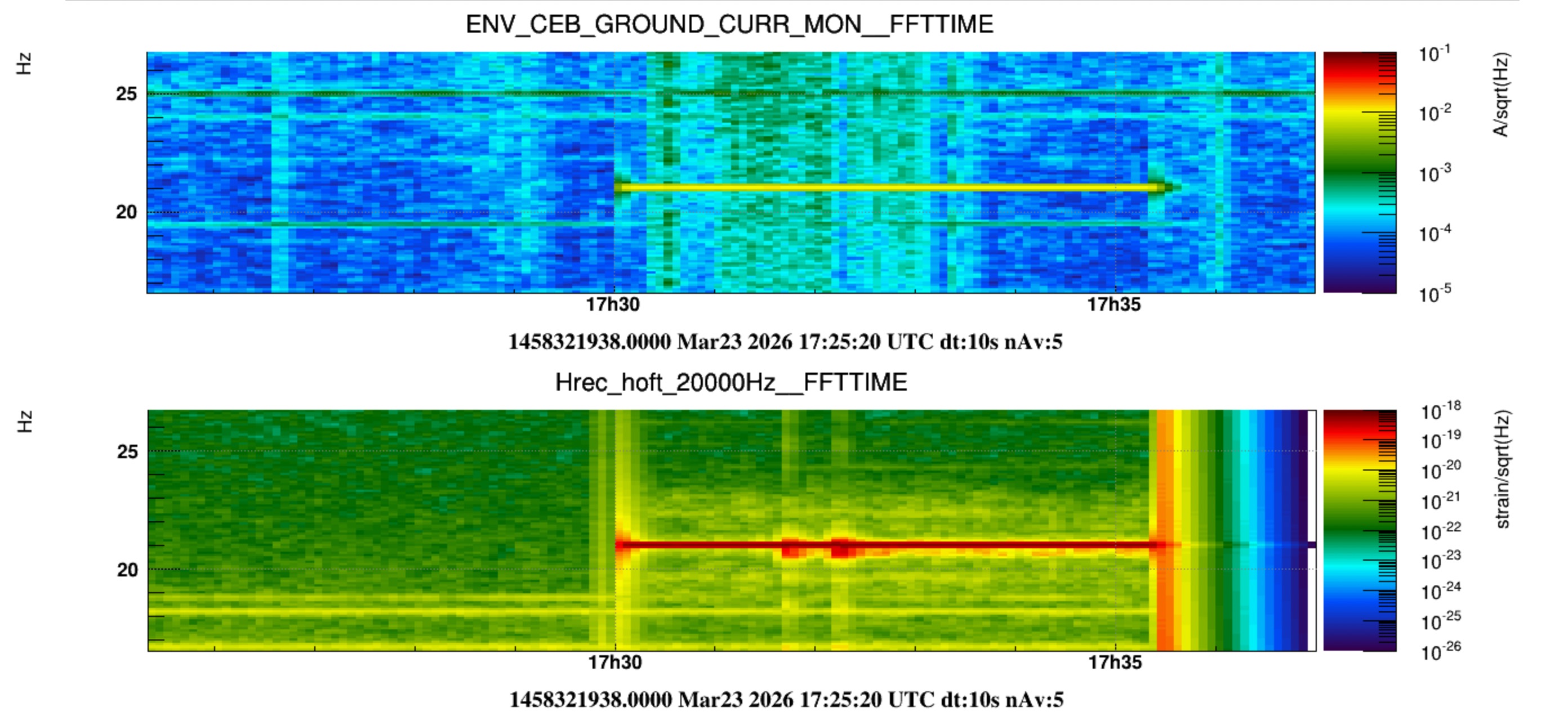
Last Friday (13th March) we installed the ground current injection setup (pictures 1-6) and we tested it without ITF. Figure 7 shows a scheme. The injection is performed between the electrical ground of the NI SAT crate and the SR vacuum chamber. The driving signal was one 11Hz comb (saw-tooth by the Hameg generator) amplified to approx 0.5 A and 5 V  (as read in the display of the TIRA BAA-120W amplifier, and also with one ammeter in series with the resistor). Tips by Robert and Federico: do not exceed 1A, the resistor should not become "hot". Be careful not to swap '+' and '-'. The two ends of the cable out of the amplifier (both black) have been labelled. 

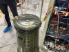
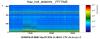
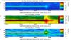
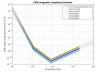
The current clamp sensor (ENV_CEB_GROUND_CURR_MON) is described in this entry: https://logbook.virgo-gw.eu/virgo/?r=68265. It was placed around the cable connecting the ground of all platform racks to the CEB hall main ground copper bar. In turn this copper bar is connected to the CEB main copper bar located in the service room next to the main entrance. Finally the latter bar is connected to the safaty earth, which consists of one external ring with ground rods placed all around CEB.

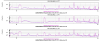
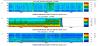
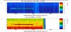
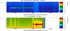
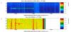
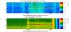
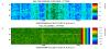
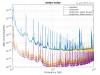
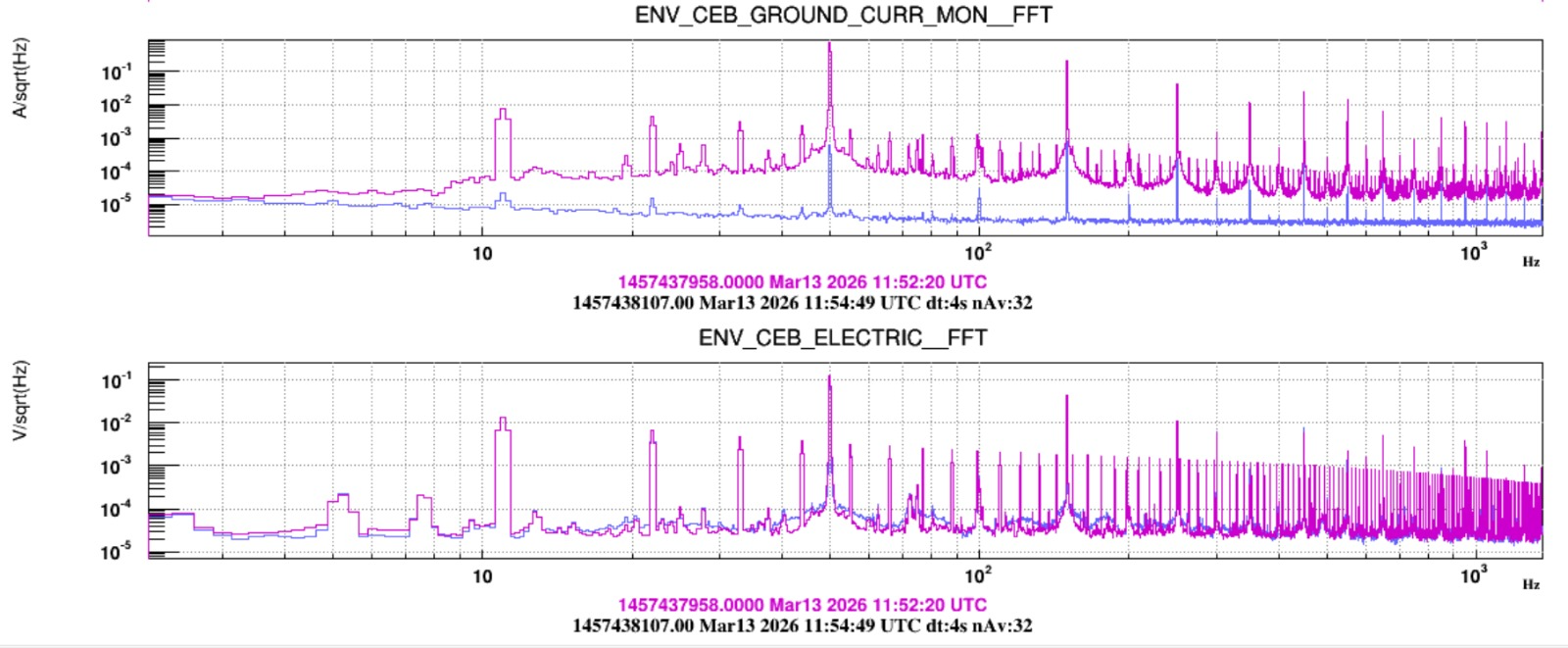
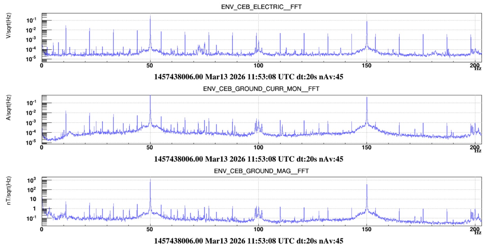
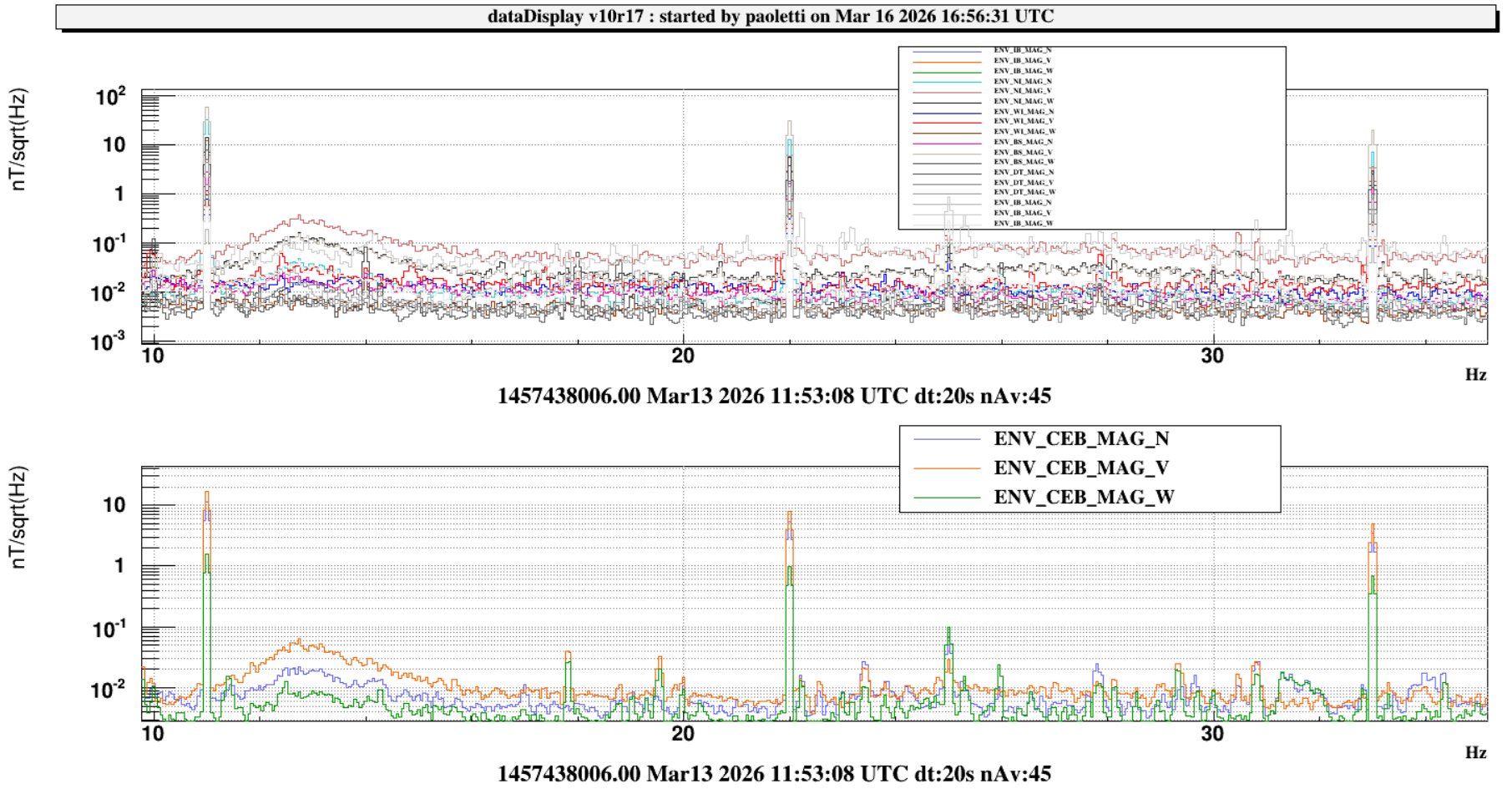
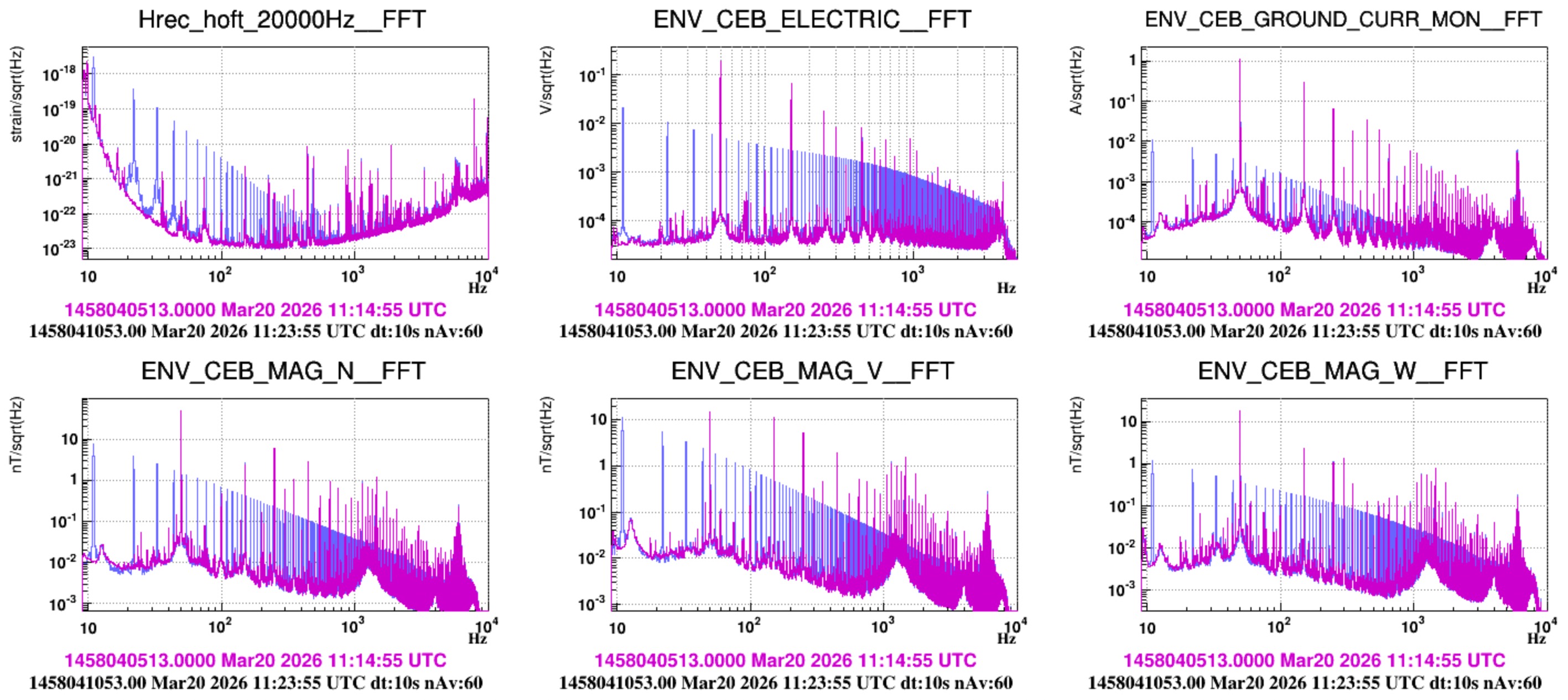
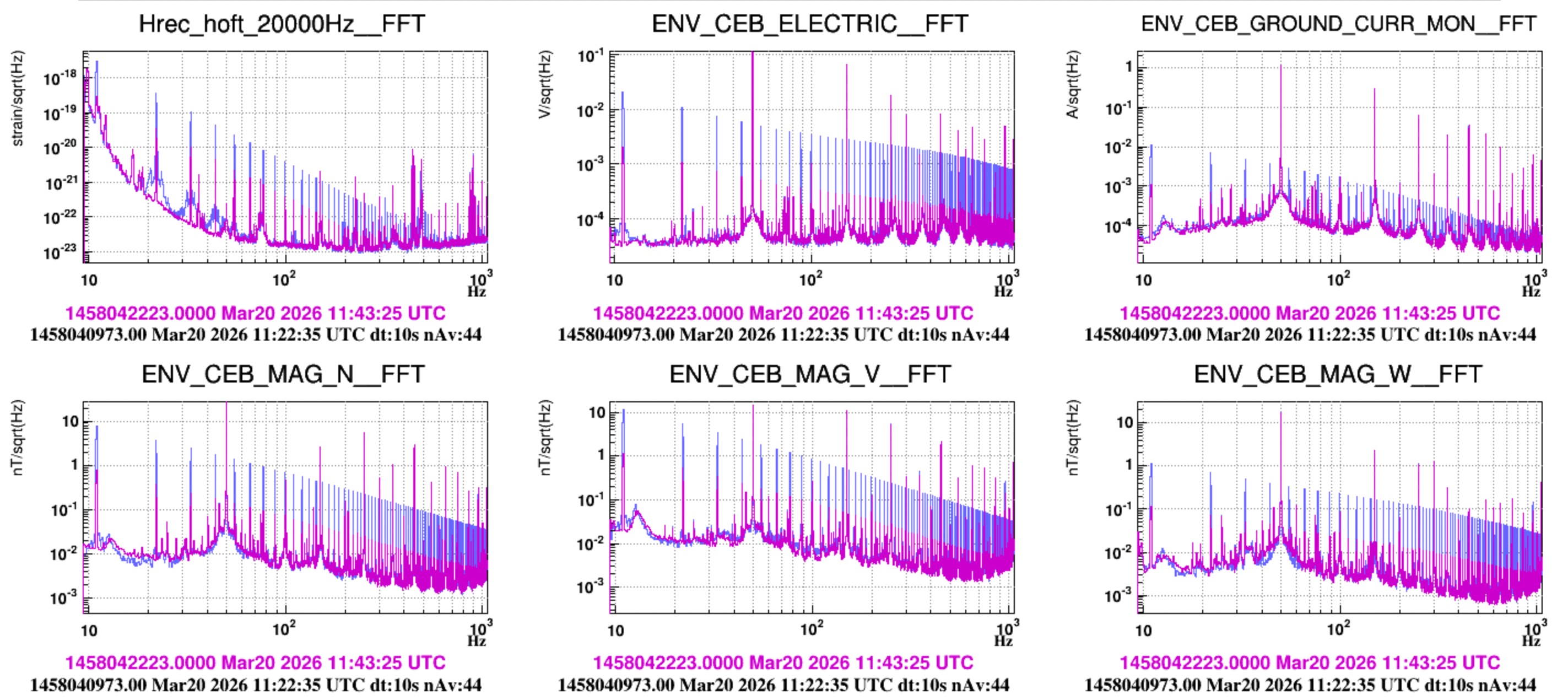
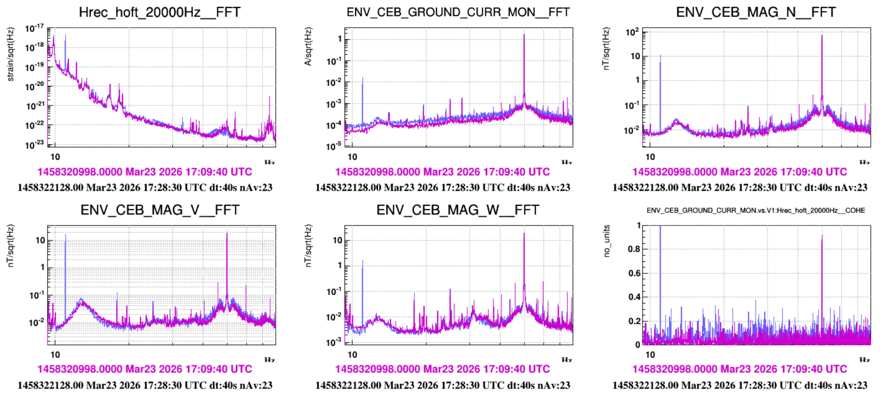
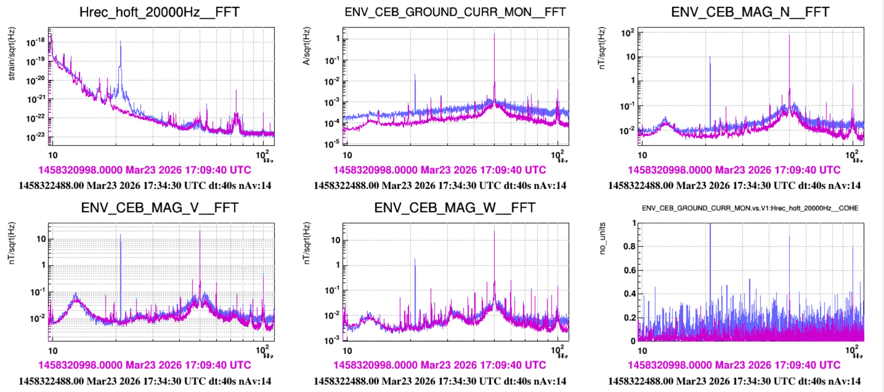
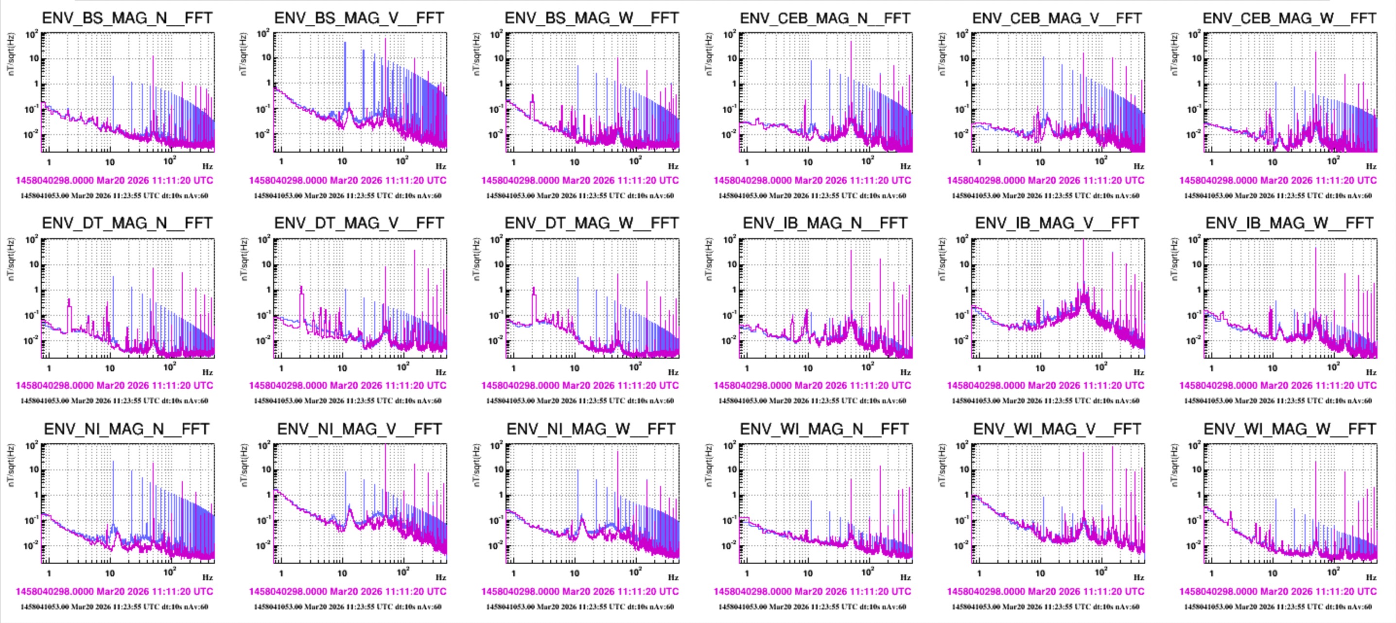
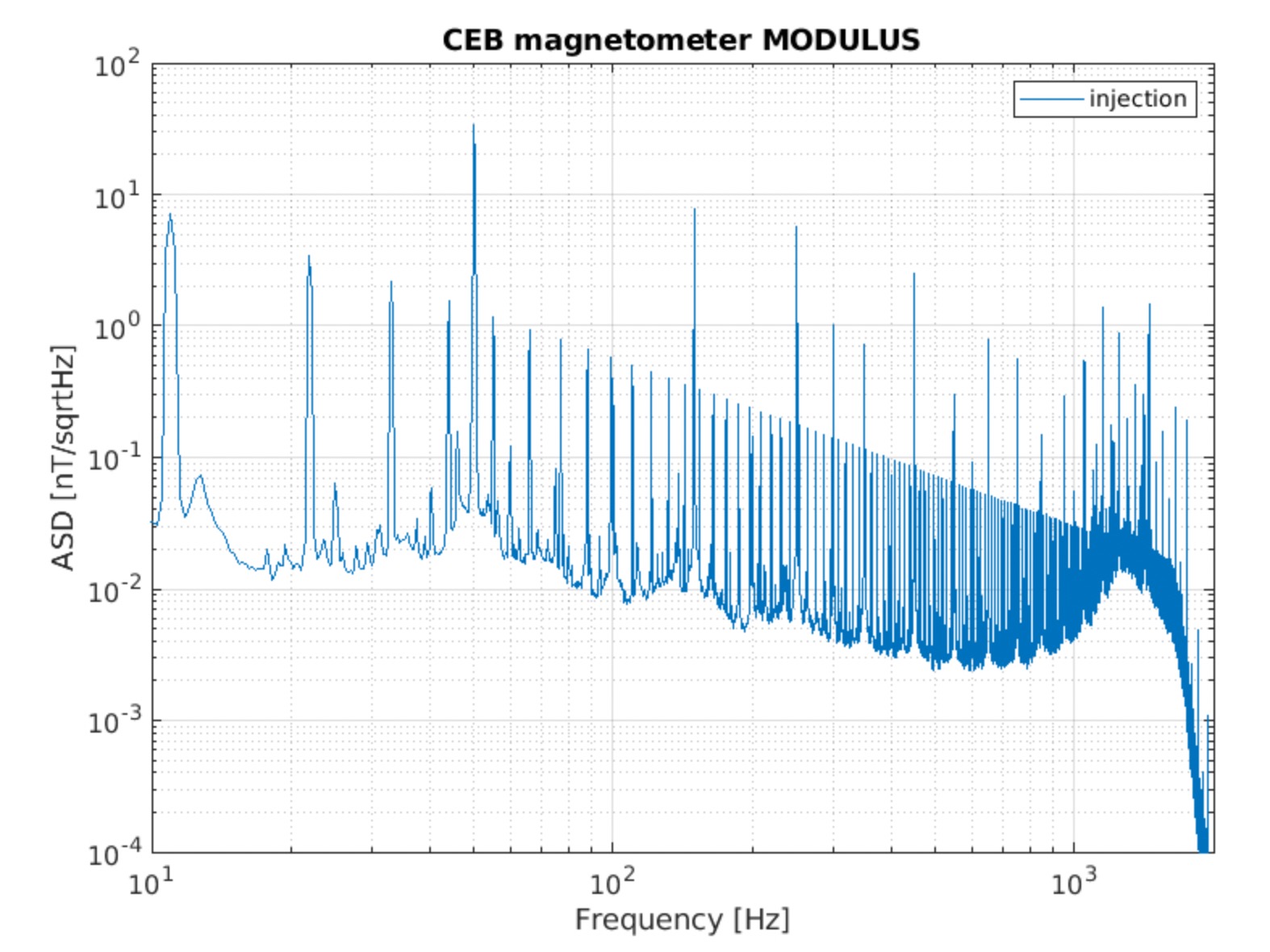
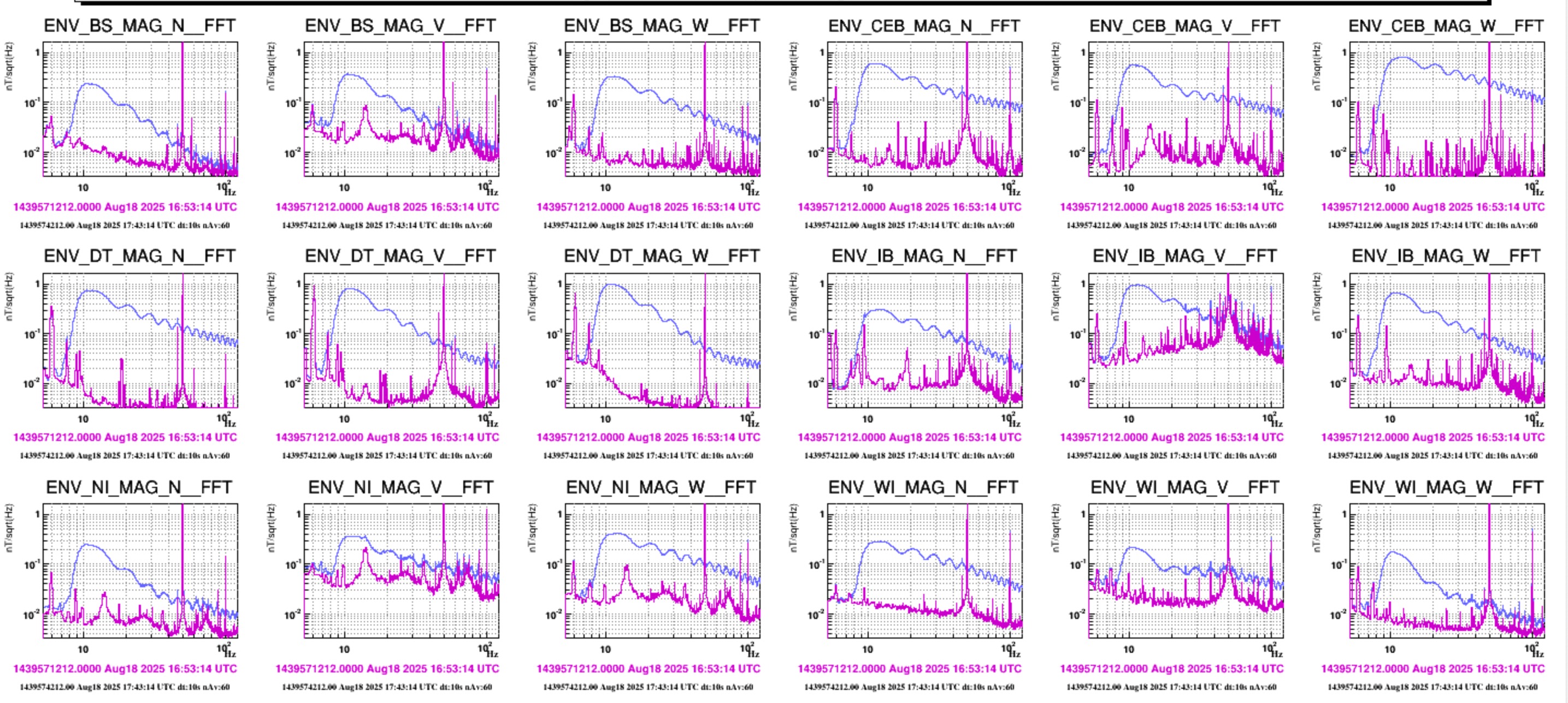
The comb is sensed widespread: by the current clamp (above) and by the ENV_CEB_ELECTRIC probe which is measuring the voltage difference between the WI SAT rack and the WI vacuum chamber.

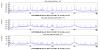
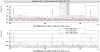
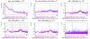
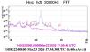
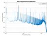
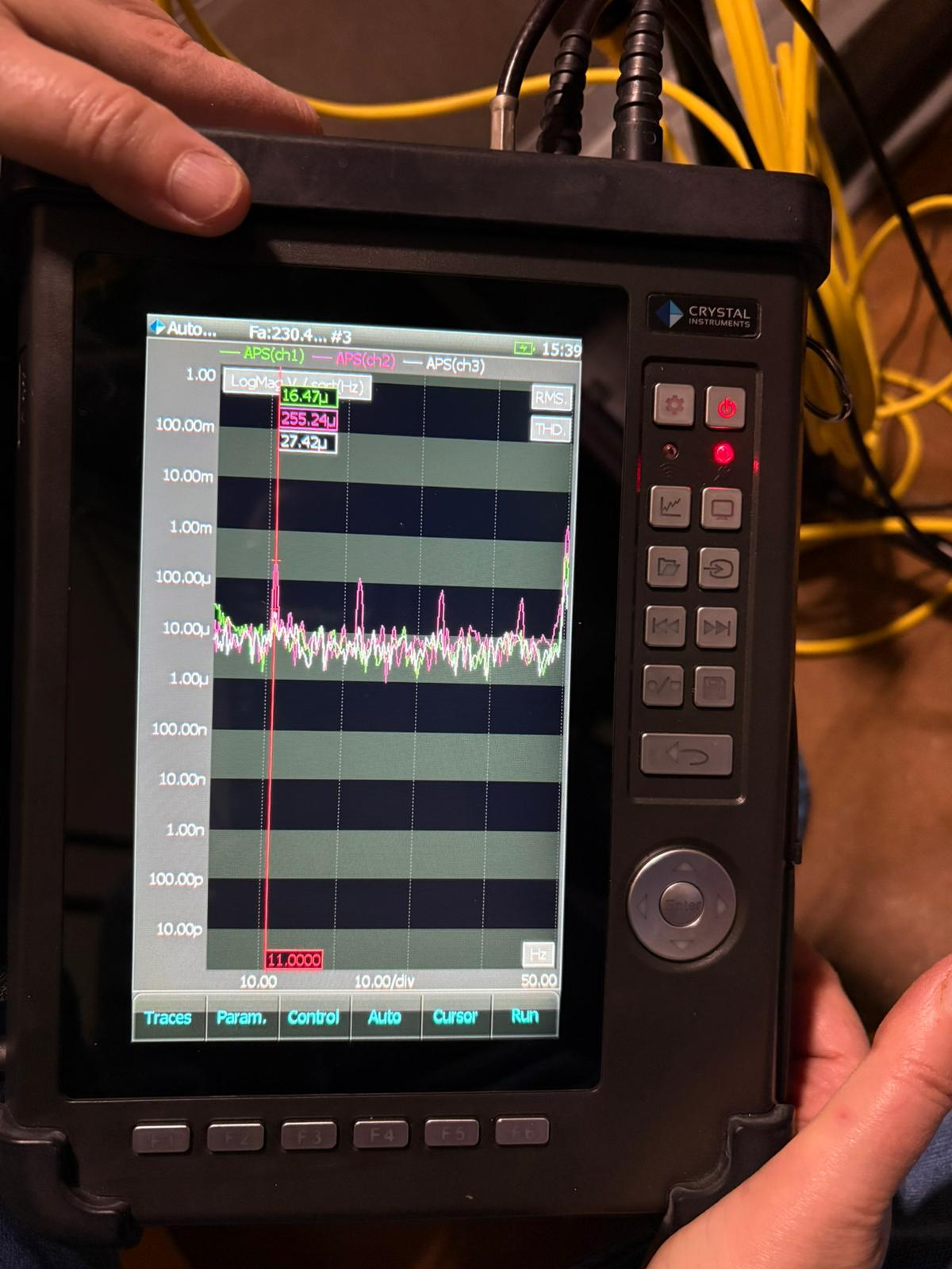
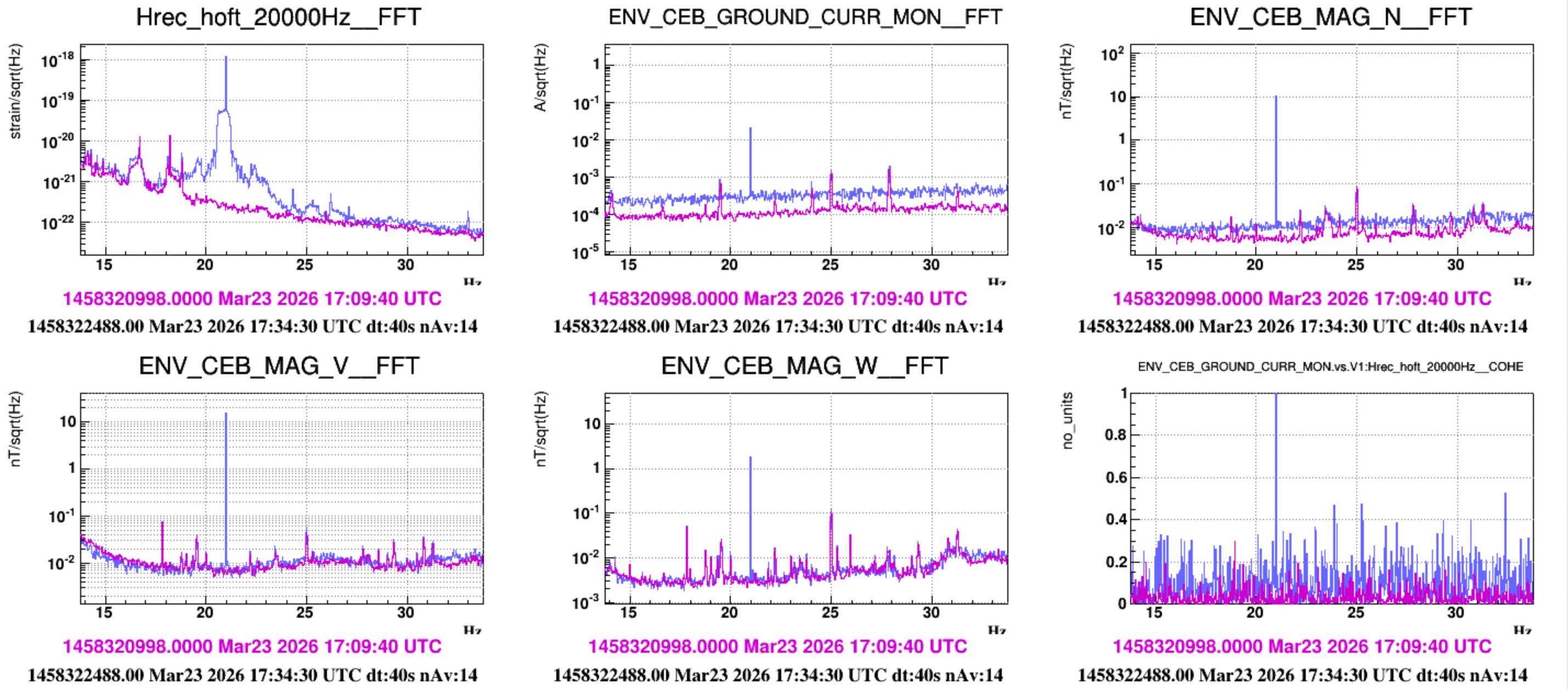
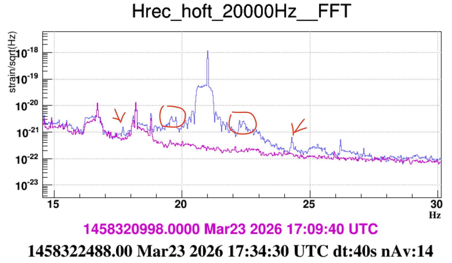
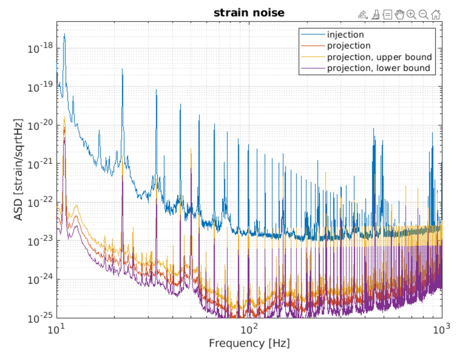
Figure 8 shows the injection (purple). In the blue curve the current clamp was disconnected from the grounding cable.


Images attached to this report
Comments to this report:
Paoletti - 18:09 Monday 16 March 2026 (68886) Print this report

During the test injection, the sensor with the best Signal to Noise Ratio is ENV_CEB_ELECTRIC, followed by ENV_CEB_GROUND_CURR_MON and ENV_CEB_GROUND_MAG.

The magnetometers near the towers all detect the Comb signal, in some cases up to three orders of magnitude above the noise floor.

This is expected: the cable running from the TIRA BAA-120W power amplifier output toward the NI suspension rack and, in parallel, toward the SR tower forms a large loop, which generates a significant magnetic field.

This must be considered when evaluating the effect in Hrec: coupling may arise from the magnetic field rather than from currents in the grounding connections, as the field can act directly on the mirror magnets.

When only real ground-current flow is present, this effect should be absent or strongly suppressed, since no large loop is formed.

Images attached to this comment
fiori, tringali, dattilo - 11:05 Monday 23 March 2026 (68927) Print this report

Friday we performed the injection with the ITF locked in LOW_NOISE_3_ALIGNED.

We tested three current levels:

  • 11:19 UTC: 5V, 0.5 A (readings on amplifier display)
  • 11:32 UTC: decreased amplitude by a factor 2: Amplifier's display readings 2.5V, 0.3 A  (note, the accuracy of the amplifier display is 1 digit)  
  • 11:39 UTC: reduced the amplitude of the injected signal from 1.2 V  to 0.24 V, tush reducing the amplitude of the injected signal by an additional factor 5

We kept injecting this signal until the ITF unlocked at 12:39 UTC.

The comb is well visible in hrec up to a few hundred Hertz. In addition to the current and the ddp (ELECTRIC) monitors,  the comb is also visible in all magnetometers in CEB (Fig. 2). In some places (BS, CEB, ...) the injected 11 Hz line exceedes 10 nT (Fig.3)

The comb amplitude in hrec has a steeper frequency slope than in the monitors and magnetometers, roughly 1/f^2 steeper (Fig. 2).

From a quick look the amplitude of the signal scales proportionally in hrec and all sensors (Figure 4).

In order to test if magnetometers were sensing a true magnetic field or they were fooled by a fluctuating ground

  • at 13:15 UTC, we set the BS Bartington magnetometer on battery supply disconnecting it from the mains: the comb signal did not change (Figure 5)
  • then, we read the BS magnetometer signals with a portable spectrum analyzer: the comb was there and the reading was the same as from the Virgo ADC. Again, we repeated the reading with the spectrum analyzer on the mains (Fig.6), and on batteries (Fig.7), the reading was the same.

We trust the magnetometers reading is a true magnetiec field produced in the CEB hall.


Images attached to this comment
fiori, tringali - 15:43 Thursday 09 April 2026 (68971) Print this report

On March 23 the same grounding current injection setup was used to inject sinus lines. The scope was to observe if any non linearity is produced in hrec, which the comb injection might have hidden. 

The UTC times are:

  • 11 Hz line from 17:20:00  to 17:29:00
  • 21 Hz line from 17:30:30  to 17:35:30

Both injections produce a large effect in Hrec (Figure 1). A large peak is seen in hrec at the same frequency of the line. As well, a large magnetic line is produced by the injection and observed by CEB magnetometers. This effect is somehow similar to what observed when the comb was injected (see mother elog).

Some non linear effect is also seen in Hrec. 

  • in the case of the 11 Hz line injection, a small (4 orders of magnitude smaller!) peak at 33 Hz (3rd harmonic) is also excited in Hrec (Figure 8). Some short excitation at 22 Hz  is also visible in hrec when the 11 Hz excitation onsets (Figure 3).
  • in the case of the 21 Hz line injection, the noise seen in hrec has a broad structure with sidebands, at +-1.4Hz and about +-3.3 Hz (Figure 10). Also, a 63 Hz (3rd harmonic, as well 4 orders of magnitude smaller) is excited (Figure 9).

Switching off the line at 17:35:30 caused the ITF to unlock (Figure 7).

One reason for a non linear coupling might be that the injected noise produce an oscillating electrostatic force on the charged mirror. In the past this was done by directly injecting a common mode voltage into the actuation coils (see https://logbook.virgo-gw.eu/virgo/?r=48306 and links therein) for the purpose of measuring the mirror charge. 

Note that, in case the noise in hrec is due solely to an electrostatic force on the charged mirror we would expect a sinusoideal electrostatic force at f to cause the mirror to move at both f and 2f if the mirror is charged, and only at 2f if the mirror is not charged (as described in page 15 of https://www.mdpi.com/2075-4434/8/4/82). The result we observe here is not easily interpreted as this kind of effect.

Images attached to this comment
fiori, tringali - 17:21 Friday 10 April 2026 (68980) Print this report

We estimated the hrec noise that the magnetic noise generated in the hall during the grounding injection would produce according with the coupling (CF) of ambient magnetic fields measured with big coils injections. The estimate is based on CEB magnetometers (Metronix).

Figure 1 shows the magnetic field modulus measured during the comb grounding injection (20 Mar 11:18 LT, 0.5 A). Figure 2  shows the measured Coupling Function using a fit of all O4 measurements, the colors correspond to the 95% confidence interval (the region that contains 95% of the measured points). Figure 3 compares the measured (blue) and projected noise (other colors). As guessed, predicted values are at least a factor 100 below measured ones.

Some considerations:

  • the distribution of the generated magnetic field across the hall is quite non-uniform, as shown in the magnetometers picture of elog 68927, magnetic field at the BS, NI and DT area is larger than at INJ tower respectively by a factor factor 100, 40 and 10. Instead, when the big coil is used for injections, the field distribution is uniform within a factor of 3 over the entire CEB hall: see Figure 4 depicting the CEB hall magnetometers response during the sweep injection of August 18 2025.  
  • A reason for such non uniformity could be the one indicated by Federico in his comment : elog 68886 (our grounding injection circuit forms a sizeable loop located in the area NI-SR).
  • For this reason, we think that the CF measured with O4 sweeps cannot be assumed a good representation of the hrec impact of the magnetic noise produced by our grounding injection.
  • We cannot exclude magnetic coupling based on this projection.
  • From a rough computation, if we were applying instead CF measured with the Bartington magnetometers located close to BS and NI towers (where, as from Federico's comment, the "injection circuit loop" is located, the project noise would be more or less a factor 10 larger than that shon in Figure 3. 
  • A last observation concerns the slope of the magnetic noise projection shown in Figure 3: in the 10-100 Hz range the measured and predicted slopes are the same: approx 1/f^3.
  • It might be interesting to evaluate predictions from magnetic CF measured with close field injections (small coil on towers base), for example nearby NI, BS and DT.
  • We could learn from repeating grounding injections from different locations, also reducing the circuit size (shorter wires), with the intent of reducing the injected magnetic fields.
Images attached to this comment
Search Help
×

Warning

Error

The present report has been modified outside this window. Please check for its integrity in the main page.

Refreshing this page will move this report into drafts.

×