Today we carried on another IPATSiA shift.
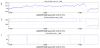
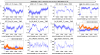
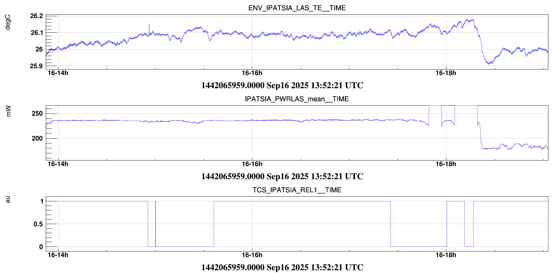
In the morning during the maintenance, we installed a new, more powerfull, chiller in order to solve the stability problem on the CO2 power we met last shifts. We ended the installation at 9:49UTC and switched ON the chiller and the laser, preparing the setup for the afternoon. With the new setup, the power is much more stable, with the temperature which remains into a variation of ~0.1⁰. Nevertheless, some small adjustments to the chiller parameters were still needed to avoid T drift which eventually caused some jumps on the power (see fig. 1).
We then started the study after reaching the LN3 state and further realigning the SR up to a DCP ~300Hz. In this way, we aimed at work in the cleanest possible state, with all the servo loop working on. Moreover, we removed the offset on SR_TX.
The CO2 power stabilized at 236mW on the pickoff (with ~47mW reaching the mirror).
At 14.35UTC we took ~20' of clean data in LN3 @300Hz DCP
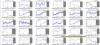
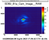
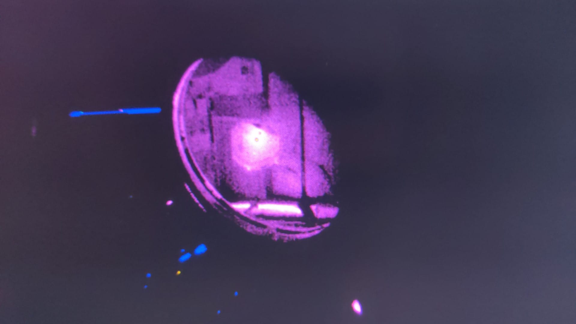
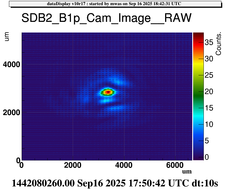
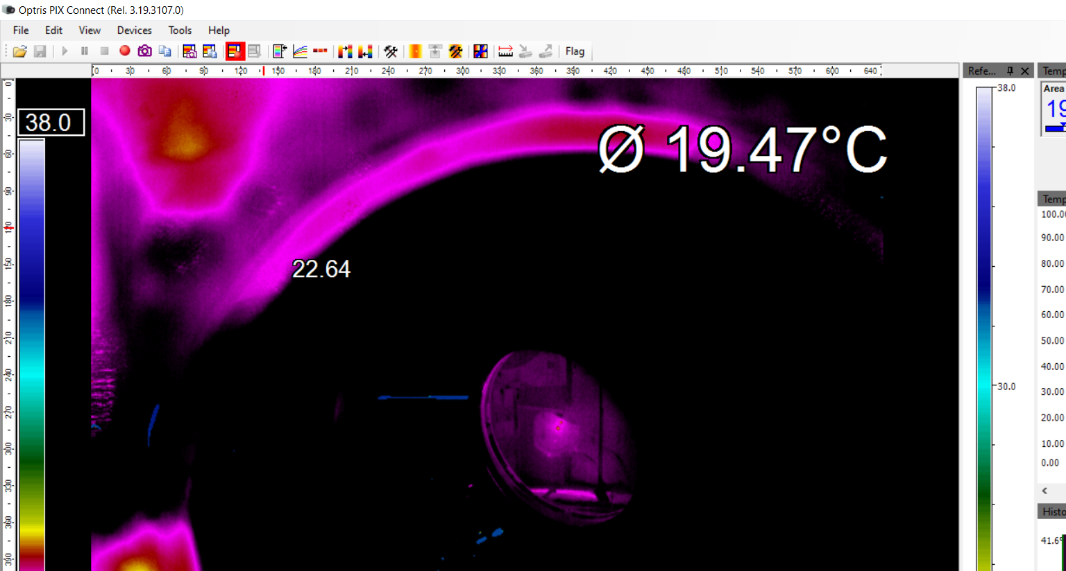
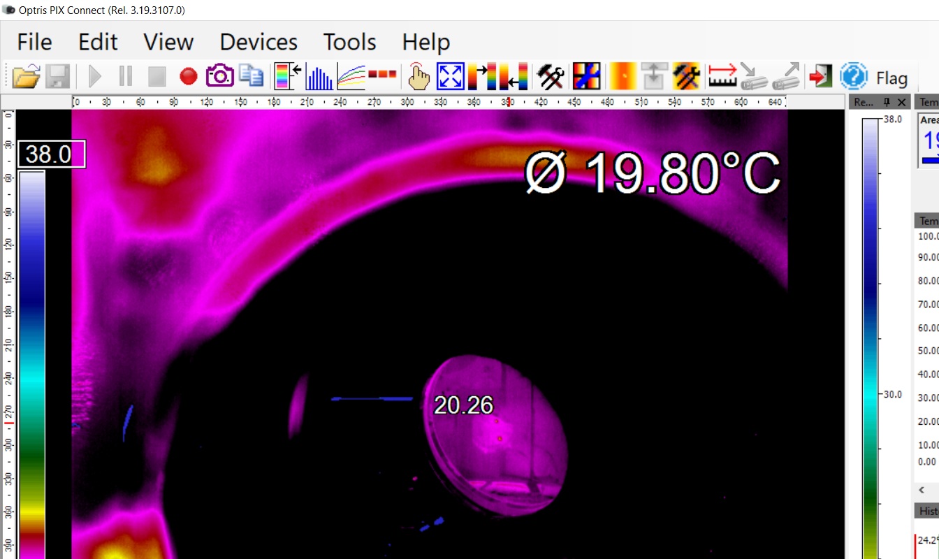
Compared to the last position of the previous shift , I came back to the central position and moved down vertically by the same amount (up on the thermocamera, see fig. 2).
At 15:00UTC we started shining the CO2-PA in the POSITION 1
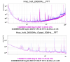
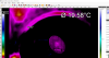
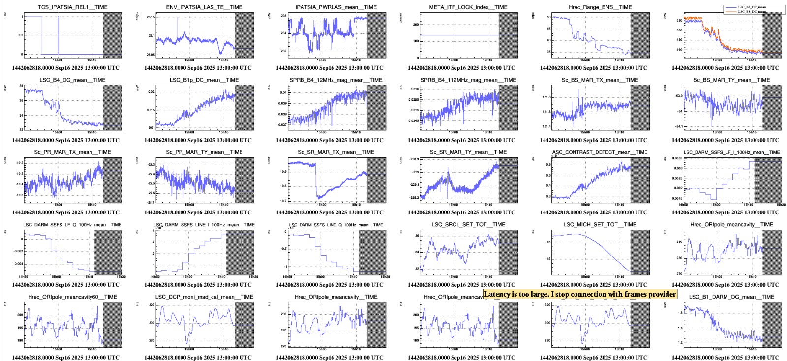
The effect on the absorpion and BNS it's this time quite huge (see fig. 3). Unfortunately, the ITF unlocked at 15:34:52UTC, probably because the BS_TY loop diverged trying to compensate for the CMRF variation due to IPATSiA (tbc).
For this reason, in the next lock we decided to disable the servo immediately before the projection of the CO2.
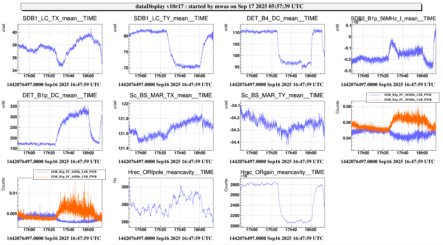
At 16:45UTC: LN3 with SR@300Hz (directly) → 15’ clean data
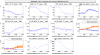
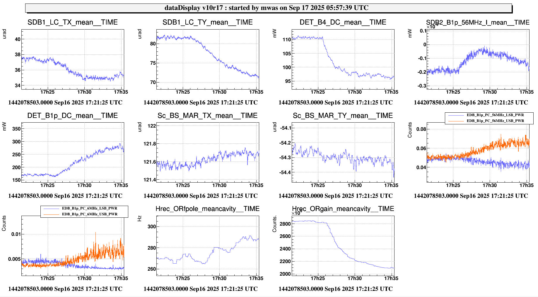
At 17:25UTC, we started shining again, in the same POSITION 1
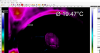
The effect of this point is clearly visible in Hrec (see fig. 4)
At 18:00UTC we stopped shining and moved to a new point, moving up (donw on the camera) from the central point, always by the same amount.
At 18:11:07UTC we started shining the CO2-PA in the POSITION 2. However, the ITF eventually unlocked few minutes later (18:16UTC).
At the next relock, I took some additional data in the same position, starting at 19:03 for 10' (this time with the BS servo ON again).
At 19.13 I blocked the laser, took the ITF in the same configuration for 10' while unmounting IPATSiA to collect other clead data (at 19.18 the new chiller has been switched OFF).
I the put back the usual setting for both DoF of the SR and the BS_TY servo.
Further analysis will follow in the next days.

