This is a quick analysis of the B5 polarization measurements with the half-wave-plate installed.
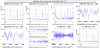
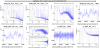
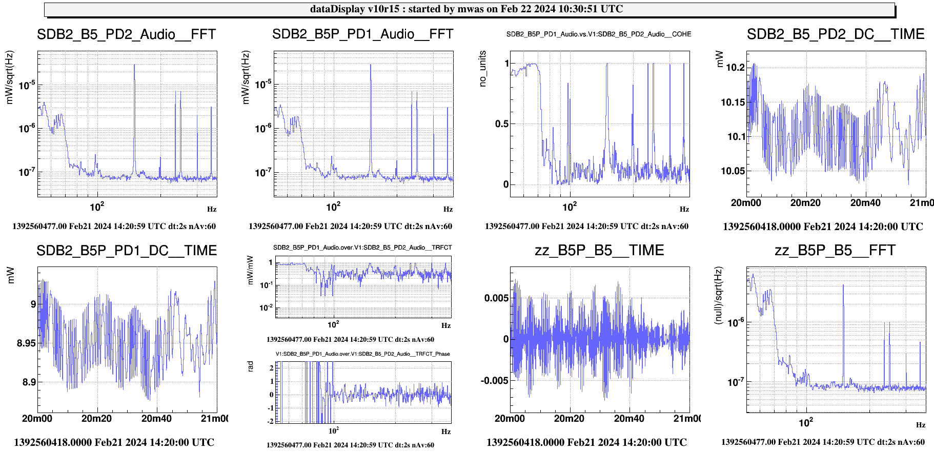
Figure 1 shows data with the B1p beam in single bounce propagating through the B5 beam path. The power on the B5 PDs was expected to be equal, this is not the case. The ratio of powers is 0.6 which is a bit unexpected. It could be due to the B5 beam path that is not in the horizontal plane and might be rotating the polarization axis of the beam. This is also not consistent with the fluctuations of power on the photodiode in the audio channel were the ratio is ~0.8. Using that 0.8 ratio to create the difference between B5P and B5 in dataDisplay. The difference spectrum has a noise floor at 8e-8mW/rtHz, and one can notice that the difference is working as the PSTAB line at ~235Hz is a factor few lower than in the individual photodiodes. This noise floor is consistent with shot noise of ~19mW (sum of the two photodiodes).
Following the equation in VIR-0032A-24 with phi=pi and alpha=pi/8. The ratio of the power difference to the power sum should be equal to twice the polarization fluctuation, hence the upper limit on the polarization fluctuation of the input beam is 8e-8mW/rtHz / 19mW / 2 = 2.1e-9 rad/rtHz. This is a factor 3 improvement over the previous measurement.
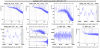
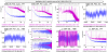
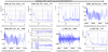
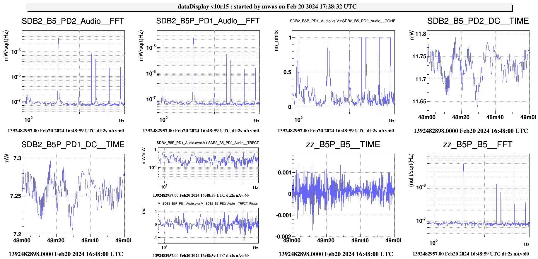
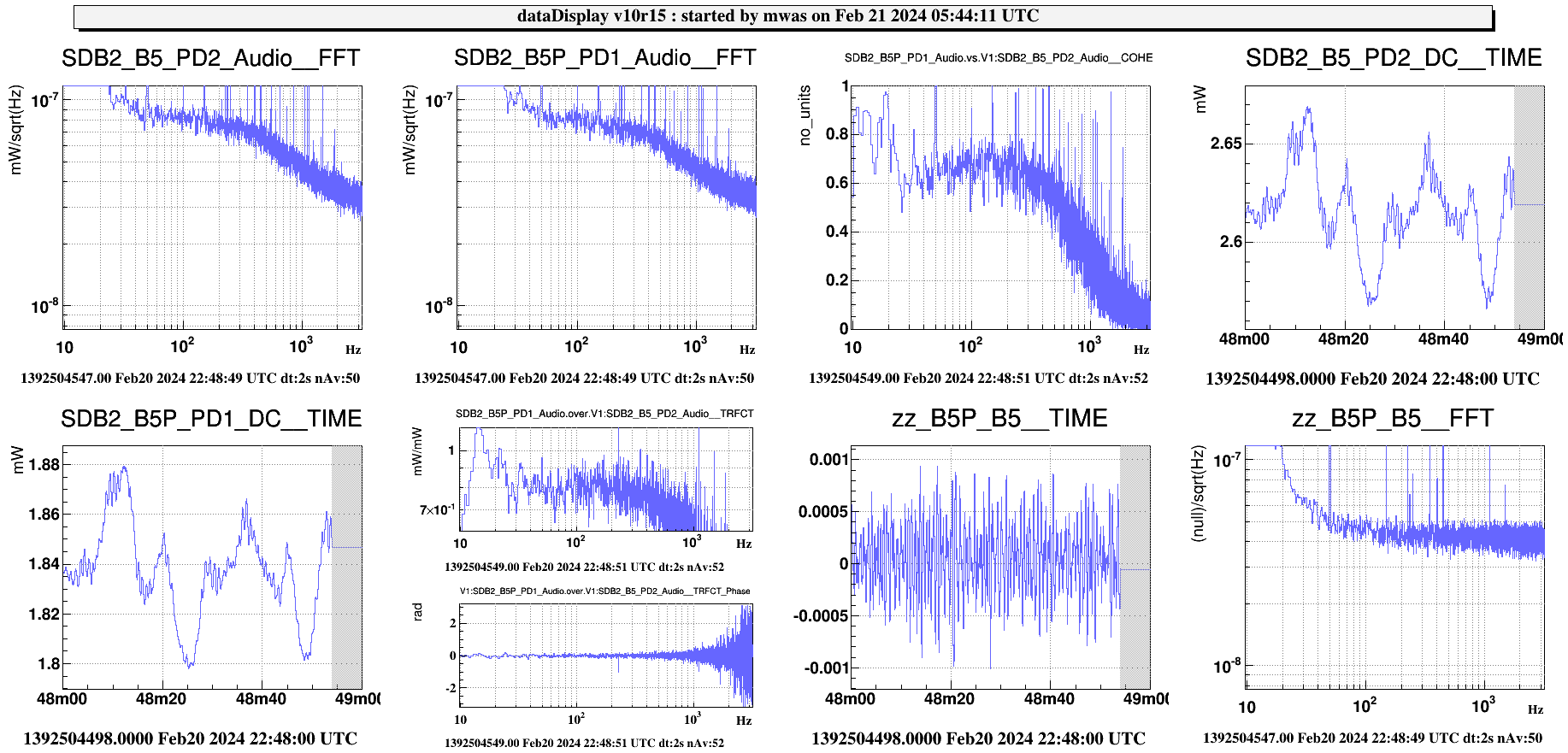
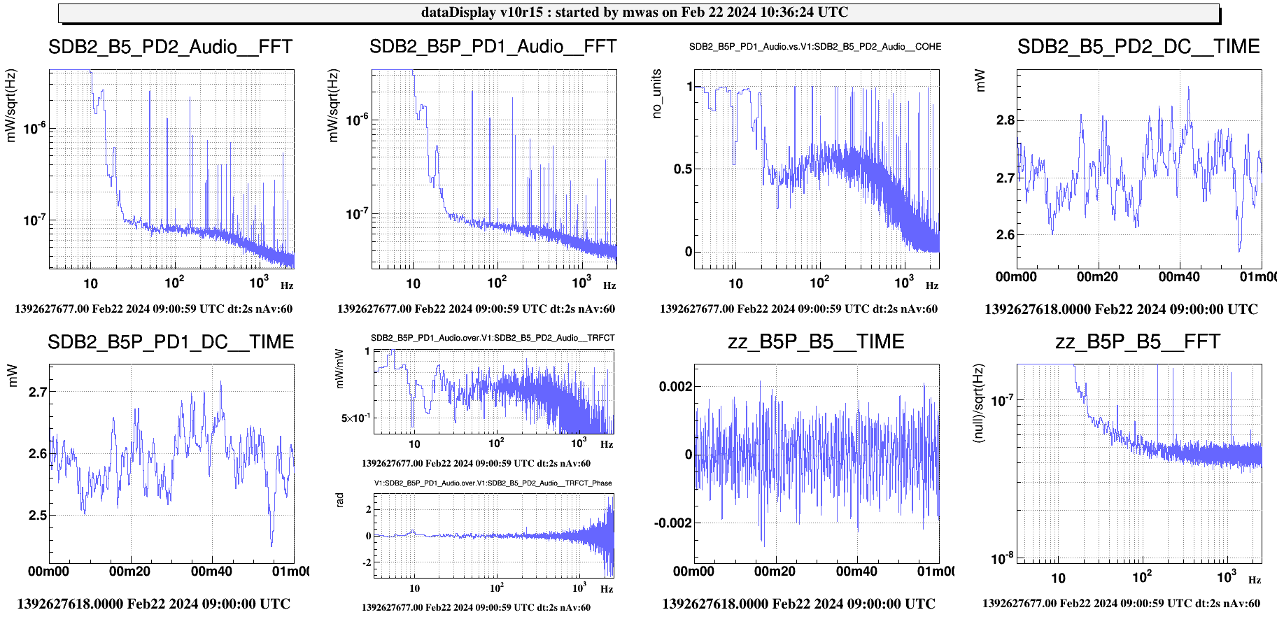
Figure 2 shows data in LN3. The B5 photodiode are limited by the excess noise that has a pole at 500Hz shape that is visible B2, B4, B5, but the same B5P - 0.8*B5 difference as in single bounce is able to remove it and the result has a noise floor of ~4.4e-8 mW/rtHz, The shot noise of the 4.5mW beam is expected to be 3.9e-8 mW/rtHz, once adding to it the photodiode electronic noise floor of ~2e-8 mW/rtHz (see figure 3) the noise floor is well explained by shot noise + PD electronic noise. The polarization fluctuations in the arms are amplified by a factor 40 by the BS AR coating polarizing reflectivity. So the upper limit on the polarization fluctuation of the beam in the north Michelson arm is 4.4e-8 mW/rtHz / 4.5mW / 2 / 40 = 1.2e-10 rad/rtHz. A factor 10 improvement over the previous upper limit. Note that this measures polarization fluctuations that are in phase with the S-polarization beam, the quarter wave plate needs to be installed to perferom the measurement of the fluctuations that are in quadrature of the S-polarized beam.