This morning we opened the SDB2 minitower to install a half waveplate on the B5 beam path for polarization noise investigations, and to replace the B1s photodiode that was showing an excess of dark noise.
The detailed procedure that we have followed is described in the attached task sheet (shift 1).
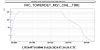
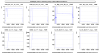
The first figure shows the overall venting and pumping cycles of the minitower. The tower venting took place from 7h40 to 8h30 utc. The pumping was started after the completion of the intervention around 13h10 utc and was stopped around 16h38 utc. The evacuation took a bit longer than usual because for the first two hours of pumping we had not opened widely the valve.
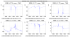
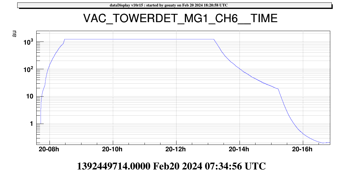
In the first part of the intervention we worked with the bench blocked at a position close to the nominal one (Figure 2) and Francesco set up the NI single bounce beam for alignment reference. In this configuration the B1p and B5 beams were reaching their corresponding photodiodes.
We installed the half waveplate on the B5 beam path and positionned it to have the beam roughly centered on it. After installing the waveplate we also installed a glass beam dump in reflection of the waveplate to dump the reflected ghost beam. The position of the ghost beam was checked with an infrared viewer borrowed to the EGO optics group.
On the B1s beam path we replaced the old B1s photodiode (air box 26) by a newly prepared photodiode (air box 12). We tested the Vbias, the shutter, and updated the DC/audio calibration factors and the current limit threshold on the SDB2 dbox bench configuration.
Below is a summary of the added/removed weight:
- Added weight: half waveplate (445 g), glass beam dump (172 g), air box 12 (871 g), several added counter-weights (481 g, 52 g) > total added = 2021 g
- Removed weight: air box 26 (858 g), several counter-weights removed (221 g, 943 g) > total removed = 2022 g
Thus the total mass of the bench remained constant within 1 g.
After adjusting the bench weight, we released the bench, added some temporary weight to adjust the height, and then balanced the bench. We could then closed the angular and position loops of SDB2 and checked that the B1s and B5 photodiodes were reasonably aligned. We also checked again the centering of the waveplate.
Finally, we adjusted the temperature of the OMC close the TEM00 resonance and we checked that there were no ghost beam visible with an infrared card in front of the B1_PD3 photodiode.
After closing the minitower we realized that the timing of the SDB2 debox bench had jumped during our intervention. We recovered it by reconfiguring the SDB2 dbox as follows:
- 2024-02-20 14h04m47 UTC Reconfigure SDB2_DBOX_LeftDown in SDB2_dbox_bench
- 2024-02-20 14h06m01 UTC Reconfigure SDB2_DBOX_LeftUp in SDB2_dbox_bench
- 2024-02-20 14h07m23 UTC Reconfigure SDB2_DBOX_RightUp in SDB2_dbox_bench
- 2024-02-20 14h08m16 UTC Reconfigure SDB2_DBOX_RightDown in SDB2_dbox_bench
Once the bench was back in vacuum we could close the bench and suspension loops at 14h18 utc. An adjustment of the bench microspring was performed later in the evening (around 19h45) by Henk Jan because the bench was getting 1.2 mm away from its nominal height (https://logbook.virgo-gw.eu/virgo/?r=63342).
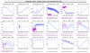
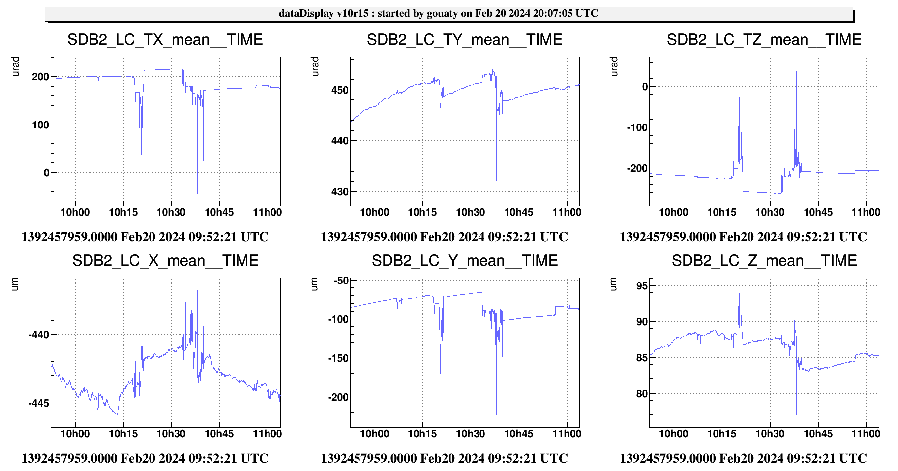
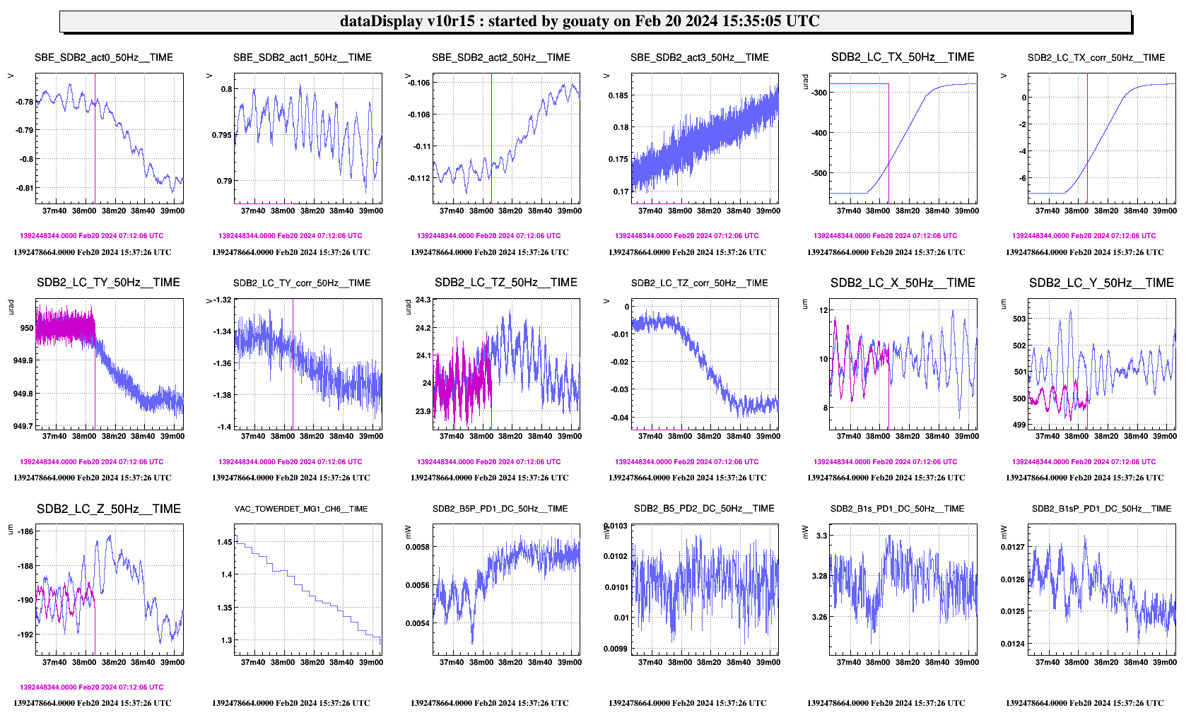
With the SDB2 bench controlled under vacuum, we checked the alignment of the B1s and B5 photodiodes. To this purpose we scanned the angular position of SDB2 in TY and TX. The centering of the B5 photodiodes was improved by performing +1100 steps with the picomotor B5_M3_H. Figure 3 show a scan of the bench in TY performed after this alignment optimization.
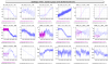
When scanning in TX, there was no effect when going to -80 urad. On the other side, we observed a slight decrease of B5P power around -450 urad (see Figure 4). since B5_PD2 power is constant, we decided not to change the alignment.
Collected 3 min of data for B1s blending starting from 15h45 utc.
Checking OMC demodulation phase: OK
Measurement of the single bounce beam polarization fluctuations with the B5 polarization analyzer:
Starting from BS nominal: TX 64 urad, TY -26 urad > Go to TX -516 urad, TY +73 urad at 16h08 utc to send the single bounce beam to the B5 photodiodes.
We adjusted SDB2 angular setpoints to maximize the power on B5: TY changed to 1450 urad and TX changed to -200 urad (although there was no effect in TX).
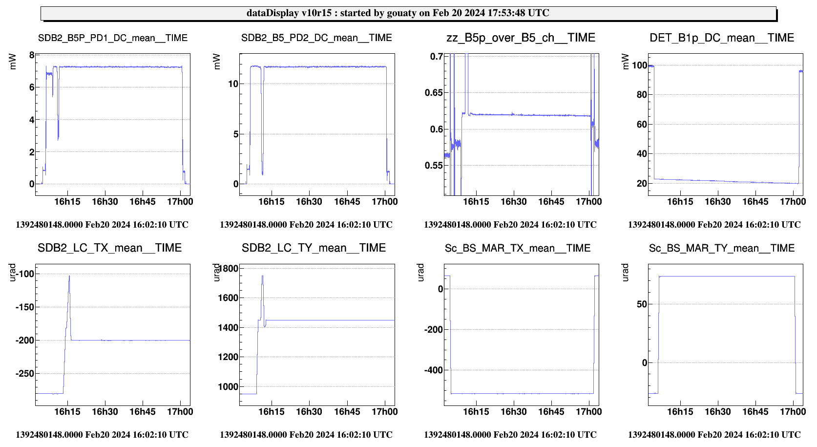
Collecting data from 16h18 utc, but the SDB2 pump is still running. We have 7.25 mW on B5P_PD1 and 11.7 mW on B5_PD2 (see Figure 5).
SDB2 pump stopped around 16h40 utc. Collecting clean data from 16h45 utc (15 min).
Restoring SDB2 nominal angular position at 17h06 utc.
Restoring B5 QD2 offsets for dark fringe at 17h19 utc
The ISC team then performed the recovery of the ITF (see dedicated entry).
Taking good data with BNS range around 51 Mpc at 21h10 utc (10 min).