This morning we opened again the SDB2 minitower to install a quarter waveplate in replacement of the half waveplate along the B5 beam path.
We proceeded following the task sheet attached in https://logbook.virgo-gw.eu/virgo/?r=63332 (shift 3).
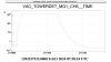
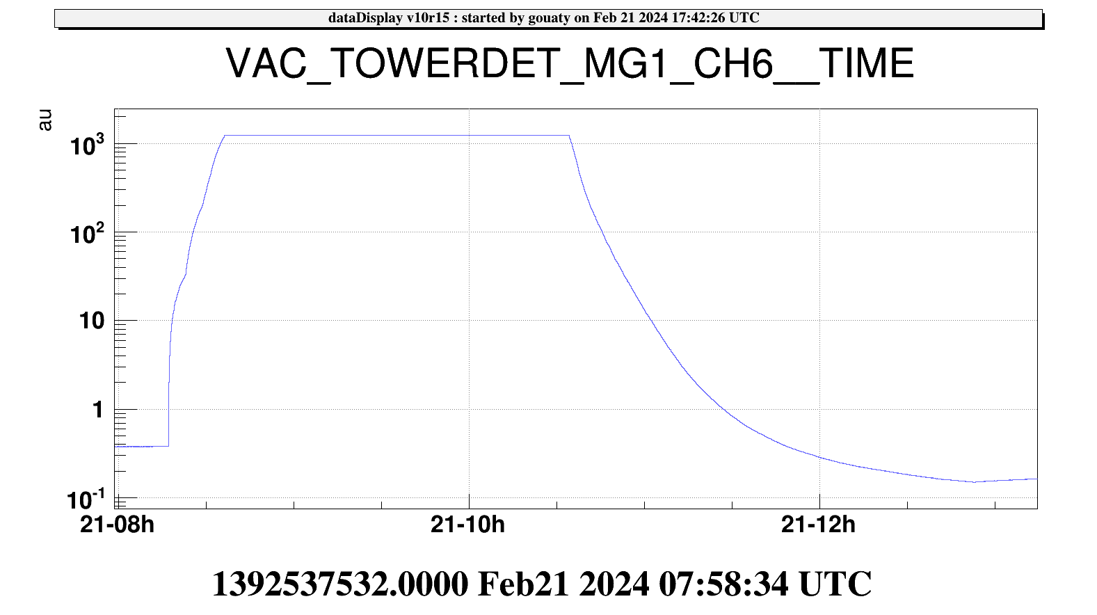
The SDB2 tower venting was started at 8h17 utc (see Figure 1) and the vacuum chamber was opened around 9h15 utc.
After opening the tower, we blocked the bench in a position close its nominal setpoints as we already did yesterday. Nicola had already put the ITF in NI single bounce.
We took a reference of the position of the half waveplate using the Thorlabs tool RSPC, then we removed the half waveplate and installed the quarter waveplate. We tried to check the position of the ghost beam in reflection of the waveplate but we did not manage to see it even with the IR viewer. However we are rather confident that we have put a tilt angle on the waveplate very close to the one put yesterday that allowed to send the ghost beam on the glass beam dump.
Checking the weight of each waveplate (half waveplate: 389 g, quarter waveplate: 373 g), there is a difference of 16g. We added a small weight on the bench to compensate exactly this difference.
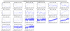
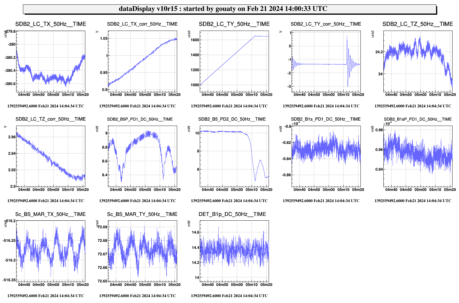
We released the bench and added some temporary weight to adjust the height. Then we could immediately close the angular and position loops of the bench (Figure 2). Activity concluded on the bench. We closed the minitower and restarted pumping at 10h34 utc. Pumping was stopped around 12h53 with a residual pressure of 0.16 mbar (Figure 1).
During the evacuation of the tower, we went to the CB platform to replace a faulty open loop picomotor driver 8742 on the SDB1 rack. The driver SN 10585 was replaced by the driver SN 10592. The problem with the old driver was that we were not able to communicate with the closed loop drivers which were chained to this open loop driver. With the new driver, we could rechained the closed loop drivers and restarted successfuly the SDB1_Pico process.
After the SDB2 intervention we reconfigured the SDB2 DAQ boxes to recover the timing:
- 2024-02-21 11h29m16 UTC gouaty Reconfigure SDB2_DBOX_LeftDown in SDB2_dbox_bench
- 2024-02-21 11h30m11 UTC gouaty Reconfigure SDB2_DBOX_LeftUp in SDB2_dbox_bench
- 2024-02-21 11h30m59 UTC gouaty Reconfigure SDB2_DBOX_RightUp in SDB2_dbox_bench
- 2024-02-21 11h31m45 UTC gouaty Reconfigure SDB2_DBOX_RightDown in SDB2_dbox_bench
After the recovery of the SDB2 vacuum we noticed that the SDB2 X position was off by about 950 um, which prevented to close the position loops. Alessandro Bertolini was called and he restored the nominal working point of the bench.
With the interferometer in NI single bounce we made a first attempt to measure the polarization fluctuations by sending the single bounce beam to the B5 beam path:
To this purpose we changed the BS angular position to the following setpoints: BS_MAR_TX = -516 urad, BS_MAR_TY = +73 urad. Since we forgot to open the B5 beam drift control during the BS misalignment the corrections went to saturation. We opened and closed the angular loops of SDB1 and put the fixed setpoints.
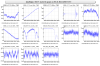
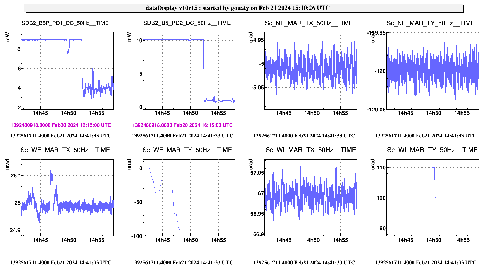
Adjusting SDB2 angular position to align the B5 photodiodes. Starting from TY= 950 urad TX = -280 urad. We set TY at 1450 urad which seems to correspond to an optimum for the B5P photodiode (see Figure 3) and TX at -360 urad.
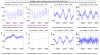
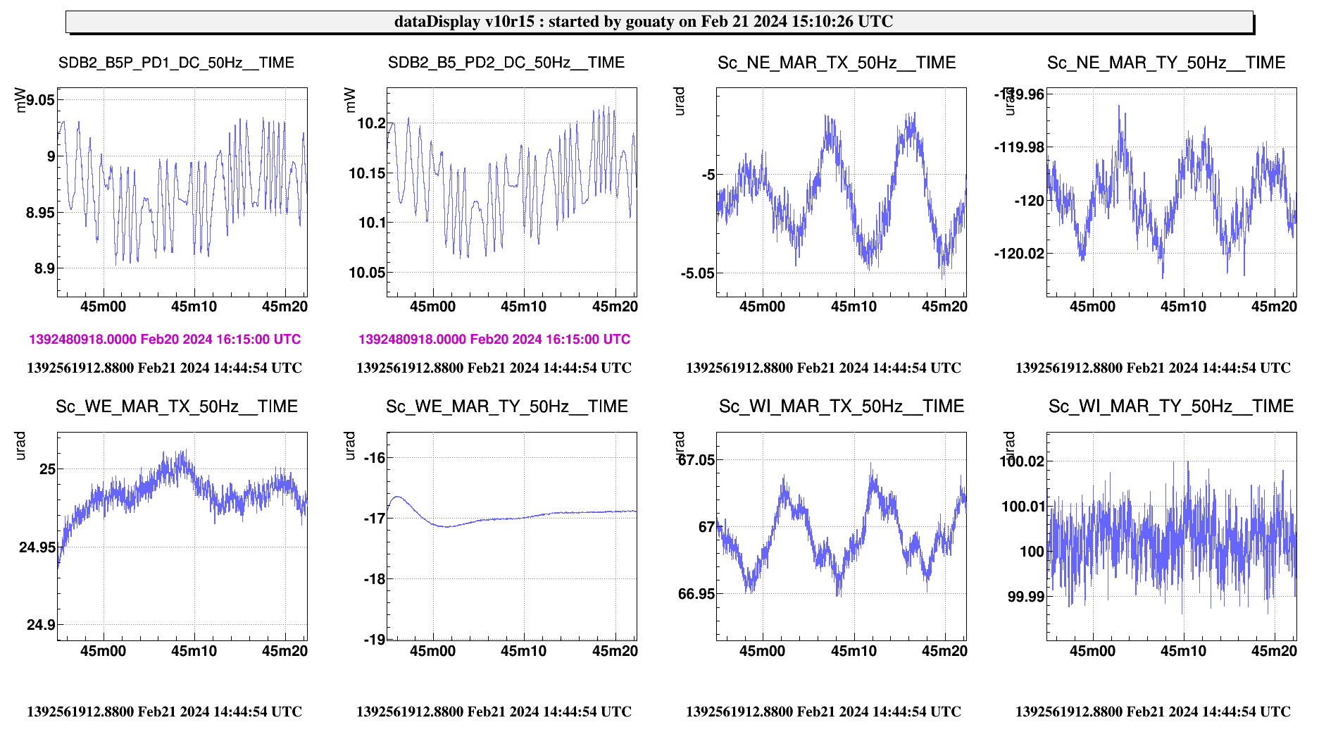
Collecting quiet data from 14h18 utc to 14h29 utc. The power distribution is now better balanced between the B5P (~9 mW) and the B5 (~10.15 mW) photodiodes. Noticing fluctuations on the photodiodes (Figure 4) we checked the impact of changing the alignment of the mirrors. And we found that the WI misalignment was moving the beam on the photodiode (Figure 5). Thus we were not on the NI single bounce but rather on the WI single bounce.
At this point we were confused about the general alignment of the ITF so we relocked the arms to restore the standard alignment conditions, then misaligned again the BS to try again the polarization noise measurement.
It turned out that we were still on the WI single bounce (this may have been already the case yesterday). We took anyway 5 min of data in this configuration, starting from 16h19 utc (6 min), but similar fluctuations on the B5 photodiodes we still present.
From this point we started the recovery of the ITF lock, see dedicated entry.
B1s blending was measured using data collected in single bounce yesterday (https://logbook.virgo-gw.eu/virgo/?r=63332) and the blending filter was updated at 17h11 utc. The quality of the new blending remains to be checked.