Reports 1-1 of 1 Clear search Modify search
AdV-DET (Commissioning)
capocasa, bersanetti, hui, mwas, gouaty, casanueva, magazzu, mantovani, ruggi, spinicelli, barsuglia, derossi - 23:44 Tuesday 30 August 2022 (56891) Print this report
OMC lock in dark fringe and DARM hand-off to DC readout

This afternoon, we locked the OMC at dark fringe and performed the hand off of DARM to DC readout.

ITF locked in CARM null at the beginning of the shift.

DARM offset set to -0.2.

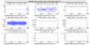
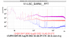
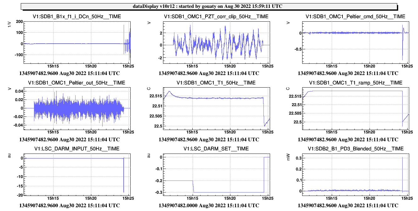
OMC locked on B1_PD3 at 15h12 utc. DARM_SET increased to -0.3. ITF unlocked when trying to perform the hand-off of DARM to DC readout at 15h24 utc. (Fig.1)

ITF relocked in CARM null.

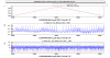
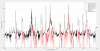
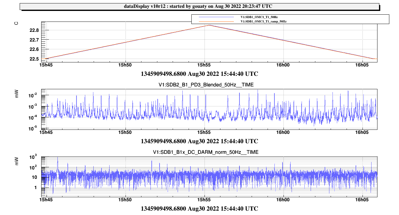
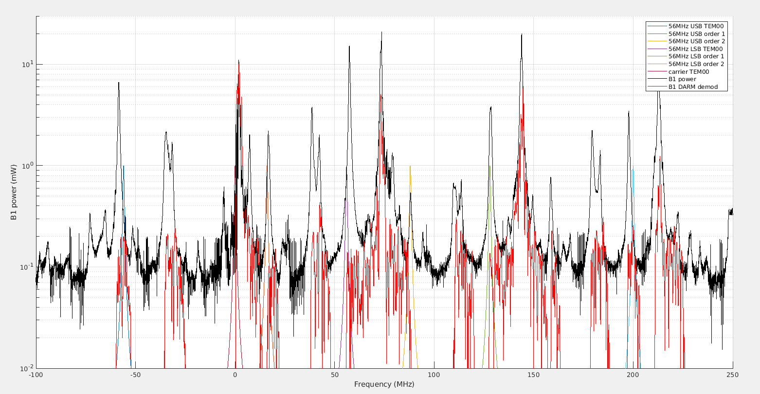
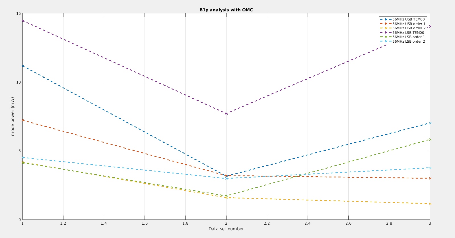
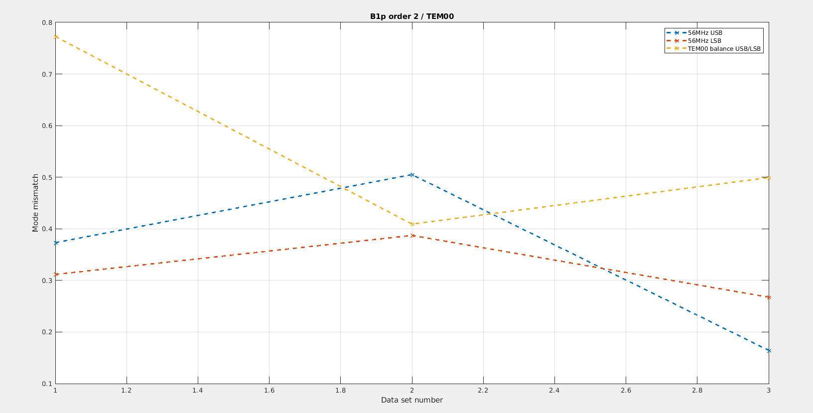
OMC scan started at 15h44m50 utc for optical characterization, ended at 16h05m40 utc (Fig.2)

DARM_SET to -0.5

Trying to lock OMC with OMC_LOCK: attempt failed. The node returned the following error message:

2022-08-30-16h11m07-UTC>WARNING-[ACQUIRE_OMC1.main] USERMSG 0: EZCA CONNECTION ERROR: Could not get value from channel: SDB2_B1_PD3_VBias

We tried to reload the OMC_LOCK node, but it got stuck. We put it in PAUSE.

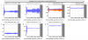
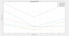
We then locked the OMC with VPM at 16h23m30 utc (Fig.3)

DARM offset increased to -0.75

Hand-off DARM to DC readout with B1_PD3 at 16h35m50 utc

Check that B1 PD1+PD2 audio is not saturating. Audio below 0.1 mW (saturation should be at 0.4 mW)

Hand-off of DARM to B1 PD1+PD2 at 16h44m20 utc

Tuned B1 PD2 demodulation phase. Config file updated at 17h01m53 UTC

Tuned gain of error signal B1_f1_i_DCn_err. Config file updated at 17h32m48-UTC.

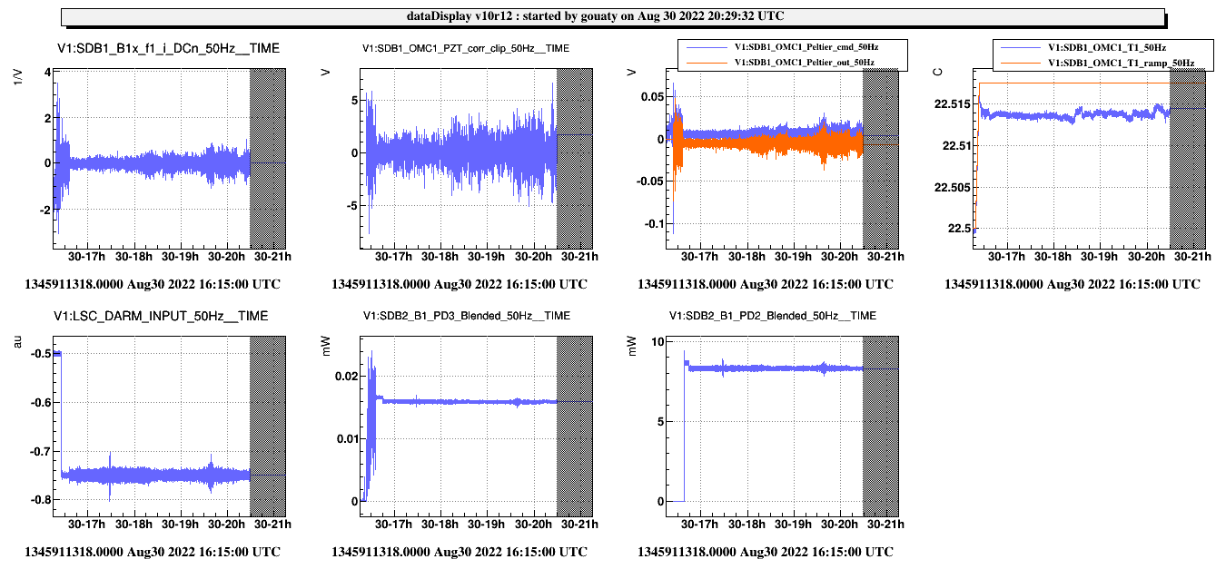
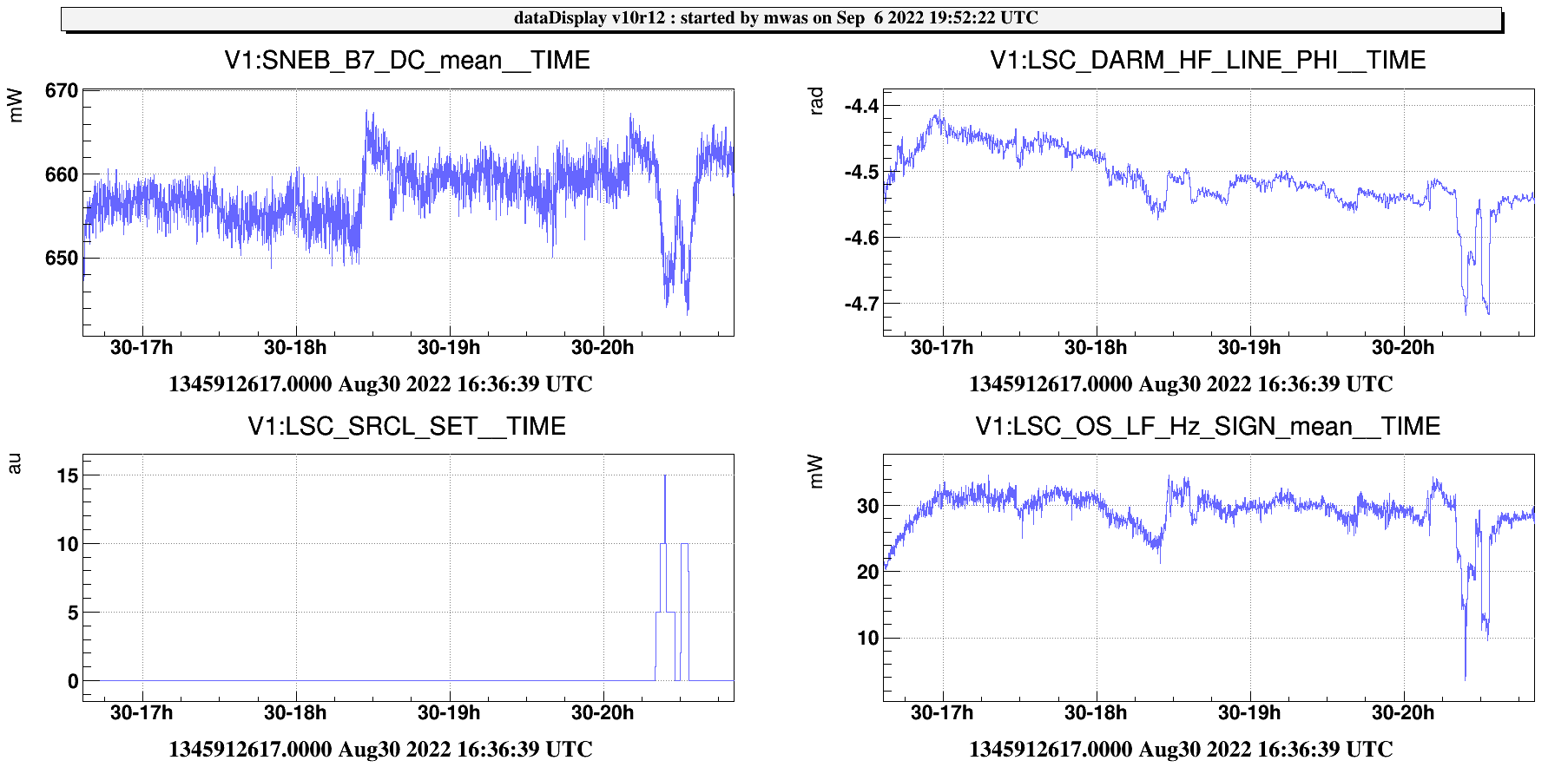
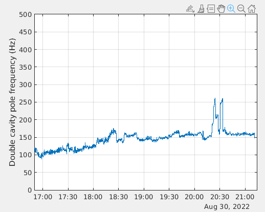
Leaving the ITF locked in DC readout for the rest of the shift (until ~21h utc) to allow ISC noise injections – Fig.3

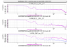
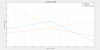
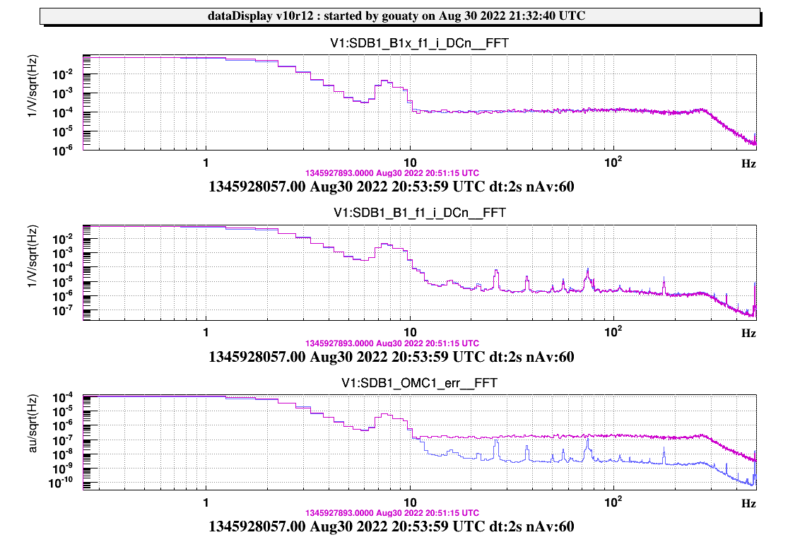
Performed OMC lock hand-off to B1_PD2 at 20h52m07 utc. Go back to B1_PD3 at 21h07m59 utc. Fig.4 shows the spectrum of the OMC error signal before (purple) and after (blue) the hand-off. Note that this hand-off was almost transparent for the ITF lock.

ITF manually unlocked by unlocking the OMC at 21h11m08-UTC.

OMC shutter closed and OMC_LOCK node put in TEMP_CONTROLLED state.

Images attached to this report
Comments to this report:
capocasa, bersanetti - 0:20 Wednesday 31 August 2022 (56893) Print this report

Pic.1 shows DARM spectrum in the 2 different cofiguration (B1p, B1_PD3, B1_DC).

We performed the following noise injection (at least 1 min of clean data each).

DOF FILTER  Amplitude  starting time (UTC)
DARM  DARM_noise 1 17.07
PRCL PRCL_noise 50 17.25
SRCL LSC_noise_MICHband 1e-2 17.33 
MICH LSC_noise_MICHband 1e-2 17.13
DARM HH DARM_noise_HH 3e4 17.50

We left DARM HH noise on almost all the time to allow measuring the DCP in different configurations.

We did a scan of the SR angular position (see pic 2). From a preliminary analysis of the DCP it seems that it is always below 100 Hz, but we want to confirm the goodness of the fit.

Optical spring was ~ 30 Hz. Around the end of the lock we tried to add a SRCL SET to decrease it and check a possible effect on DCP (HF frequency injected at that time). Data to be analyzed.

The fringe on B1p_DC was almost always higher than 0.05. Around 18 UTC it started to rise up to 1.1 (correspondingly to a decrease of OS). It was possible to reduce it by acting on SR alignment.

Unlike the lock of yesterday the BS AA was behaving correctly all the time. We uncomment its automatic engagement at carm null.


Images attached to this comment
bersanetti - 0:50 Wednesday 31 August 2022 (56894) Print this report

Concurrently with the BS drift control, also the WI F7 vertical damper has been added to the Automation; it is engaged in the CARM_NULL_1F state and disengaged in DOWN.

mwas - 10:51 Wednesday 31 August 2022 (56897) Print this report

Figure 1 shows the OMC scan in CARM null. The sidebands are much worse that what was seen 6 months ago. The reanalysis of Feb 18 data is shown on Figure 2, the scan was done less linearly at the time, so it is harder to scale time into MHz, one would need a quadratic fit to do it properly, but the linear fit should be good enough.

Mode Aug 30 (mW) Feb 18 (mW)
USB 6MHz TEM00 0.2 0.5
LSB 6MHz TEM00 0.9 2.0
USB 56MHz TEM00 3.2 7.0
LSB 56MHz TEM00 7.7 14
USB 56MHz order 1 3.2 3.0
LSB 56MHz order 1 1.7 5.8
USB 56MHz order 2 1.6 1.2
LSB 56MHz order 2 3.0 3.8


So the sideband TEM00 are about a factor 2 smaller than 6 months ago, the very large imbalance is still roughly the same. The order 2 56MHz powers are roughly the same, which means the beam mode match is worse now by a factor 2 than 6 months ago. The theoretical expectation is 110mW of TEM00 per 56Mhz sideband and 2mW of TEM00 per 6MHz sideband.

Figure 3 and 4 shows three configuration that should be comparable, CITF with SR RH at 9.8W and CHRoCC at 0.43V, CARM null with SR RH at 9.8W and CHRoCC at 0.41V (lower correction as hot POP creates same of the same effect), CARM null in February.

The 56MHz TEM00 power now in CARM null (data point 2), is a factor 2 lower than the other two cases. The mode match is a bit worse than in CITF, and much worse than 6 months ago. The LSB/USB TEM00 balancing degrades when going from CITF to CARM null, but is comparable to what it was at CARM null 6 months ago.


Images attached to this comment
mwas - 22:02 Tuesday 06 September 2022 (56950) Print this report

Figure 1 shows the impact of the SRCL SET adjustments on the optical spring, which are very clear. Eleonora told me that SRCL SET is approximately in nm. It has also a clear impact on LSC_DARM_HF_LINE_PHI, which is the phase that in principle can be converted into a double cavity pole frequency estimation.

Figure 2 shows the conversion of that phase into DCP frequency in Hz (based on an offline crude estimation). There is a clear positive impact with the pole moving from 150Hz to 250Hz. This should be confirmed by studying more closely the noise injection that were done at that time. Note that at that time DARM was in DC read-out, while the calibration of the DCP offline computation was done using RF data. And the the shift from this afternoon hints at the phase changing for different read-out, likely due to the different DAQ delays for different photodiodes and RF vs DC channels. So the calibration of this pole is likely wrong, but the conclusion that SR offset can change significantly the DCP and make it better should remain true.

Images attached to this comment
Search Help
×

Warning

×