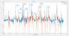
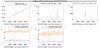
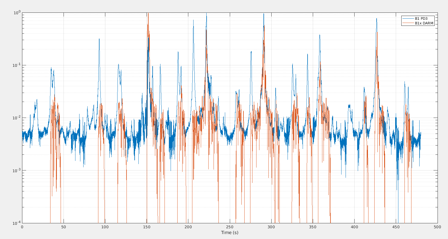
Figure 1 and 2 show the same part of the upgoing OMC temperature scan. In blue is the transmitted power, and in red is the transmitted power demodulated at the DARM length dithering frequency (73Hz?), both are normalized to 1 at the max transmission in the scan. Fig 1 is with time on the axis, and Fig 2 is the same data with time roughly calibrated into frequency compared to the carrier TEM00.
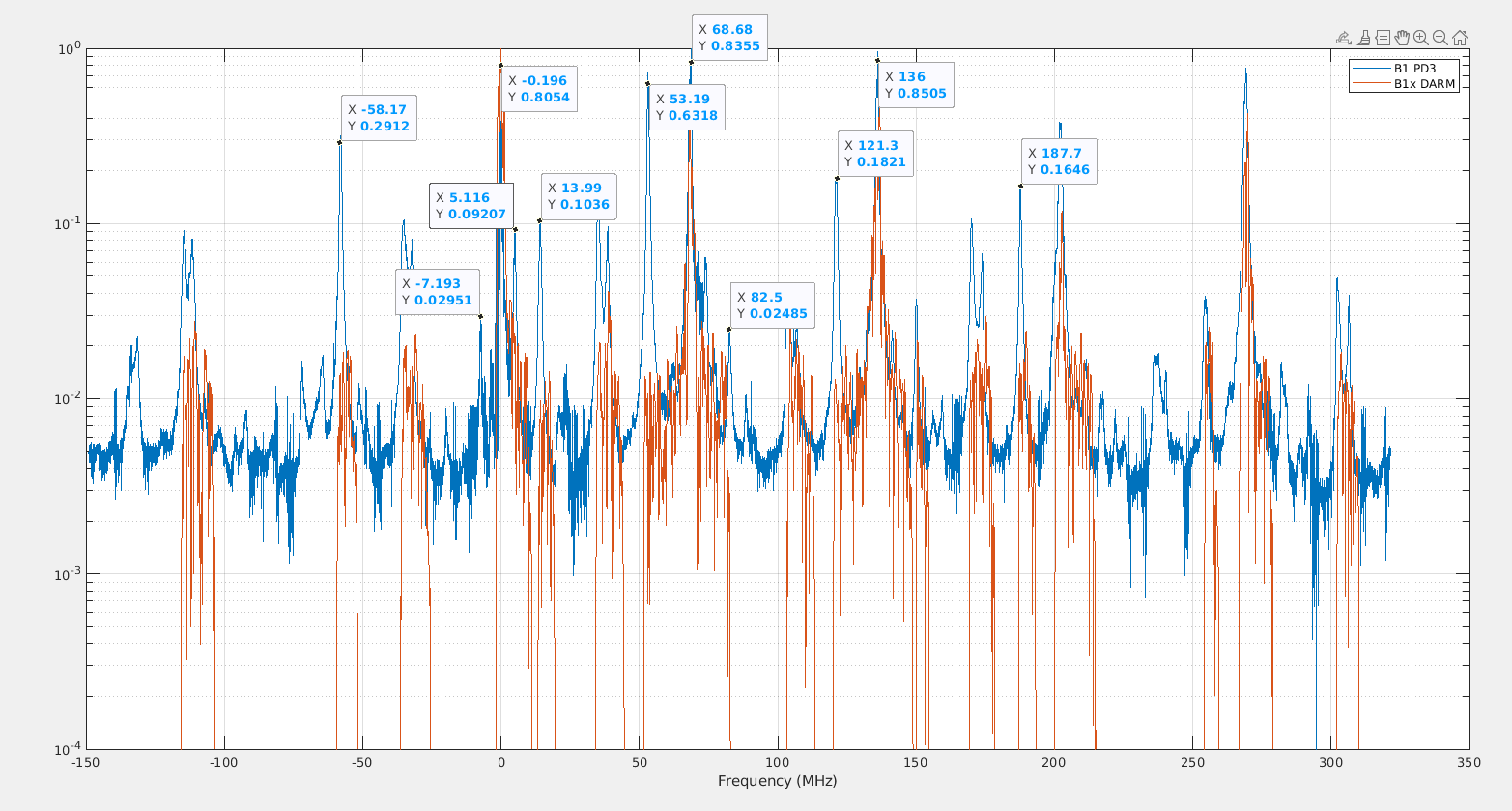
One can notice that the lower sideband TEM00 of 56MHz has half the power othe upper TEM00. And the lower 6MHz TEM00 has 1/4 of the power of the upper 6MHz TEM00. So there is a clear unbalance in the sidebands, and it is in the same direction for both sidebands. This unbalance is clearly visible in the B1p phase camera (but the convention between LSB and USB is reversed). With also a factor 2 for the 56MHz sidebands, and between a factor 4 for the 6MHz. So the OMC scan agrees with the relative sideband powers measured with the phase camera, and also with the power of the 56MHz relative to the power of the 6MHz.
Looking at the not normalized powers, there is 2mW in 6MHz USB, 0.5mW in 6MHz LSB. While from simple simulations (VIR-1225B-19) 10mW in total for LSB+USB was expected for 40W input power, and a high modulation index of 0.25. While for the 56MHz there is 6mW in the LSB, 12mW in the USB, so 18mW in total. While 600mW is expected in theory (for a modulation index of 0.25 that is likely much higher than what is actually used). Note that this is an underestimate as these side-bands are clearly not perfectly mode matched with the OMC, so the actual powers can be easily a factor 2 higher. But for the 56MHz the power seems at least a factor few smaller than expected for a perfect interferometer.
The modes (TEM00, order 1, order 2, etc) are separated by about 68MHz.
- So the LSB 56MHz order 1 mode is at ~12MHz, and USB 56MHz order 1 mode is at 124MHz. Both of them are roughly 1/3 of the corresponding TEM00 power.
- The LSB 56MHz order 2 mode is at ~80MHz and the USB 56MHz order 2 mode is at ~192MHz. The LSB has 8.5% of the TEM00 power in the order 2 mode, while the USB has 26% of the TEM00 power in the order 2 mode. It is surprising that the LSB has 2 times less power even though it seems much better mode matched with the OMC (which had been measured to have a mode mis-match to the input beam of ~3%).
Unfortunately the B1 camera image is stored in the raw data at 0.1Hz (although it is available online at ~1Hz). So the numerology above cannot be checked in images. Would it be possible to store the B1 camera image in the raw full data at the same rate as available online?
