I have looked at the double pole cavity monitors.
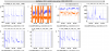
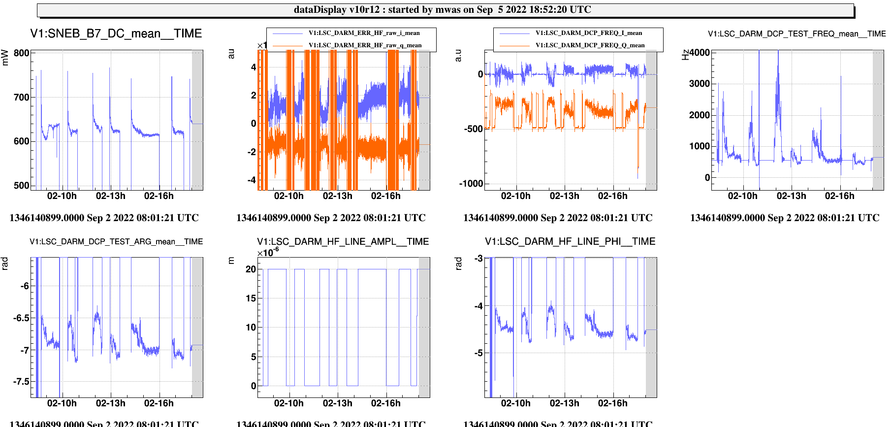
Figure 1 shows some of the double cavity pole monitor channels. There are two code, a base version, and a testin version. I am not going to look closely at the base version. The test version is clearly misbehaving giving poles at a few kHz.
Looking at the code, the issues is it is using the phase offset calibration for a line at 314.3Hz, while the line is now at 491.3Hz. The theoretical formula doesn't have the phase offset depending on the line frequency, but in practice it does because the loop phase delay due to time delay depends on the frequency we look at.
By doing a simple a transformation of LSC_DARM_HF_LINE_PHI: 491.3./tan(line_phi+5.8) one can get a reasonably calibrated signal.
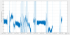
Figure 2 shows the trend since september 1. transient state with DCP at ~260Hz on Sep 1. At some times the pole because very low or even negative. My expectation is that we use here a model of single pole, while the response of the interferometer has two resonant poles when the cavity is detuned. So using the wrong model give silly results for large SR detuning. It has still the right relation, the higher the computed frequency the better.
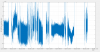
Figure 3 shows the magnitude of the 491.3Hz line on the same time scale. It is clearly more noisy, but this is because the amplitude information is saved for a demodulation done with a more wideband filter. It shows a similar trend, as expected, the optical gain at high frequency becomes larger if the pole cavity is larger. But it is actually the combination of two information, the double cavity pole frequency, and the overall optical gain. What we want is to maximise both, so it it reasonable to look at this figure of merit too.
During the maintenance I will try to modify the test DCP code to use these parameters, and also to use a more narrow band demodulation filter, and save also the magnitude component for it.
The code for this analysis is located in /users/mwas/ISC/lineDCP_20220905/lineDCP.m