Reports 1-1 of 1 Clear search Modify search
Environmental Monitoring (Environmental Monitoring)
Paoletti, Ruggi, Ballardin, Tringali - 16:13 Tuesday 27 August 2019 (46779) Print this report
Test of static mirror charge at NI and WI

Yesterday we performed the test as we made in November 2018 to check for any static charge on the Input Test Masses (NI and WI)

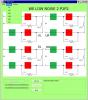
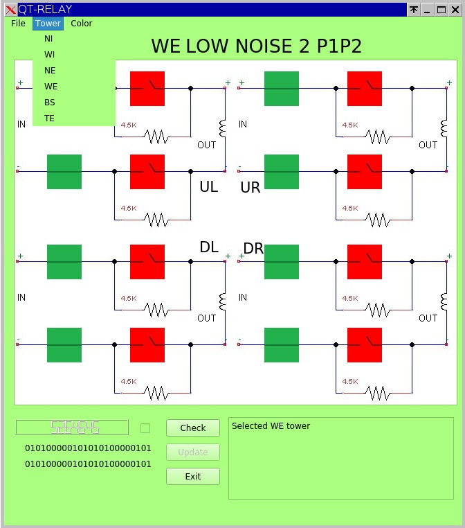
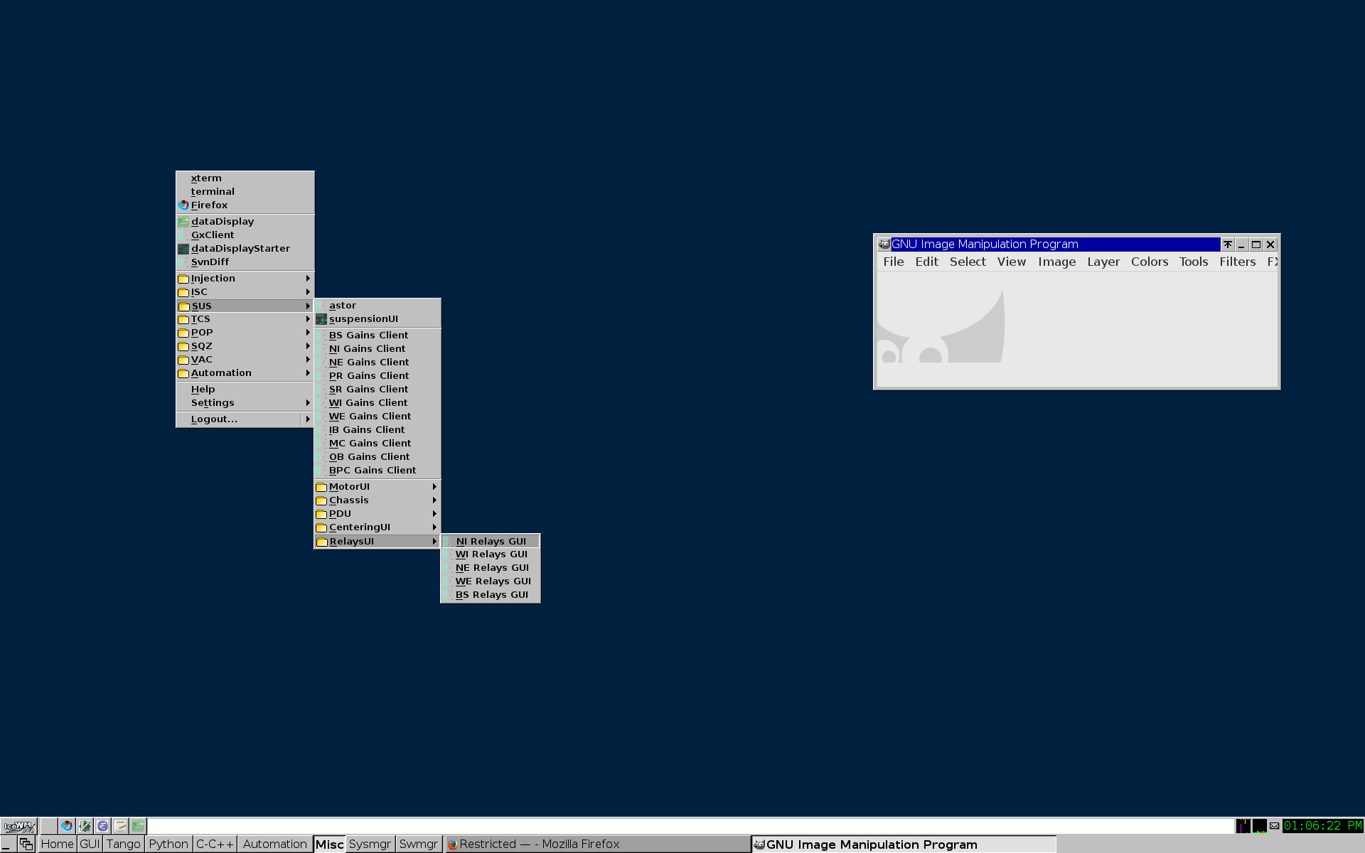
Due to the sistematical unlocks we experienced in the past while working and walking around the input towers on the platform, we decided to use a different approach respect to the one used for the End Test Masses: open only one arm of the Coils (using a dedicated relay box command via Giulio's GUI) and send a 15Hz line using the Virgo/Pisa DSP DAC. That way no current flows into the coil, and only electrostatic forces are exerted. The level of the signal written on the DAC was 1Vpk, then this signal goes through a "matrix" whose values ​​are:

NI UL  0.979
NI DL -1
NI UR -0.9218
NI DR  0.9429

WI UL -0.9208
WI DL -0.9634
WI UR  0.9574
WI DR -1

Here the summary of the test (readings on LSC_DARM using DataDisplay with T=10S):

COIL real Vrms amplitude 15Hz line 30Hz line
NI UL 0.6922 8e-6 1e-8
NI DL 0.7071 1.9e-5 1.4e-8
NI UR 0.6518 4.6e-6 1e-8
NI DR 0.6667 8e-6 1e-8
WI UL 0.6510 8e-6 1e-8
WI DL 0.6812 3.3e-6 1.2e-8
WI UR 0.6769 3.6e-6 1.3e-8
WI DR 0.7071 1.2e-5 1.2e-8

As a raw comparison with the old END mirrors measurements, we copy here the old values measured in LSC_DARM (they should be with the same T=10S)

COIL real Vrms amplitude 15Hz line 30Hz line
NE DR 0.884 1e-5 1e-7
NE UR 0.871 7e-5 1e-7
NE DL 0.871 7e-7 1e-7
NE UL 0.871 4e-6 1e-7
NE DL 0.871 8e-7 1e-7
WE DR 0.877 3e-6 7e-8
WE DL 0.877 5.8e-5 7e-8
WE UR 0.877 3e-5 7e-8
WE UL 0.877 2.4e-5 7e-8

The "2f" quadratic signal (30Hz) should be relative to the actuation when the mirror is not charged, while the "f" linear signal (15Hz) should be relative to the charged mirror: the old test at END mirrors had a 2f of about 1e-7 while in this test we read values around 1e-8. We need a cross-check that sends back this (new) type of signal to the END mirrors again, in order to validate and calibrate both measurements (the old one and the new one). Unfortunately this has not been possible, because the relais dedicated to the arm opening at END test masses are "hard wired" using a jumper. Removing this jumper makes the relay free for this use, but first of all we have to change some lines of code in metatron or ITF it will never lock again (relais always open).


We also have sent a signal 0.5Vpk and 2Vpk of amplitude (WI DR only), results are:

real Vrms amplitude 15Hz 30Hz
0.35355 5.6e-6 3.2e-9
0.7071 1.2e-5 1.2e-8
1.4142 2.3e-5 4.9e-8


Some relevant notes:

  1. the 50Hz feedforward has been left OFF during these tests, and consequently the 50Hz line grow also because having one arm of the coil floating seems to pollute more than usual.
  2. during our test we tried to open one arm of a coil, then to repeat the test with the other arm opened and the first one closed (e.g.: open DL+ and inject in DL-, and after that we reversed the configuration): the signal is sent to each arm through the simmetrical DAC output (one arm is driven POSITIVE, the other arm is driven NEGATIVE), and we noticed that the "sign" of the global 50Hz in DARM flips. This maybe means that the origin of this 50Hz signal is upstream?
  3. we also noticed that during measurements some non linearities arose in DARM: 35Hz (50Hz - 15Hz) and 65Hz (50Hz + 15Hz)


Conclusions:

It seems that also the INPUT Mirrors are charged. Difficult to say now if they are at the same level of the END, because the "2f" line that should not depend from the mirror's charge has not the same amplitude. We need further tests.


attached the LogFile 20190826 Input mirrors charge.txt

Non-image files attached to this report
Comments to this report:
G.Ballardin - 16:19 Wednesday 28 August 2019 (46791) Print this report

To launch the GUI mentioned by Federico, staring from an xterm:

> cd /virgoDev/Sa/QtRelay/v5/script/

> ./QtRelayMain.py  <NI|WI|WE|NE|BS>

or without arguments

> ./QtRelayMain.py

After, from the menubar, it's possibile to select|change the tower.

Images attached to this comment
carbognani - 13:11 Thursday 29 August 2019 (46797) Print this report
The QtRelay UI has been installed under:
/virgoApp/Sa/QtRelay/v5/
and added to the IceWM menu under the SUS -> RelaysUI tabs (see Fig. 1) so it can now be started from there.
Images attached to this comment
Paoletti, Ballardin, Boschi, Ruggi, Tringali - 16:25 Tuesday 08 October 2019 (47147) Print this report

After some modifications on relay boxes (see elog 46907) we managed to re-measure the charge of an ETM mirror (specifically: WE) in order to validate the whole new setup, and we also tried to summarize what we have measured up to now.

Note:

  • all values read in LSC_DARM (Nov. 2018, Aug. 2019 and Sept. 2019) have here been normalized to 1Vrms sent to one arm of each coil.
  • all measurements have been made in two way (when possible): direct measurement of DARM line amplitude, and Transfer Function (Excitation on the Coil / LSC_DARM); they both agree, but the second one allow to know the relative phase, useful for charge polarity guess

Quick conclusion: what comes out comparing old vs new measurements at WE mirror is that these two does not match for a factor ~2 in the effect of the actuation force (because we see a factor ~4 higher on the <2f> in the old measurement respect to what we read with the new one). This could be explained only with an error in the setup and/or in the level sent to the coils, but we have cross-checked many times, and we found no errors ... ( remember: the value <2f> does not depend on the mirror charge !)

Some words explaining the measurements done and the attached PDF document:

  • In November 2018, in the hurry of hunting for the 1/f^2.5 noise, we prepared a "quick and dirty" setup made with a high voltage Signal Generator (0 to 300Vrms), whose signal was reduced to 1Vrms, sent to each coil with a 10 MOhm series resistor, and read after it with a 1 MOhm input resistance floating oscilloscope. That way 1Vrms became about 0.9Vrms (the oscilloscope read 0.877Vrms).
  • In August 2019 we sent a 1Vpk signal using a DSP-DAC Suspension system, but passing through a recombination matrix whose value was between 0.9 and 1
  • In September 2019 we did the same, but going directly after the matrix, that way sending always 1Vpk

All the values ​​read in LSC_DARM have therefore been rescaled based on the signal sent.

In the attached PDF you'll find:

  • only the old values for NE mirror (red box) - we had no time to remeasure them with the new system, the interferometer was not collaborative
  • both the old and the new value for the WE mirror (green boxes)
  • only the new value for the NI and WI mirrors (black boxes)

Moreover for WE (new), NI and WI there is also the relative phase

We can only say that also the input mirrors are charge, and we can also say that the sign of the charges is not always the same, even in the same mirror.

Non-image files attached to this comment
Paoletti, Ruggi - 16:42 Monday 14 November 2022 (57754) Print this report

We were asked to redo some measurements on the charge of the cavity mirrors (if still present), just before (and then after) this week's scheduled venting.

The ITF was not very cooperative, so the test could only start after 12:30 UTC

We started with WI by applying a 15Hz 1Vrms line to just one arm of the UL coil. To do this we used a relay-code written by Giulio which can be found and launched in

  • cd  /virgoDev/Sa/QtRelay/v5r1/script
  • ./QtRelayMain.py WI

Note that applying a 1Vrms means that Paolo has to write 2.82V in the DSP card - we choose this specific frequency and level to comply to the previous measurements made in

https://logbook.virgo-gw.eu/virgo/?r=47147

We soon switched to 17 Hz because its harmonic fell into a less noisy DARM zone, and we also took the time to add a DC offset (this is a request from Diego Passuello: to have three times the same measurement for each coil: Sine, Sine + 1VDC, Sine -1VDC)

ITF unlocked soon after (through no fault of our own), locked again at 13:50 UTC - we decided to move to other towers with at least one coil measurement for each mirror, so in the order we tested at NI, then WE, and finally to NE (always UL coils).

The measurement ended after 14:30 UTC, where we left the ITF to the vacuum team who started the vent.

Log file is attached, the analysis will follow.

(N.B. the level at terminal coils was lowered to 0.071Vrms in order not to saturate DACs, due to the de-emphasis output filter)

Non-image files attached to this comment
Search Help
×

Warning

×