We investigated further the propagation mechanism of the vibration noise at 22.4Hz (nick-named "Vela killer") generated by the water chiller system used for the Virgo TCS lasers. The same system is being adopted for the advanced Virgo TCS lasers. We also tested what seems a pomising mitigation solution. We recall previous investigations identified the annoying noise source to be the fan cooling the chiller radiator and also excluded the noise propagates throuugh ground.
1) A sensor for measuring chillers water pressure noise
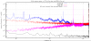
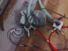
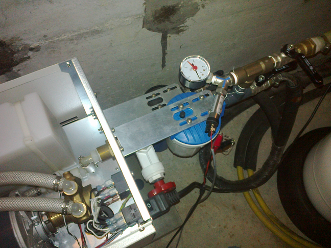
The fluid sensor transducer we used is of industrial-type: Keller, mod. PA-21SR piezo, "Sealed Gauge" type, 0-4bar range, 4-20mA output, 8-28V input. We installed a first such sensor (P1) at the outlet pipe just downstream of the chiller (Picture 1). We powered it at 24V DC using two car batteries serially connected, and we read the sensor output voltage across one 750 Ohm resistor. With this setup, the Voltage reading (Volts) corresponds to a "gauge pressure" (absolute pressure minus atmospheric pressure) of: P (bar) = Volts/3 - 1, which we roughly checked against a quad manometer (Picture 1). Figure 2 shows the spectrum of the measured water pressure fluctuation noise (blue) compared to the sensor (including power supply) self-noise (red) the noise pick-up by the cables plus the (battery powered) Onosokki spectrum analyzer (magenta) and the intrinsic noise of the measuring ADC (black). A a pair of narrow noise peaks at 22Hz (the mentioned fan) and 24Hz (the pump) are clearly detected with intensity of 10^-4 to 10^-3 bar/sqrt(Hz). These peaks are significantly above the probe self-noise (measured with chiller off) which stands at about 25microV (8 microbar) at 25Hz.
2) Tests with no water in pipes proof that noise propagates only when fluid is present
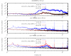
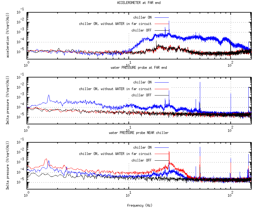
We instrumented the far end of the hydraulic circuit with another identical pressure sensor (P2) and one accelerometer (PCB mod. 393B12, 10V/g) rigidly clamped to the pipe termination (Picture 3). We first ran the chiller in standard condition (i.e. water coolant flowing along the - approx. 5m+5m long - hydraulic circuit). We then emptied the long circuit pipes and diverted the water along a short circuit by opening the return valve located just downstream of the "near" sensor (P1). We ran the chiller in this "empty pipes" configuration. Figure 4 shows water pressure noise at P1 (“NEAR”, bottom plot) and P2 (“FAR”, middle plot) and the acceleration noise at the far location (top plot): blue is with water, red is without, black is when the chiller is off. When pipes are emptied, no vibration noise reaches the circuit far end.
3) Softer rubber pipes dump considerably transmitted vibration
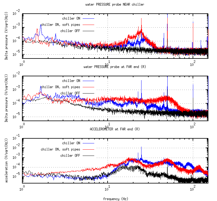
We replaced the original water pipes (5m+5m long, 20/15mm outer/inner diameter, made of canvas reinforced rubber) with ones of similar section (about 10% larger) and equal length, but made of softer more elastic rubber. Figure 5 shows the comparative test result. The vibration peaks at 22Hz and 24Hz, while still sensed by the close sensor (top plot) are no more detectable at both the far end pressure noise (middle plot) and vibration noise (bottom plot) sensors. A rough estimate is that the peaks amplitude reduced by at least 10 times. Far sensors still measure a broadband pressure and vibration noise excess when the chiller is on
(red wrt black). The spectral shape of this broadband noise at far end changes when slightly displacing the connector. This fact, as well as the absence of coherence between the close and far pressure sensors, might indicate that the noise originates from fluid turbulence which is produced locally.
4) Tappings give rough but consistent results
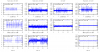
We tried simple finger tapping on pipes (chiller being off) as a rough easy way for comparative testing vibration noise propagation along pipes. Finger tapping on the pipe near the chiller produces pulses of low frequency noise content (about 10Hz) which are well visible in the near sensors. The pulses then propagate (or not propagate) along the pipes, and are eventually sensed by sensors at the far end. We did tappings test in all above configurations: (1) stiffer rubber pipes with and (2) without water and (3) softer pipes with water. Figure 6 summarizes tapping results. Old pipes filled with water transmit very well tapping pulses (actually fluid pressure pulses were even amplified at the far end, see first row of graphs); yet when these pipes were emptied pulses did not propagate sensibly (middle row). As well, softer pipes (water filled) look not to transmit tapping pulses (bottom row).

