Introduction: seismic vibrations at about 22.4Hz from the TCS laser chillers polluted the dark fringe at the Vela pulsar signal (27208) during VSR2. The problem was "patched" shifted the noise down in frequency by a few 100mHz by powering the chillers through a Voltage tranformer (27962).
This week we set in operation the NI TCS chiller (KODIAK mod RC006-H03BB3M246 SER.801898-01 by Lytron inc.) by closing (part) of the water circuit, as shown in Picture 1. Note that in this configuration the pressure load of the circuit is less than in its run configuration (the pipe total lenght is shorter and we closed just two out of three circuits). This might cause little differences in the noise frequencies with respect to the science run configuration.
We first performed measurements with one PCB 393-B12 accelerometer placed onto the pipe end which was laying on the concrete floor (see again Figure 1).
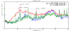
Figure 2 shows recorded spectra. We measure an excess of vibration of the pipe with respect to the floor between 10 and 80Hz, with three characteristics peaks: at about 22.3 Hz, 24.8 Hz and 49.6 Hz. This extra noise is clearly generated by the chiller, since it disappears as we switch it off (red versus blue in Figure 2). This measurement also demonstates that the noise does not travel through the floor, since
none of the peaks is present when the accelerometer is placed on the floor just neax to the pipe end (red vs green or black in Figure 2).
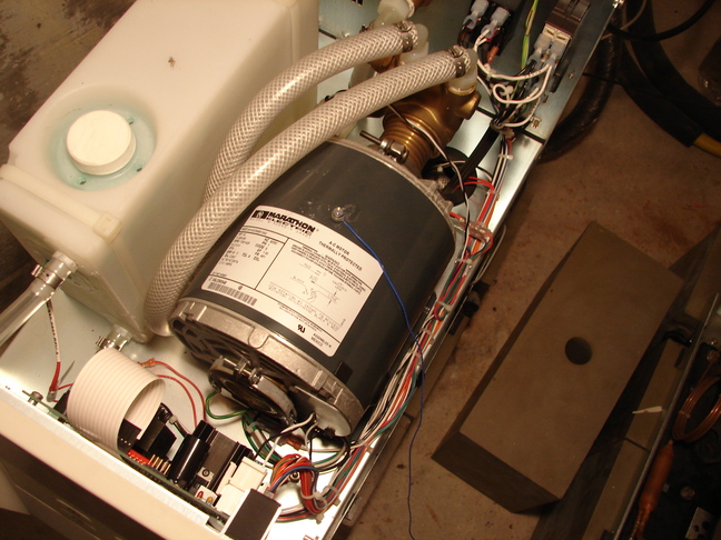
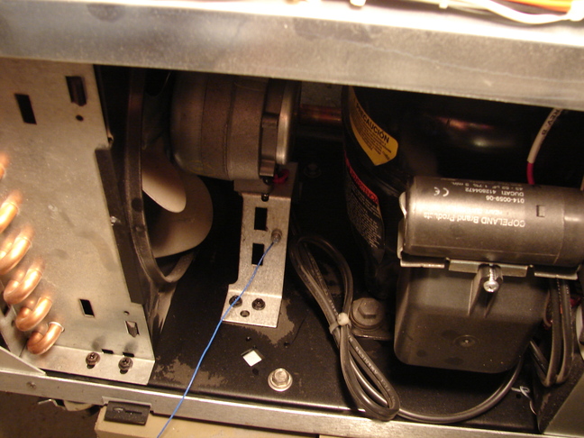
We then performed another set of measurements aiming to associate these peaks to a particular source inside the chiller. The chiller rotative electro-mechanical components are: one PUMP, Marathon electric AC-motor mod. 5kh32gnb813ax 1425 rpm nominal speed (Picture 3); one COMPRESSOR, Copeland mod. ARE27C3E (Picture 4); one FAN (Picture 5). A stobe lamp (NoOVA Strobe dbx) allowed us to measure the rotation of the fan (1339 rpm = 22.32 Hz) and the pump engine (1486 rpm = 24.77Hz) whose rotative part was visible. The lamp reading error (1rpm) is estimated as the lamp flash rate variation within which the illuminated object image is seen to reverse its motion.This measurement allows to clearly identify the source of the 22.3Hz vibration to be the FAN, and the source of the 24.8Hz to be the pump engine.
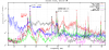
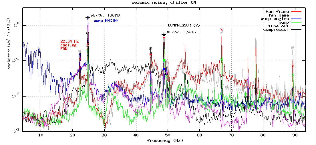
We also attempted a sort of vibration map of the chiller using one mini accelerometer (PCB 352B10) attached (wax) to various parts. Figure 6 shows a compilation of some seismic spectra. We can note the peaks mentioned above and harmonics. In particulare we note that the 49.6Hz peak sensed at the pipe end (Figure 2) seems to be the 1st harmonic of 22.3Hz (thus as well from the fan). We note also that most of the peaks are present in all locations with similar intensities. We have no clear evidence about the compressor vibration, although we might associate it the 48.7Hz who is orphan.
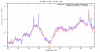
All above measurements were done with the chiller powered through the Variable transformer (elog 27962). Figure 7 shows what happened when we powered the chiller directly onto the mains. Just the 22.3Hz peak shifted (up by 0.2Hz) while the 24.8 and 48.7 Hz did not move. I do not have an explanation at the moment, unless it might have to do with synchronous vs async engines (??).
Few considerations:
- the most reasonable hypothesis seems that vibration noise propagates at distance through the water medium. This propagation seems most efficient for noise below 100Hz.
- it is not clear where the water picks up the vibration. Actually all the chiller parts vibrate with about the same amplitude at all interesting frequencies.
- Likely the pump vibration is unvoidable, as the water passes through it, while the water vibration at the fan frequency (indeed the vela killer!) might be reduced if we better seismically isolate the fan from the rest. Indeed, it might be margin for this since the fan is directry screwed onto the chiller box (see in Figure 5). Some isolating dumping rubber might be added (??)


