After the work done by Bulten and co on the EIB rebalancing with started to work on the realignement of the beam from PMC output towards the BPC quadrant with the EIB blocked in its nominal position.
To do so we locked the PMC with the reflection as a trigger. The LB_M13 is still a beam sampler that reflect only about 1% of the PMC TRA. The power was also reduce at the PMC input by about 50%. As a result we were working with a beam of about 350 mW to do the alignment.
We started by aligning the beam into the apertures which are at the output of the LB, using LB M13 and LB M14. While arriving on the EIB, we noticed that the beam was relatively low, few mm below the usual working point (100 mm). This is not completly explained, we checked the apertures at the output of the LB that were effectively at 100 mm. This discrepency can either be due to a height difference between the two benches or it means that we are not well aligned in the lens (f = 1000) at the output of the laser bench. The heght of this last an not be set.
We decided to keep the pinholes as the horizontal reference for the beam at the output of the LB but to use M13 and M14 to get a beam propagating in the 100 mm plan on EIB. We did so and adjusted the height of the apertures at the output of LB.
From here we started the alignement of the beam on EB by setting the miror EIB M1a M1b and M1c. We used M1a and M1b to ensure that the beam was propagating in the 100 mm plan and in the right direction for the transmission of M1c that will be used both for ALS and for the BPL loop. Once it was done we moved M1c by hand both in horizontal shift and horizontal tilt to pass through the EOM and eventually reached the photodiodes downstream ( BPC QN DC and QF DC for example). We managed to get the expected DC on both quadrants about: 0.006 V for 0.35 W of PMC TRA while we usualy have about 1V for 60 W of PMC TRA.
From here we started to work on the alignment of the optics downstream of M1c.
We noticed that we were very high on PT_M1, also the Y of the BPC was quite out of range.
This is explained by the fact that the algnment on EIB as alwas been done with a beam that was slightly lower.
We decided to go on with a general realignment on EIB. At first we got the beam back in the 100 mm plan in transmission of M1c, using M1a and M1b, and check that we were indeed correctly passing through the EOM.
Then we used EIB M3 to get the beam centered at the exit of IPC1/ M4. Then we used the mirrors one after the other till M8 to center the beam on each other.
We eventually got some signals on both NF and FF QPD (note for the future : IBJM is convenient to visually check the FF).
We will go on with the final fine alignment on monday.
Today we kept on working on the alignment.
First at low power and then we swap the LB M13 mirror that was reflecting only 1% of the power of the PMC transmission and put the nominal one that relfect it all.
Unfortunately we had to work again on the alignment but at high power. We managed to get a rough alignment with the PMC in scan at medium power (10W).
The beam was still low on the BPC QPD, we had to realign it by hand using M6 and M8. We eventually reach the values of TX TY X and Y that we had before starting the intervention.
There are still things to understand, especially the DC values of the PD and QPD that seems to be different, the IMC REFL seems to be different as well.
Side activity : we started to realign the beam inside the PMC diagbox.
1. Injection Line Alignment & Power Loss Investigation
We continued work on the alignment following suspicions of beam clipping in the EOM + FI + IPC section. Initial measurements revealed significant throughput issues:
-
Measured 50.4 W at the PMC output and only 24.2 W after EIB M5.
-
After rotating IPC1 for full transmission, power increased to 38.3 W.
-
Accounting for measurement uncertainties and the new BPL/ALS pick-off (~3%), we calculated total losses of 21%. This is significantly higher than the historical baseline of 10% (ref: 50224).
Realignment Actions: We performed a systematic high-power realignment. By optimizing the throughput at the output of the third EOM by moving EIB M1c and centering the beam through the FI and IPC using EIB M2/M3, we achieved the following:
-
Final Power: 39.4 W measured after M5 with 45.5 W at PMC TRA.
-
Final Loss: Calculated at ~14% (normalized via PMC TRA monitor: 39.4/45.5×0.566/0.572).
-
Outcome: Beam profile visually improved; alignment proceeded through the telescope to the BPC QPD.
2. INJ Recovery & Loop Status
-
BPC Board: Valerio and Marco investigated the BPC board. We are observing an unidentified saturation-like behavior on the PZT where it stops responding. However, by maintaining low PZT values, we successfully locked the BPC.
-
IMC Lock: After realigning SIB1 and the MC, the IMC was locked.
-
IPC1 Adjustment: Power was reset to previous levels by monitoring the IMC REFL signal in the unlocked state.
-
IMC AA : Locked in drift control. Need to work on the matrix with the new reflection
-
Current Status: The IMC reflection suggests a larger mode mismatch than previously observed. Transmission power is currently lower at ~15 W.
-
Pending: Investigation of mismatch causes (?)band fine-tuning of IMC loops (AA, PDH, offsets, and Transfer Functions).
3. Beam Pointing Line (BPL)
-
Set all optics in transmission of M1c.
-
Power Measurements: Found 20.5 mW on the FF QPD and 23 mW on the NF QPD. These values align with our theoretical expectations.
-
Pending: Verification of beam properties on both QPDs and functional checks of the QPD and PZT.
4. Additional Activities
-
PMC Diagbox: Performed fine alignment. Despite using the same mirror transmission as before, the monitor signal is limited to 0.62 V.
-
PMC Loop Stability: Reduced the loop gain to eliminate oscillations. This appears to have resolved the power fluctuations observed today
-
ALS: (See dedicated entry).
INJ recovery :
Power calibrations :
Having fixed the power fluctuations at the PMC output that were due to loop oscillation. We worked on the calibration of the photodiodes and power budget :
With 0.615 V on PMC TRA we measured 51 W at PMC output.
With 29.6 W measured after M5 we had 30.4 W on EIB_PD_out not.
With IPC1 at full power we had 41.4 W out of the 51 W at PMC output.
This means 1-(41.4/(51*0.97)) about 16.4 % losses in the EOM FI IPC line.
The losses are quite high but the beam does not seem to be clipped. A potential explanation could be the angle of incidence of the beam arriving on the TFP polarizers at the input and output of the faraday. They are quite sensitive to the aoi.
We tried to tune the HWP of the FI but it was already set to the maximum. Rotated them is not straight forward, we did not ush this investigation any further.
With 29.4 W measured after M5, we worked on the alignment and managed to get 18 W on IMC TRA. The power seen by the IMC TRA photodiode was consistent with the ones seen by the PSTAB photodiodes.
So it seems that we have an overall throughput of the IMC of the order of 18/29.4 = 0.61% which seems similar to what we had last time we measured the throughput losses (#67826)
By looking at the power on IMC REFL in locked and unlocked states and getting rid of the offset we have : (1.12−0.35)÷(6.38−0.35) = 12.8 % of the power which is reflected when we are locked with 18 W on IMC TRA.
Detailed study to make the comparision with previous power budget studies to come.
To be noted that somehow the DC values seen by the different PD and QPD have changed. This is a phenomena that has already been seen in the past and that could not be explained if not by the polarization somehow slightly rotating wile aligning on the parabolic mirrors and the IPC in front of the PD working closed to the full exctinction (#45306). We will investigate it and we will report the DC values to their normal working point.
Issues to be solved : BPC DSP non responding
Still to be done when the EIB will be suspended: close the IMC AA, potentially need to redo the matrix. General check of the loops. Updated throughput budget
BPL :
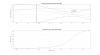
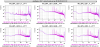
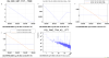
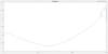
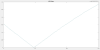
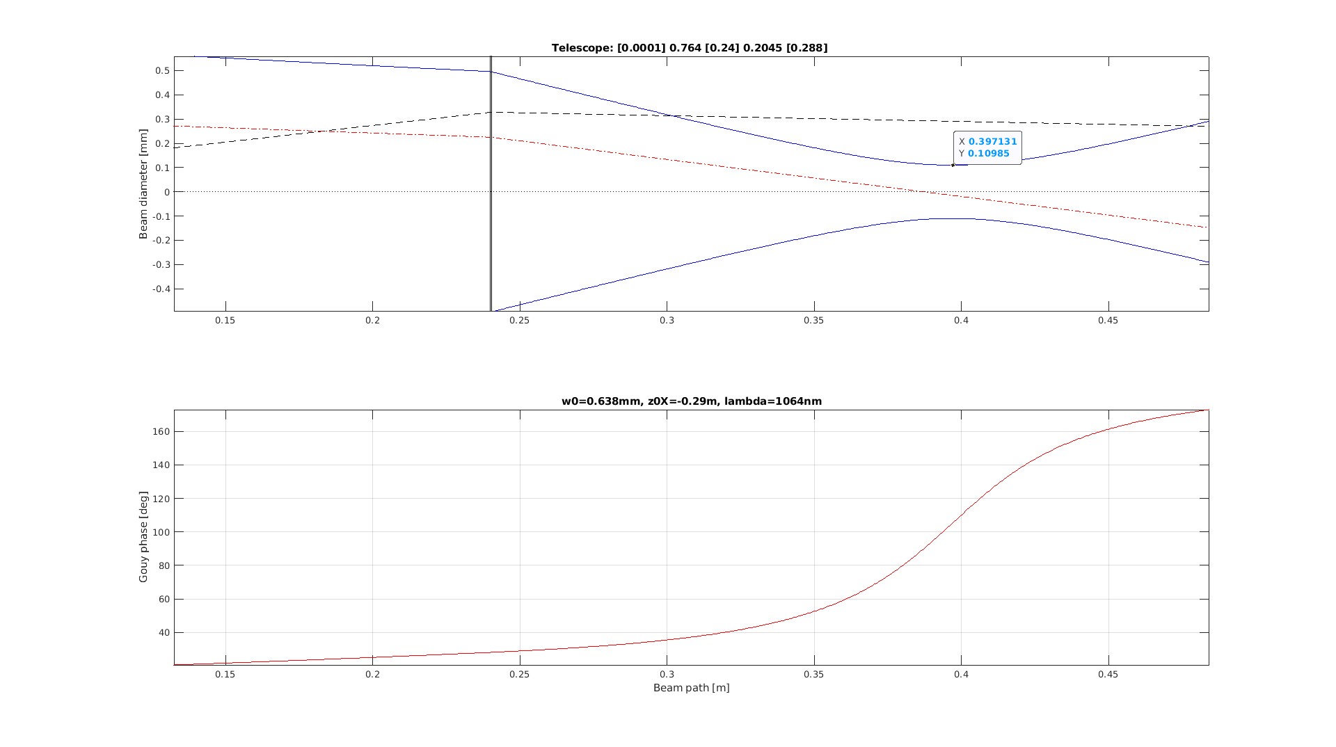
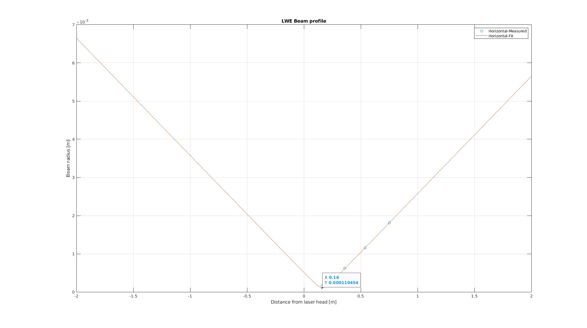
We measured the beam properties and they are has expected for both NF and FF about 400 um with accumulated gouy phase difference of 90 degrees (see plots).
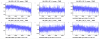
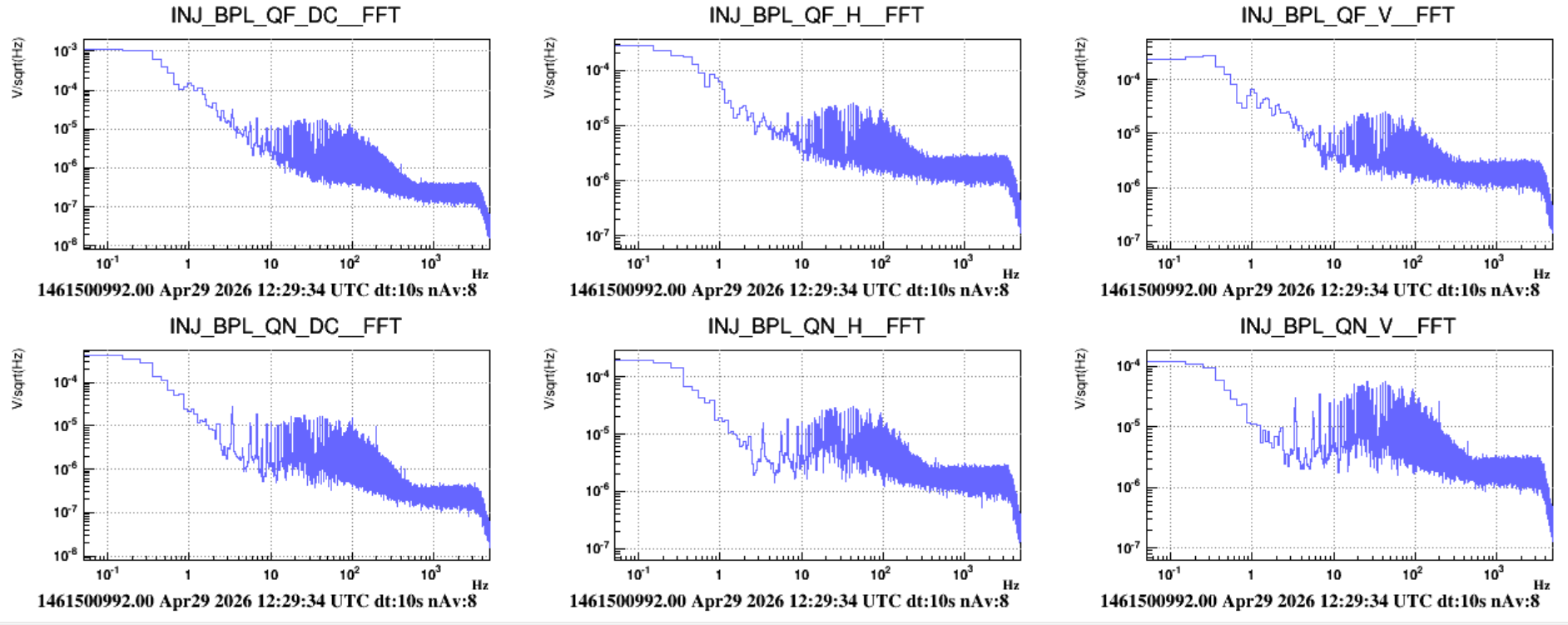
We power supplied the QPD and checked their behavior. For now they look quite noisy, especially the FF (see attached figure) but we should close the enclosure of EIB and suspend it before making any conclusion.
We could also see some resonance at 1.7 kHz with harmonics at 50 Hz that could be linked to one of the PZT.
Still to be done : Connect the PZT to the DAC and check their good functionning. Commissioning of the loop with EIB suspended.

INJ throughput losses on 10/04:
| Parameter | Value |
| EIB_out power | 30.9 W |
| Mismatch (IMC) | 7% |
| Throughput losses (IMC) | 34.9% |
| Other losses (VIR-0225A-18) | 0.5% |
| IMC_TRA power | 17.8 W |
| SIB1 losses (VIR-0339B-19) | 7.5% |
| ITF input power | ~16.5 W |
INJ throughput losses on 22/04:
| Parameter | Value |
| EIB_out power | 29.4 W |
| Mismatch (IMC) | 13% |
| Throughput losses (IMC) | 25.3% |
| Other losses (VIR-0225A-18) | 0.5% |
| IMC_TRA power | 18 W |
| SIB1 losses (VIR-0339B-19) | 7.5% |
| ITF input power | ~16.6 W |
Notes: comparing the budget before and after the Injection intervention, with the same IMC_TRA power we have a reduction of roughly 10% of the throughput losses, which is not something expected. We are considering that the EIB out photodiode had a good calibration before the intervention but this is probably not true. Also the working point of the IMC cavity is different and this is another uncertainty in the calculations. On the other hand, we have a higher mismatch (almost twice of what we had before) if the calculation is performed taking IMC_REFL_PD as a reference like in #50089.
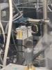
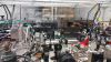
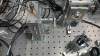
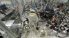
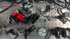
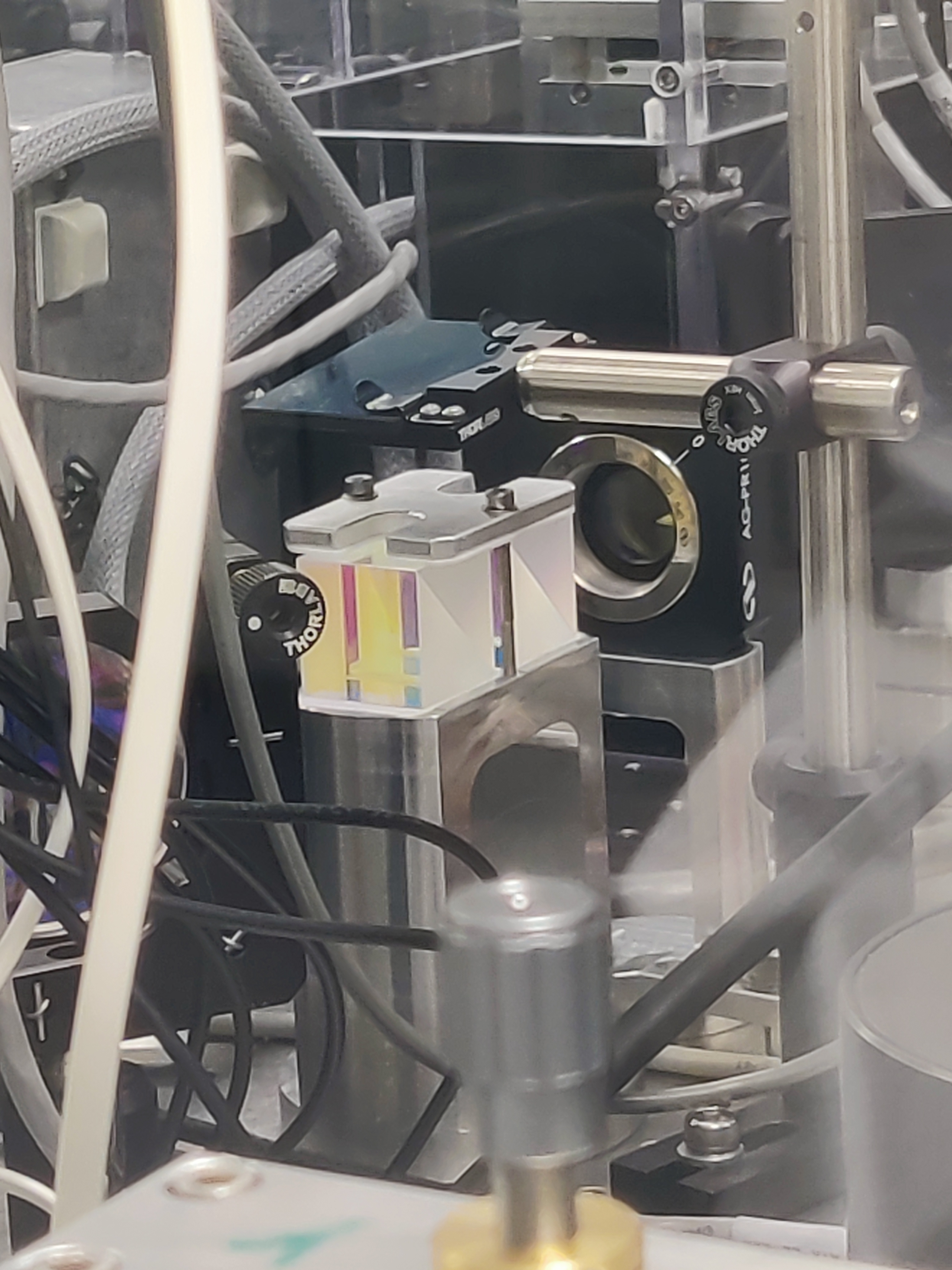
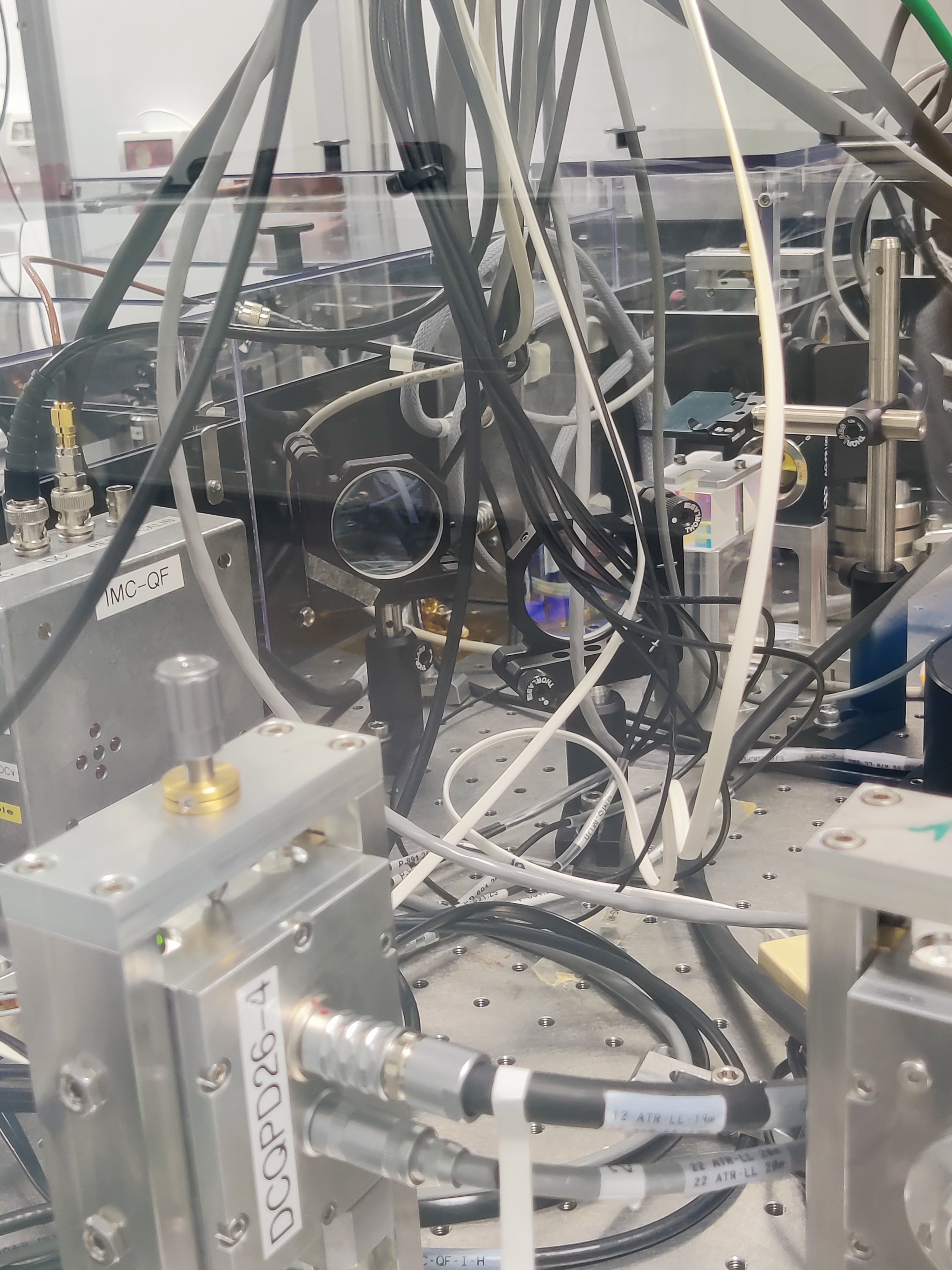
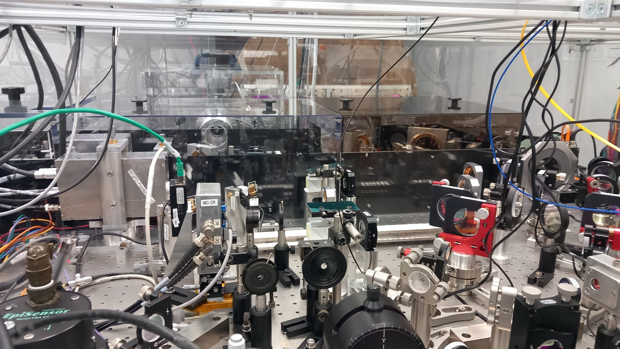
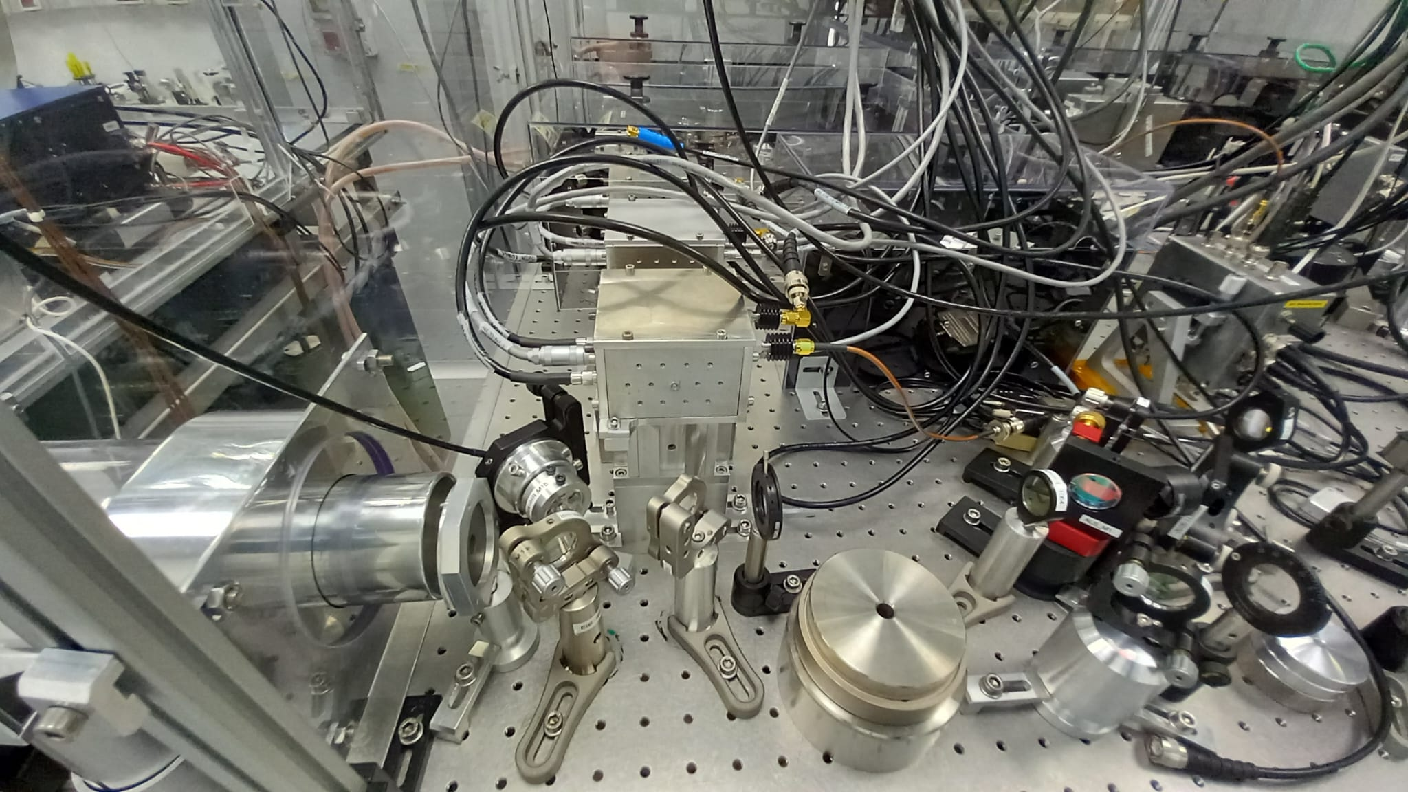
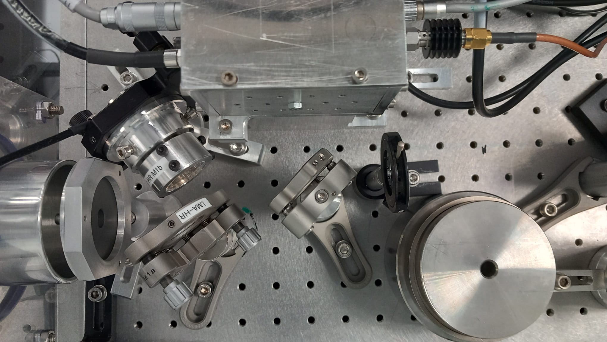
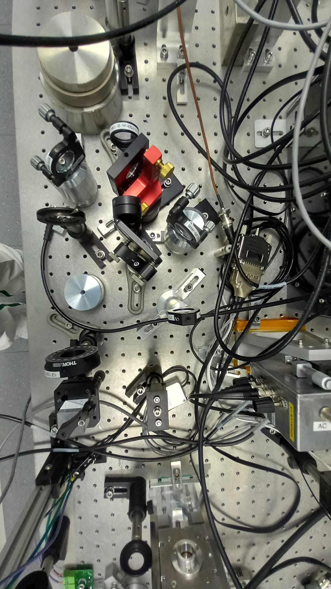
During the installation of the BPL we noticed that one of the IPC in front of one of the RF quadrant (the far field one) didn't have the beam dump to absorb the rejected polarisation, possibly causing stray light on the bench.
We did install an absorbing glass as for the all the other photodiode/quadrant IPCs (see fig. 1 and 2).
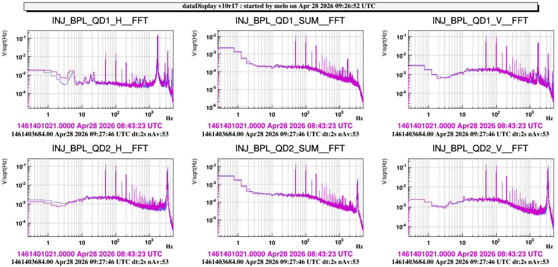
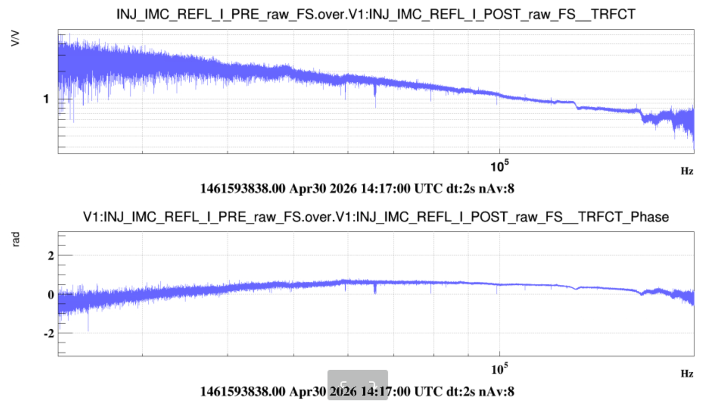
This morning around 8:50 UTC a resistance box provided by the electronic team was connected to the piezo driver controller of the BPL mirrors (INJ_BPL_QD1/2_H/V) in EEroom. Attached the FFT of the signals before and after installation.
In order to debug the new QPDs installed for the BPL loop, which show anomalous noise in both DC and asymmetries signals, we removed from EIB bench one of the new QPD (SN: DCQPD26-1) and from EAB bench the QPD used for IBJM (SN: DCQPD 4).
For the time being, EIB bench is blocked and the PMC in scan with the beam blocked on LB.
- today upgraded versions of the quadrant photodiodes for the bench pointing loop have been installed. In fact yesterday Piernicola and Flavio found out that the excess of noise on the QPD signals was probably due to the length of the cables.
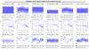
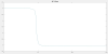
The two QPDs have then been realigned to have DC and asymmetries close to 0 (plot 1) and plot 2 shows the noise of the QPDs without any laser beam.
- In order to close the BPC we had to move the picomotors on M6 and M8 mirrors on EIB. We found that the driver for the M8 tx ty picomotors doesn't work anymore. We temporarly plugged M8 tx and ty on Far M1 ty an tx respectively. We could then close the loop
- we finally struggled to lock the IMC since we had not realized that the valve between SIB1 and MC had been closed (we thought the beam was misaligned instead).
Tomorrow we will continue with the INJ recovery and precommission of the quadrants on EIB.

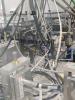
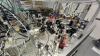
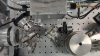
Here attached some pictures of the EIB after the installation.

- IMC alignment and measurement of the new AA sensing matrix
- IMC longitudinal wp. The offset on the IMC PDH error signal appears to be quite large (-1.6 V, see attached plot). However, with this offset the IMC lock is very unstable, so we left the old one -0.07 V. To be understood why the scan gives such large offset (maybe on monday we will check the alignment in the EOM? on the IMC refl photodiode?)
- IMC Fmoderr. We made it with the automation and it was very close to the optimal wp
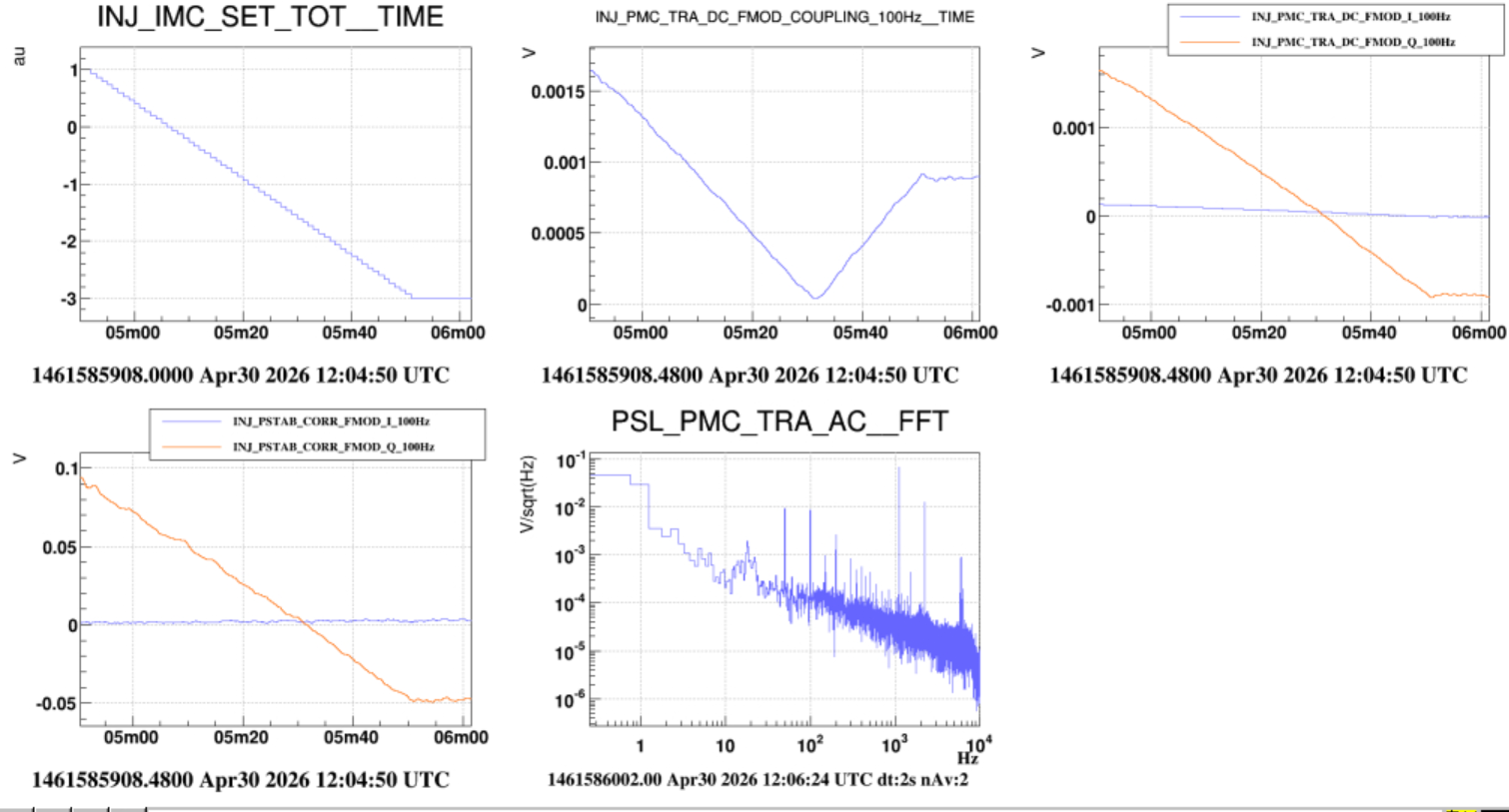
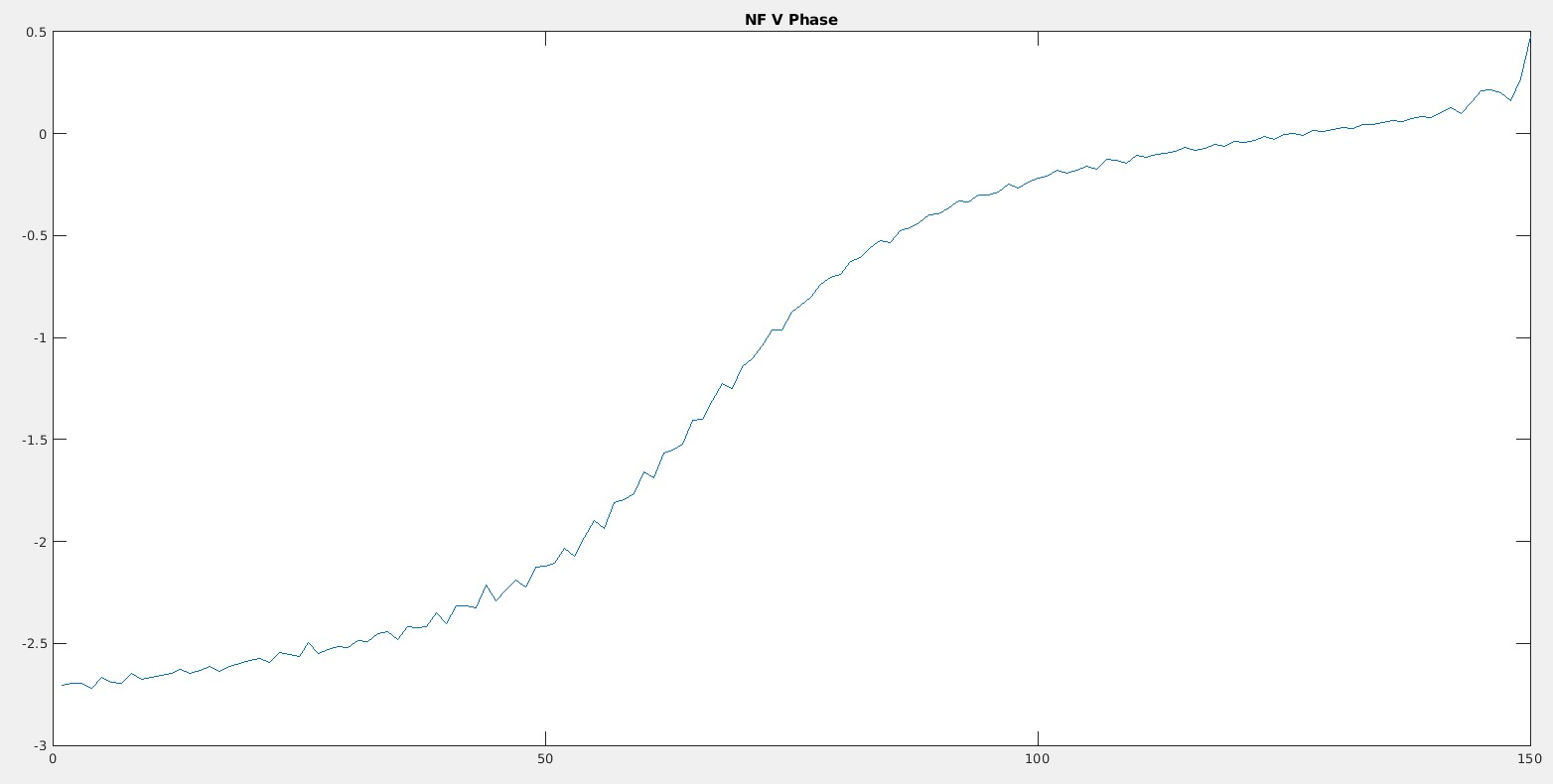
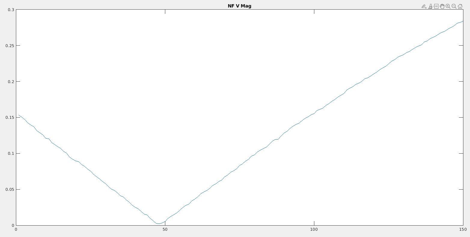
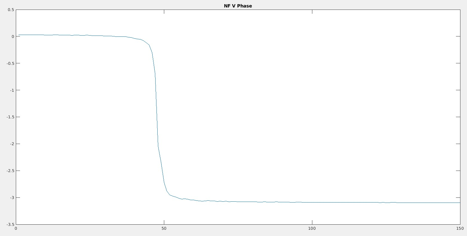
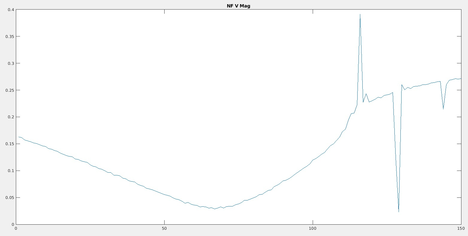
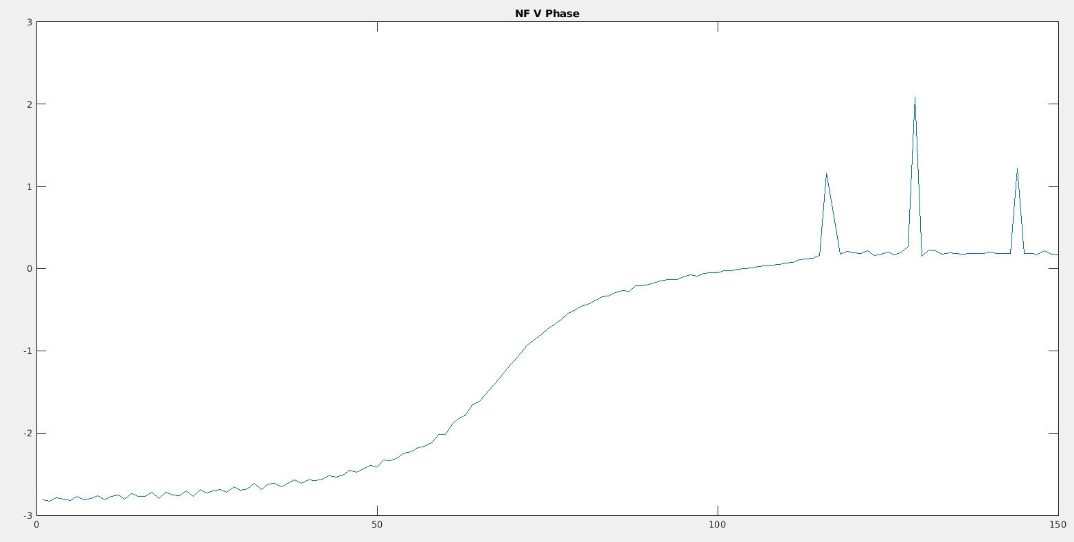
- IMC angular wp --> we found an issue on the NF V RF quadrant. We did the usual scans of the galvo working points (scanning the offsets of the galvos) and look at the coupling between error signal and frequency noise (TF between perturb at 1111Hz and the Quadrant signal (the demodulated quadrature I). We observed a strange behaviour for te NF V (non linearity: changes slope around the 0). See plots 2 and 3 which compare current scan (30 Apr 13:17:02 UTC) with an old one (10 Apr 2026 10:03:10 UTC): the magnitude doesn't go to zero and the phase behaviour looks strange. We then went in the LL Atrium and unpowered and powered again the NF QPD electronic box and made another scan at utc2gps(2026,04,30,15,05,08) from -0.5 to 0.5 in 300s (plot 6 and 7), which was still bad. To be investigated next week.
- IMC OLTF we found 96 kHz UGF and 30 deg phase margin. We added 1 dB to get 107 kHz and 23 deg phase margin (plot 8)
In the meanwhile we prepared the Acl code ISYS_BPL for the bench pointing loop. We still have to plug the PZTs to the DAC (we need prior to find a solution to block the beam before the EOMs while testing the PZTs, since the risk would be to burn something)

