Reports 1-1 of 1 Clear search Modify search
AdV-TCS (Point Absorbers Mitigation)
corubolo, nardecchia, ballardin, buggiani, erbanni, kraja - 18:44 Tuesday 14 April 2026 (68992) Print this report
WI PAM Installation - Monday, Tuesday

During Monday afternoon:

  • The alignment plates were retrieved from the washing room.

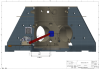
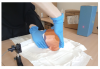
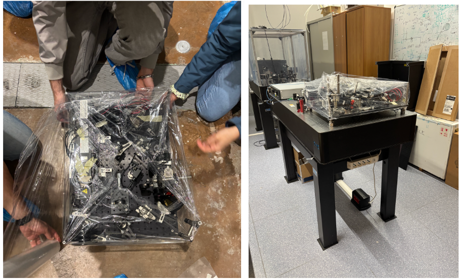
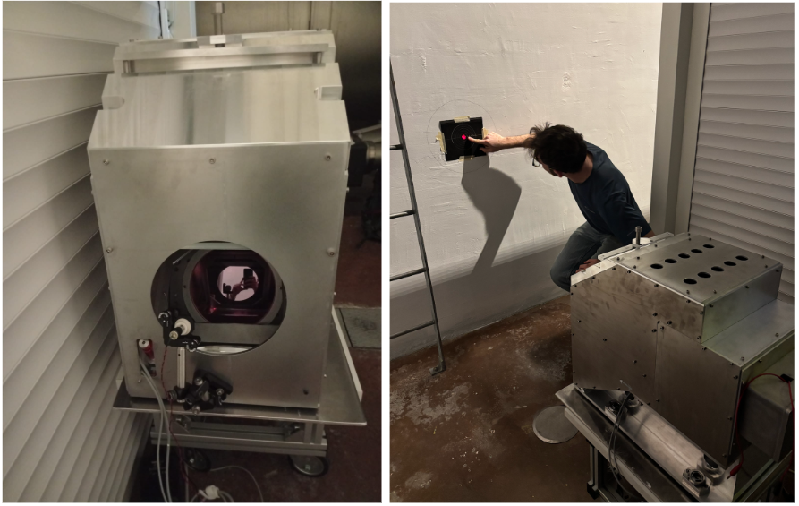
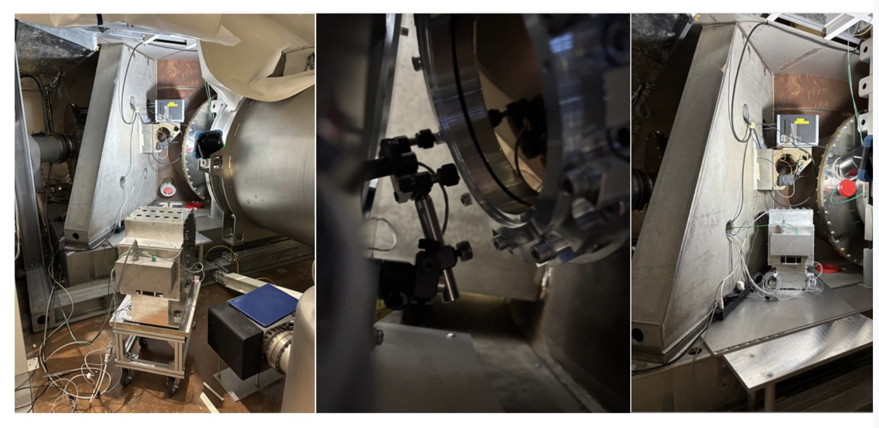
  • The IPATSiA optical bench was moved from the WI tower base to the optics lab (see Fig.1)

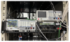
  • In parallel, the cabling of the picomotors was carried out in the TCS room by Giulio and Elian

On Tuesday:

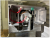
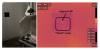
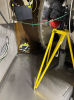
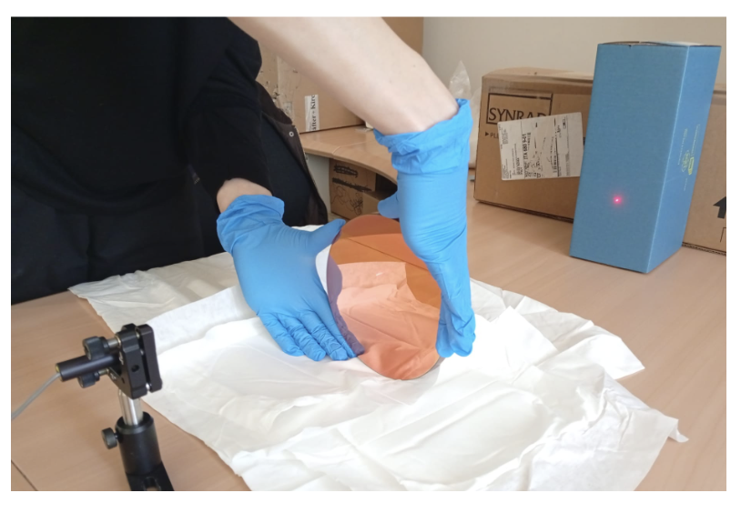
  • The alignment plate was installed on the WI tower base together with Alessio B. and Angelo (see Fig. 2)

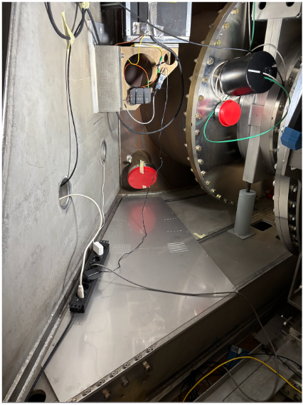
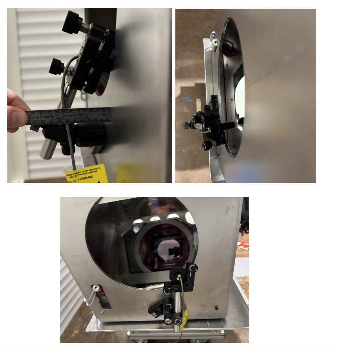
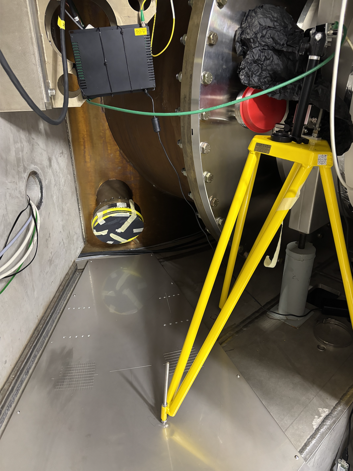
  • The LED setup used to ease the alignment on the HR surface was also integrated on the actuator (see Fig. 3).

  • The picomotors were cabled on the actuator side using CABLE 003 (TX) and CABLE 004 (TY).
    Finally, a remote driving test of the picomotors was performed with Giulio, confirming proper operation.
    Specifically, from the VPM interface:

    • TY+ → move the beam to the right on the HR face
    • TY− → move the beam to the left on the HR face
    • TX+ → move the beam upward on the HR face
    • TX− → move the beam downward on the HR face
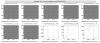
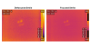
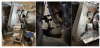
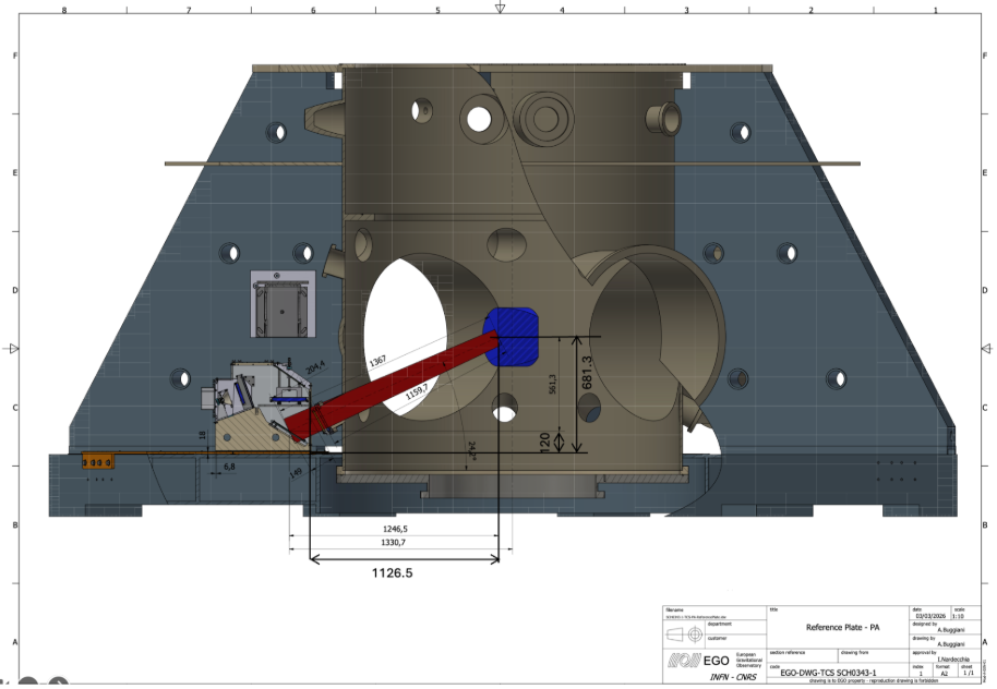
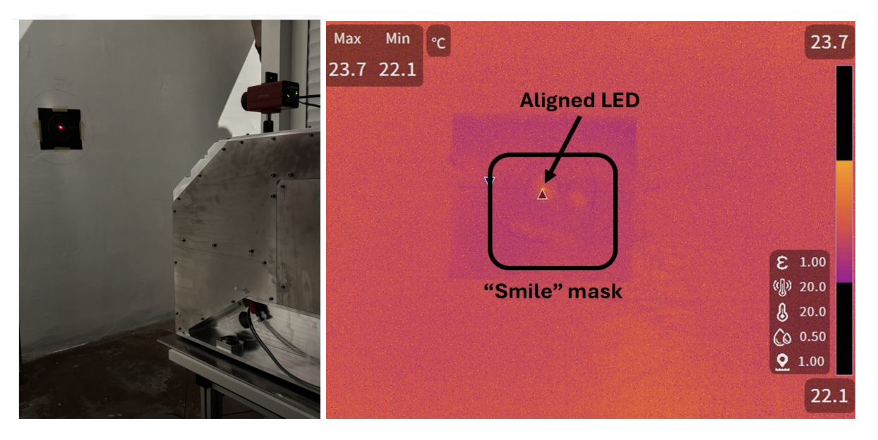
  • Then, the picomotors have been calibrated using the LED to the nominal actuator-TM design distance [Actuator–TM distance = 1126.5 mm | Height between the actuator base and TM center = 681.3 mm, as shown in Fig. 4].
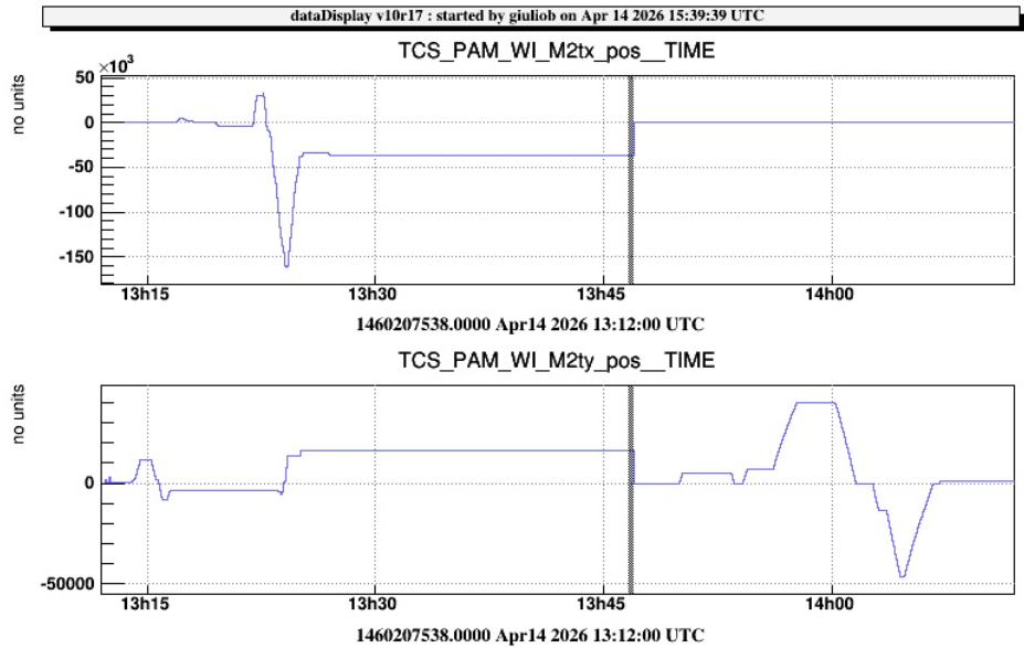
    We estimated:

    •  1 cm on TY =6666 steps
    •  1 cm on TX =5555 steps
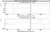
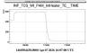
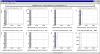
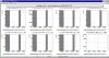
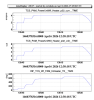
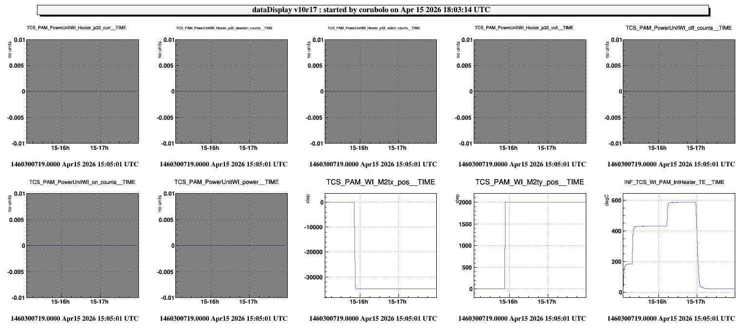
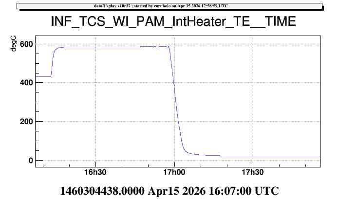
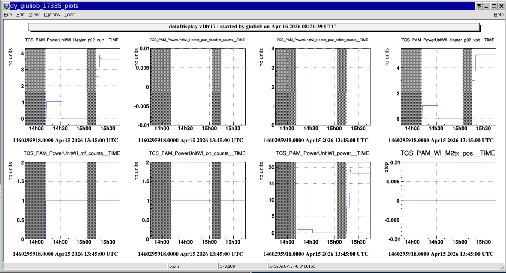
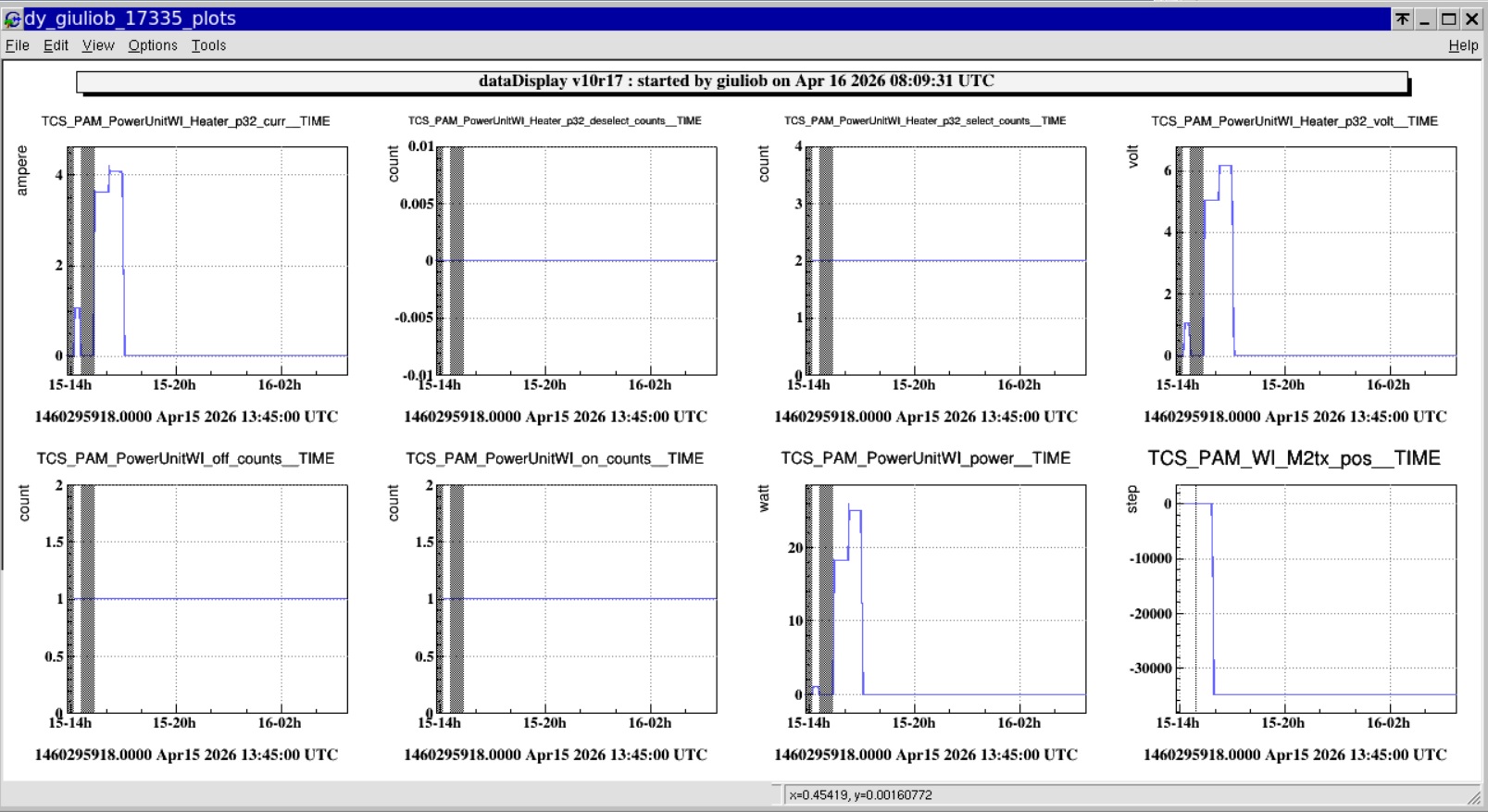
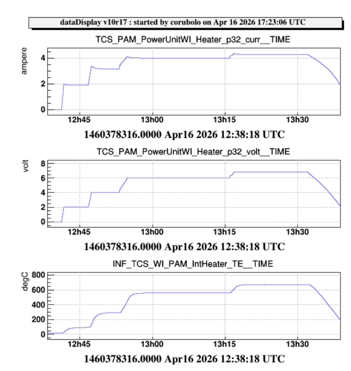
  • The movements of the picomotors are available on DD (see Fig. 5).

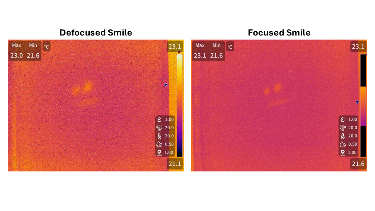
Tomorrow, we plan to complete the final cabling of the source and to align the thermal radiation to the red LED.


Images attached to this report
Comments to this report:
corubolo, nardecchia, ballardin, cavalieri, kraja, nenci - 20:21 Wednesday 15 April 2026 (69000) Print this report

Roberto and Federico completed the cabling of the WI PAM source, both at the actuator level and in the TCS room, to provide power and enable temperature monitoring (see Fig. 1).
The temperature of the heater is available under the channel INF_TCS_WI_IntHeater_TE.
 
In the afternoon, Elian completed the ethernet cabling for the WI PAM power supply in the TCS room, while Giulio set up the process on the VPM to control the switching on and off of the WI PAM actuator by setting the desired voltage (see Fig. 2).

Giulio also integrated the data to monitor the applied voltage, the current drawn by the actuator, and the applied power, which are now available on DD under the following names:

  • TCS_PAM_PowerUnitWI_Heater_p32_curr
  • TCS_PAM_PowerUnitWI_Heater_p32_volt
  • TCS_PAM_PowerUnitWI_Heater_p32_power

! The data are available online but we are not able to see them in the DD (see Fig. 3).

After completion of the cabling activities, the following actions were performed:

  • Alignment of the LED with the thermal radiation emitted by the heater

  • Installation of the alignment mask (“smile”) in the optical path and verification of its focus at the nominal position of the WI HR surface. Figure 4 shows the “smile” for lens L2 in two configurations: the left image corresponds to a non-optimized lens position, while the right image shows the smile in the optimized lens configuration.

The actuator was operated at V = 6 V and I = 4.1 A and the temperature of the heater reaches 600 °C (see Fig. 5).
Tomorrow we will proceed with the final positioning of the WI PAM actuator on the tower base.

Images attached to this comment
ballardin - 15:47 Thursday 16 April 2026 (69003) Print this report

The TCS_PAM_WI_PowerSupply server was launched yesterday at 13:45 UTC. Data has been archived to the DAQ since 14:10 UTC. For unknown reasons, after 15:00 UTC, there is a data gap of about 10 minutes (see figure1). After that, everything seems to be working properly (see figure2).

Images attached to this comment
corubolo, nardecchia, ciardelli, gherardini, spinicelli - 20:16 Thursday 16 April 2026 (69006) Print this report

THURSDAY 

WI PAM 
This morning, we replaced our LED with one kindly provided by the EGO optics group, as the one we brought from Rome was too weak and might not have been visible inside the tower. To be on the safe side, we also verified that the red LED light passes through the ZnSe viewport using a spare window (see Fig. 1). After that, we switched on the heater to align the beam with the new LED.

We then proceeded with the installation on the tower base. During the installation, it was noticed that the LED mount prevented the actuator from reaching the nominal distance to the viewport. The actuator was therefore removed and the LED mount was modified (the final configuration is shown in Fig. 2). At this stage, the LED was realigned to the thermal radiation by applying V=6.8 V I=4. 2 A reaching a temperature of about 670 °C (see Fig. 3-Fig. 4).

The installation on the tower base was then repeated and successfully completed (see Fig. 5). Once the actuator was correctly positioned, it was secured to the alignment plate using clamps.

The cabling, including the remote powering of the actuator and the operation of the picomotors, was tested after completing the installation.

The WI PAM actuator was left OFF, with the power supplies ON, the maximum current set to 8 A, and the output voltage disabled (see Fig. 6).

NI PAM

At this stage, we moved to the NI HR side. The NI PAM was removed in order to install the alignment layers on the tower base. To perform this operation, the tripod supporting both the camera and the thermal camera was moved. The alignment plate on which the tripod is now placed has a thickness of 18 mm; therefore, both cameras need to be realigned and refocused (see Fig. 7).
The NI PAM was left near the NI CO₂ laser bench, inside the white tent marking the laser hazard area.

Images attached to this comment
Search Help
×

Warning

Error

The present report has been modified outside this window. Please check for its integrity in the main page.

Refreshing this page will move this report into drafts.

×