We performed several tests on the NI Point Absorber actuator observing various issues affecting the picomotors. It’s still unclear whether the origin of the problems is hardware-related or due to the VPM control interface. Here's a summary of what we found:
1) End-Stop Behavior
When the motors reach the end-stops, the step counter on the VPM freezes and displays unrealistically large numbers (10–11 digits).
To recover the functionality, the following manual procedure is required:
-
Access the actuator physically.
-
Rotate it in the opposite direction (away from the end-stop).
-
Power-cycle the motor driver in the TCS room.
- Restart the VPM process.
Only then it is possible to control the motors remotely again.
2) Movement Blockage
In some cases, motor movement stops without reaching the end of the range.
In this scenario:
-
The interface does not crash.
-
Step counter values appear normal.
-
However, the motor doesn’t move (checked by eye and on the interface, the step count remains fixed).
Some offline tests will be carried out in the lab using the manufacturer's dedicated software to determine whether the issues with the picomotors are hardware-related or originate from the VPM interface.
3) Verification of Motor Labeling and Motion Direction
We verified the actual motion directions of the motors with respect to their labels in the control interface. Here's what we found:
-
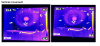
The motor labeled TX in the interface — located at the top-left when viewing the actuator from the rear (cable marked 001) — is responsible for horizontal movement of the beam (left ↔ right).
-
Negative direction (−): counterclockwise rotation → the beam moves left
-
Positive direction (+): clockwise rotation → the beam moves right
-
-
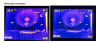
The motor labeled TY — located at the bottom-right when viewing the actuator from the rear (cable marked 002) — is responsible for vertical movement of the beam (up ↕ down).
-
Negative direction (−): counterclockwise rotation → the beam moves down
-
Positive direction (+): clockwise rotation → the beam moves up
-
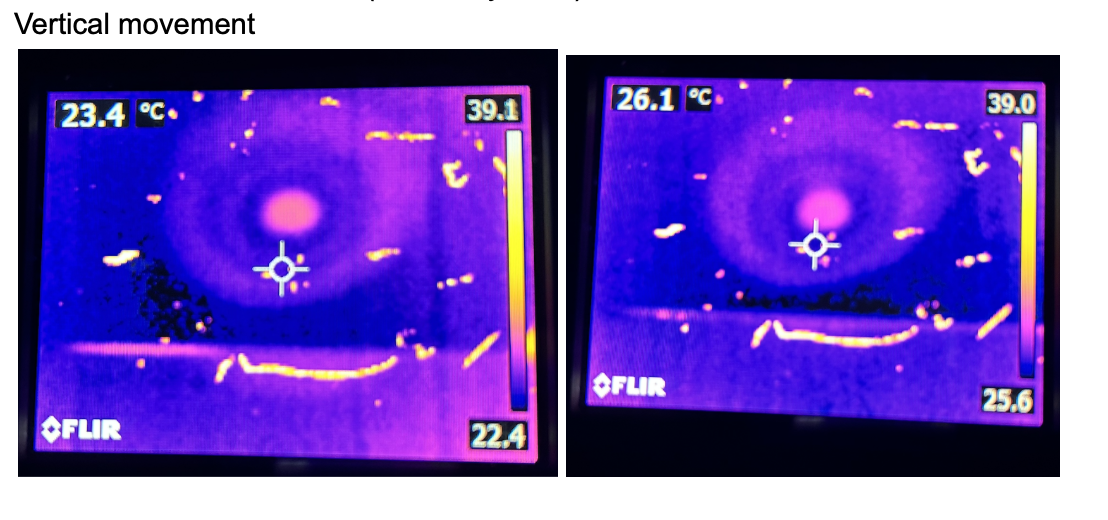
We confirmed these movements by placing a black cardboard ~22 cm in front of the actuator and observing the beam displacement in vertical and horizontal directions(see fig.1 and fig.2).
TO BE FIXED.
Current Status:
At the end of the tests, motion in the negative direction (CCW) is no longer working for either motor. Together with Bea, we manually brought them back to approximately mid-range.
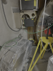
At the actuator level, the picomotor cables were disconnected from the actuator. The thermocouple and heater cables remain connected.
Figure 3 shows the NI PA actuator at the tower base, left in its current configuration.
In TCS room:
- the picomotors drivers were switched off and power supply cable disconnected
- the thermocouple reader and the heater were switched off and power supply cables disconnected.
Some notes:
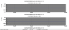
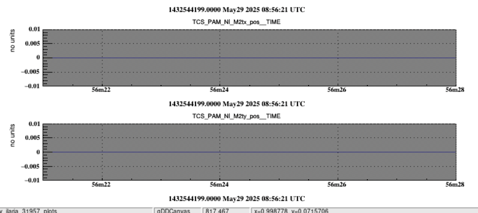
1) Currently, the Data Display (DD) channels are present but appear inactive (greyed out) when plotted (see fig.4).
2)It would be useful to implement feedback signal acquisition to confirm that the motors actually move in response to command inputs.
