Today we tried injecting a signal on WE Ring-Heater, reading the signal on the mirror coils (SC_WE_MIR_VOUT).
This is a very relative test: it may give us indications of some asymmetry in the four coils, following the analysis made by Michal in entry #66736.
To perform this test, we used a balanced BF generator isolated from ground, so that it mimicked fairly well the behavior of the power supplies used to power the RH.
As a test signal we generated a 3 Hz square wave, with an amplitude of 1Vrms (and then 5 Vrms), but since the RH is a non-standard load (30 Ohm), the reading on the generator display is relative.
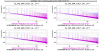
At first we sent the signal by leaving the connections of the two RH windings as we found them, and we were able to see the signal in the voltage monitors of the four coils, more or less equal between them.
At the end of the tests, we reconnected everything as at the beginning.
Preliminary conclusion:
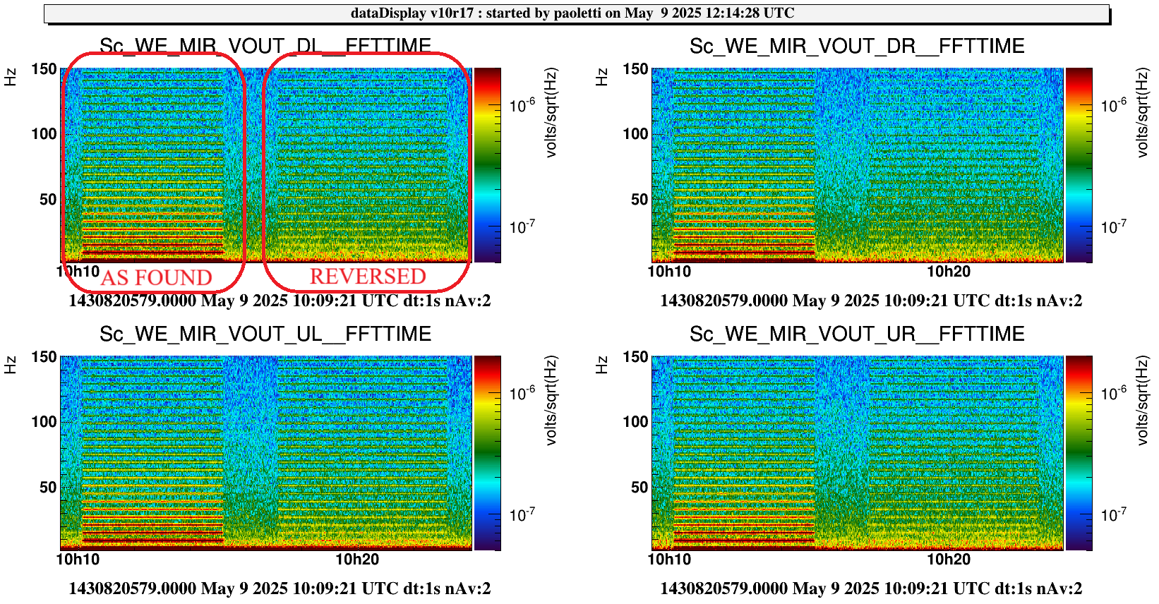
1) we did not notice any obvious differences in the signal seen by the four coils under any condition of the test.
2) It is likely that, although care was taken at the beginning of the installation of the RH (years ago) to respect a certain phase necessary for noise reduction, some unintentional inversions occurred during the last interventions on the WE mirror (to be verified).
3) it seems the reduction of the noise is effective only up to 100 Hz , maybe for some "capacitive" asimmetries (just a guess) - we stress again on this relative measurement: the good one will be having again the ITF locked, and looking at Hrec.
It is worth noting that on the air side it is very easy to put things back in place with the good phase, because you only need to reverse the connection of one of the two windings on the power supply connector.
Now, at the first ITF relock, we should see the 3 Hz comb again; then reversing one of the two connections should reduce it.
Once the sensitivity of the ITF has been recovered, it would be worthwhile to do a new test of injecting a known signal into the RH while the ITF is locked, so as to understand the real coupling with Hrec.
