Reports 1-1 of 1 Clear search Modify search
AdV-TCS (Ring Heater)
magazzu, nardecchia, tringali, was - 13:27 Sunday 04 May 2025 (66702) Print this report
WE RH Shutdown and Cable Disconnection for 3 Hz Comb Noise Investigation

After the RH was switched off in LN3 at 08:26 UTC, no changes were observed in the 3 Hz comb.

Since we were still in LN3, we agreed with Maria and Michal to try disconnecting the RH cables to check for any effects on the 3 Hz comb. Andrea went to the WE to perform the operation. The sequence of actions is listed below:

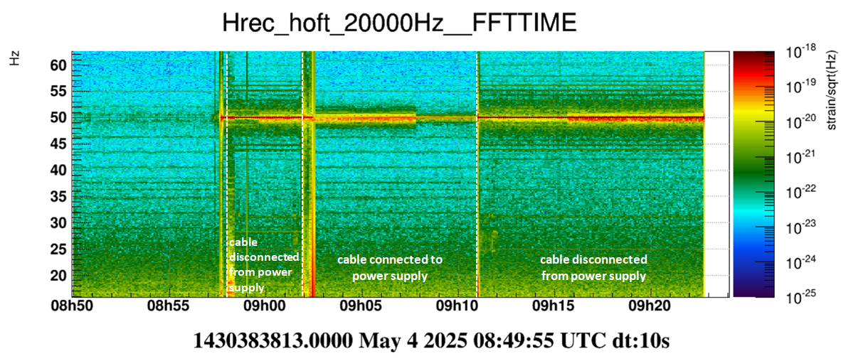
  • 08:57 UTC – RH cables unplugged from the power supply (still powered, but output set to 0 V).

  • 09:02 UTC – RH cables replugged.

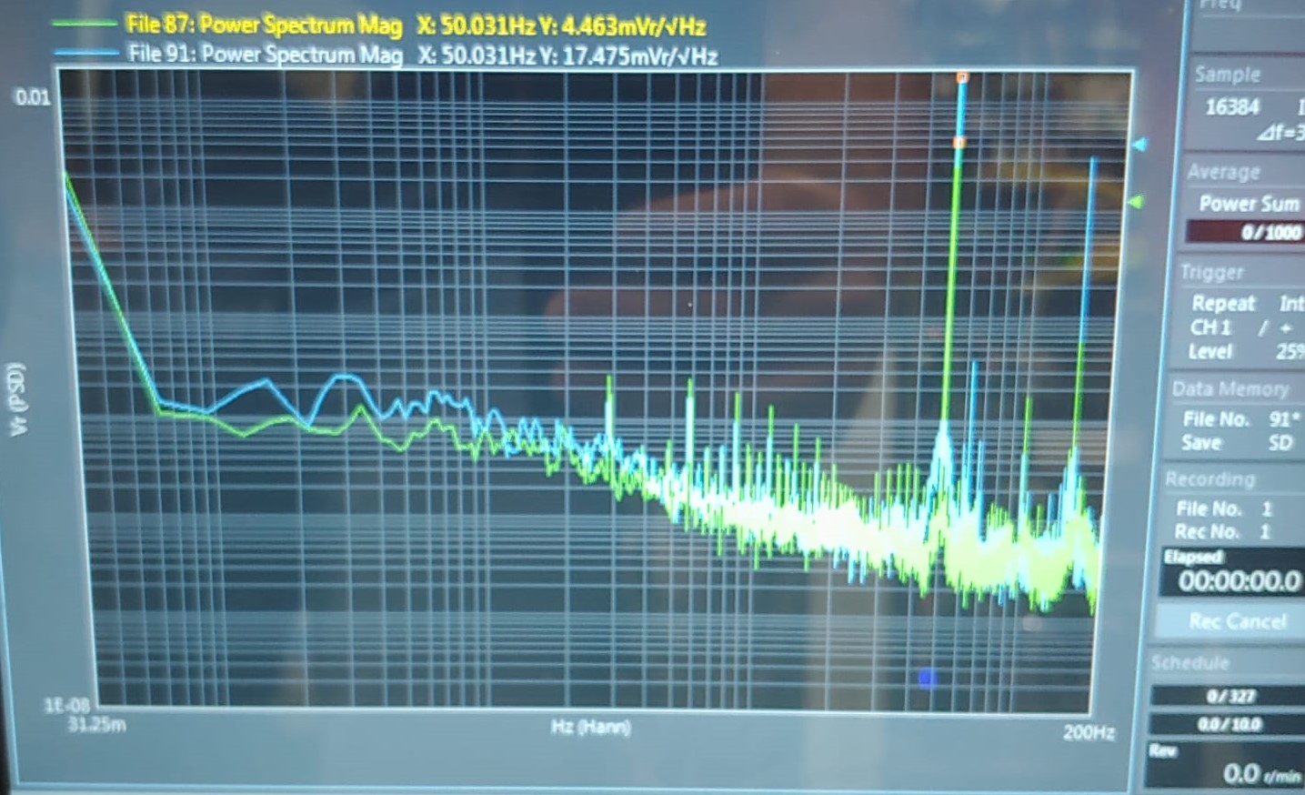
As  observed in other tests, the 50 Hz increased significantly (see entry 63151).  However, some peaks of the 3 Hz comb disappeared or showed a reduced amplitude.

To confirm the results, we repeated the test:

  • 09:11 UTC – RH cables unplugged again.

  • 09:22 UTC – ITF unlocked.

The same behavior as in the previous data segment was observed:

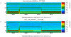
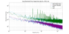
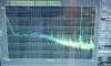
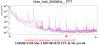
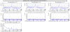
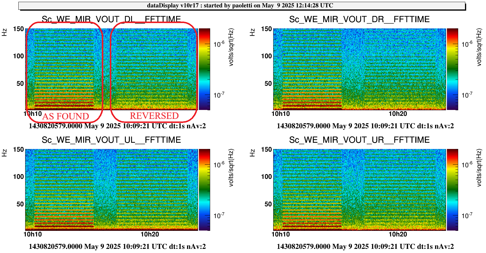
  • Figure 1: Spectrogram covering the entire test duration.

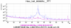
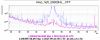
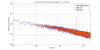
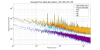
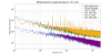
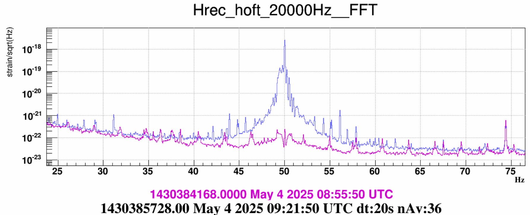
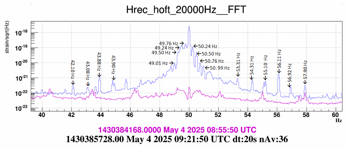
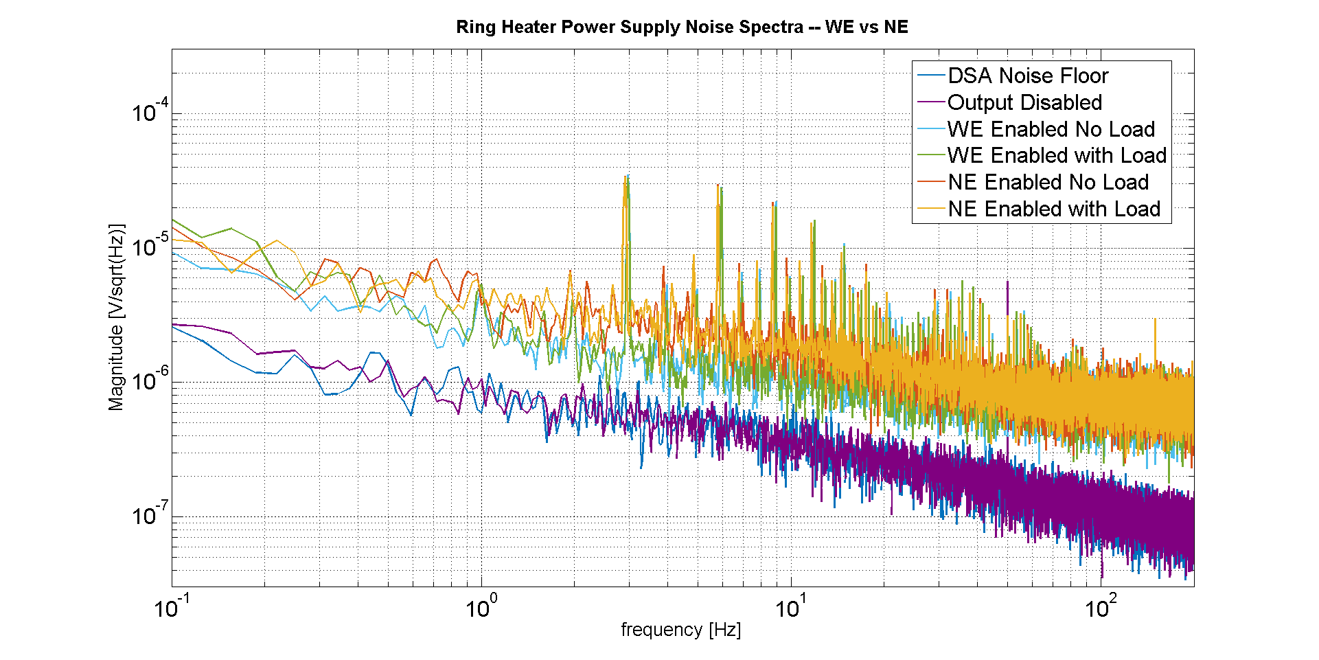
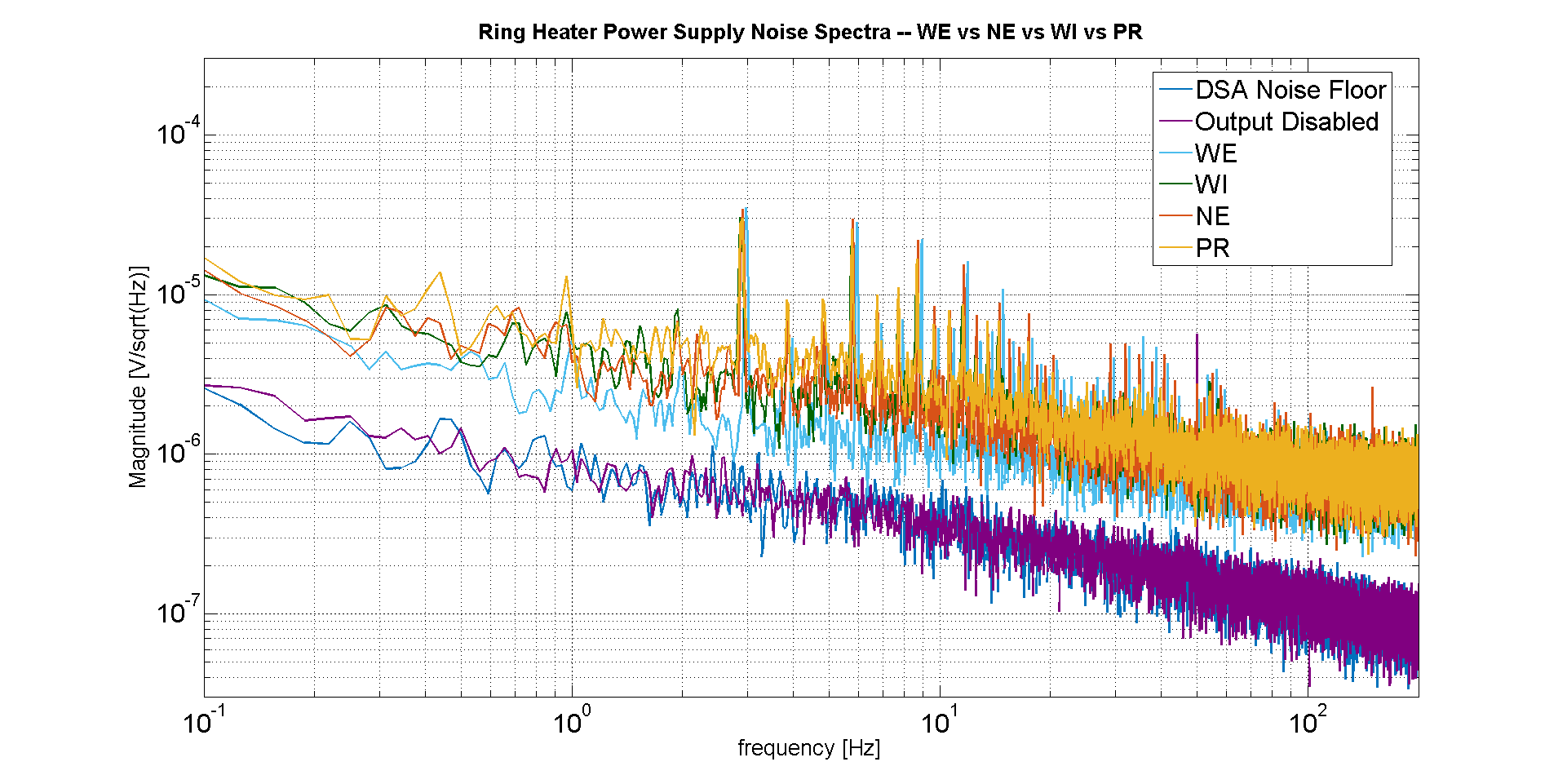
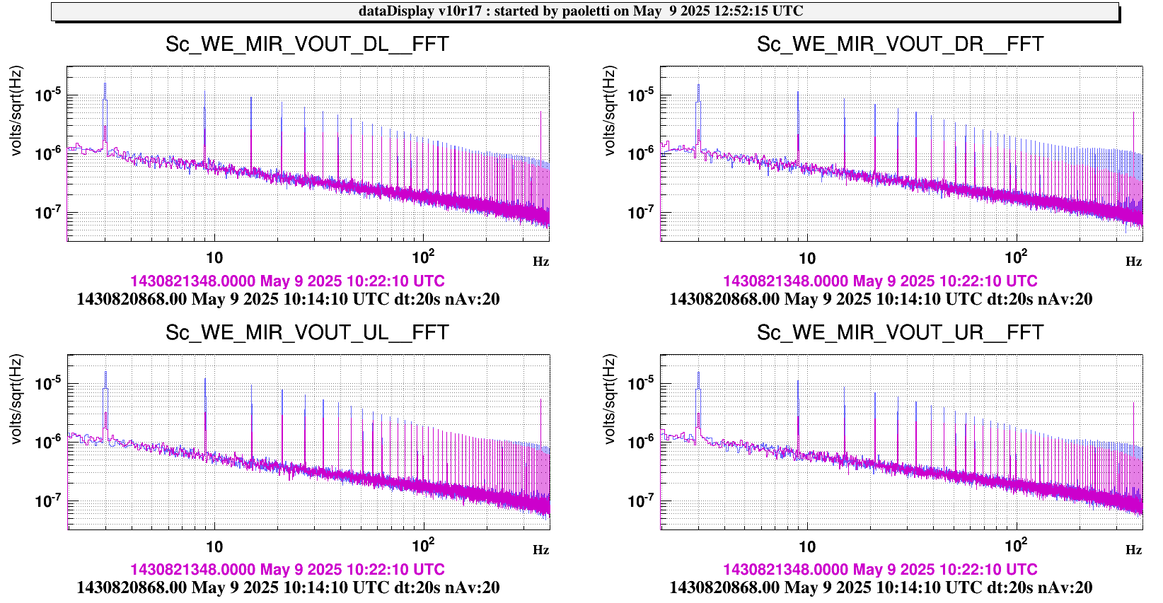
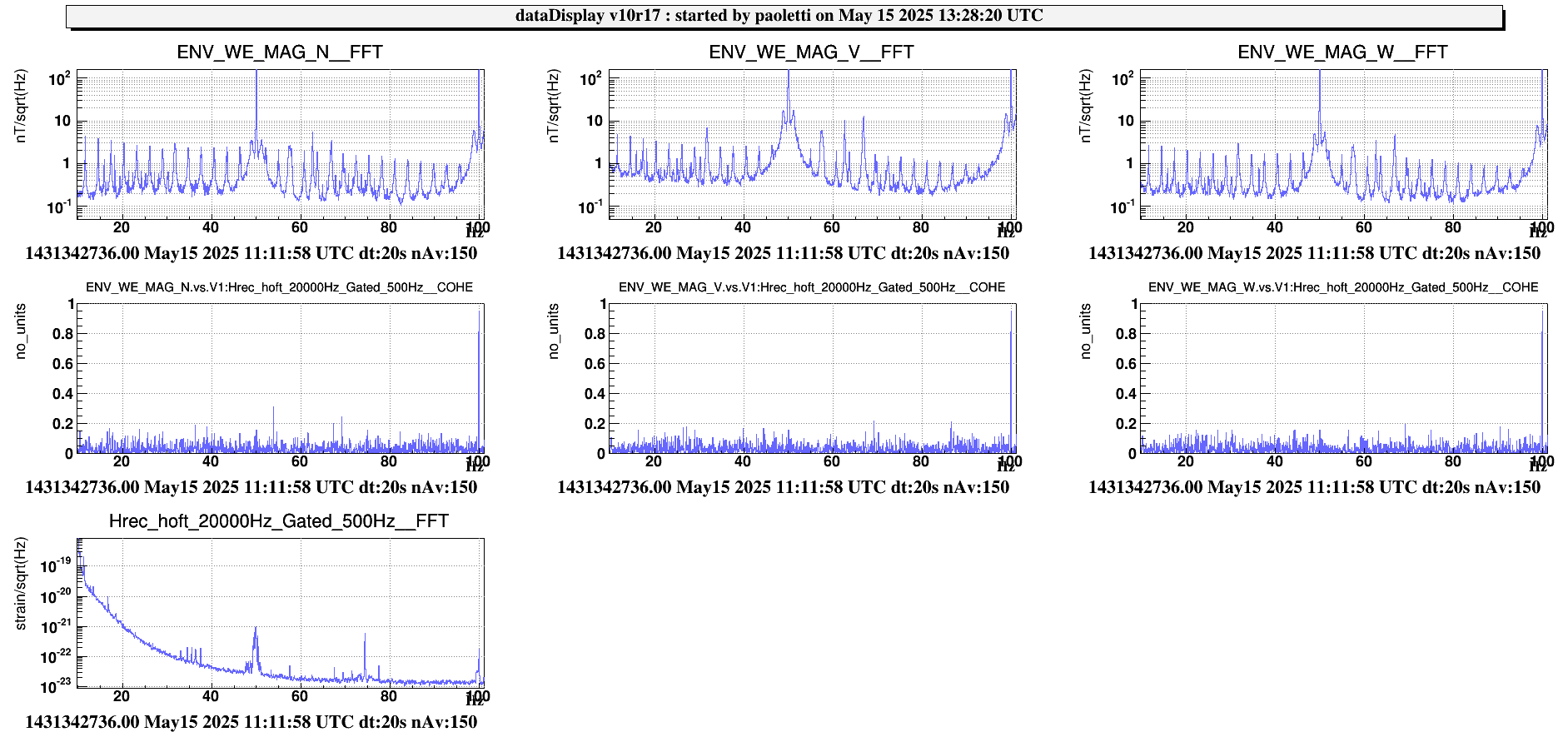
  • Figure 2: Comparison between RH off but connected (purple curve) and RH off and disconnected (blue curve).

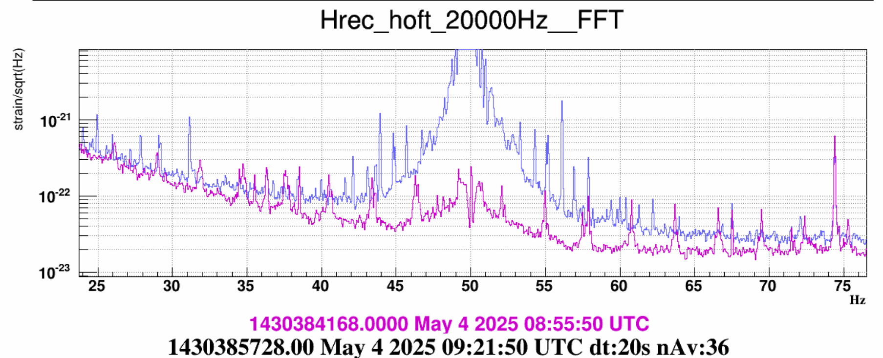
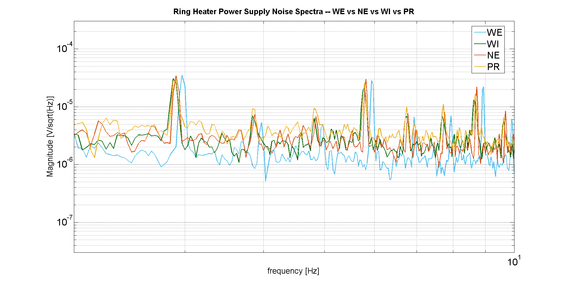
  • Figure 3: Zoomed-in view of Figure 2 for better detail. 

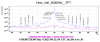
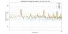
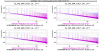
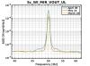
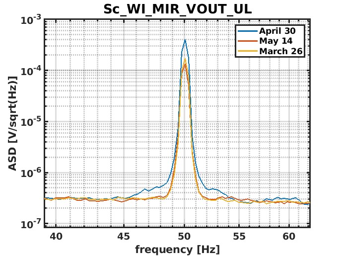
  • Figure 4: spectrum highlighting the 50 Hz sidebands.

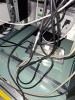
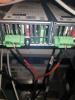
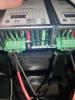
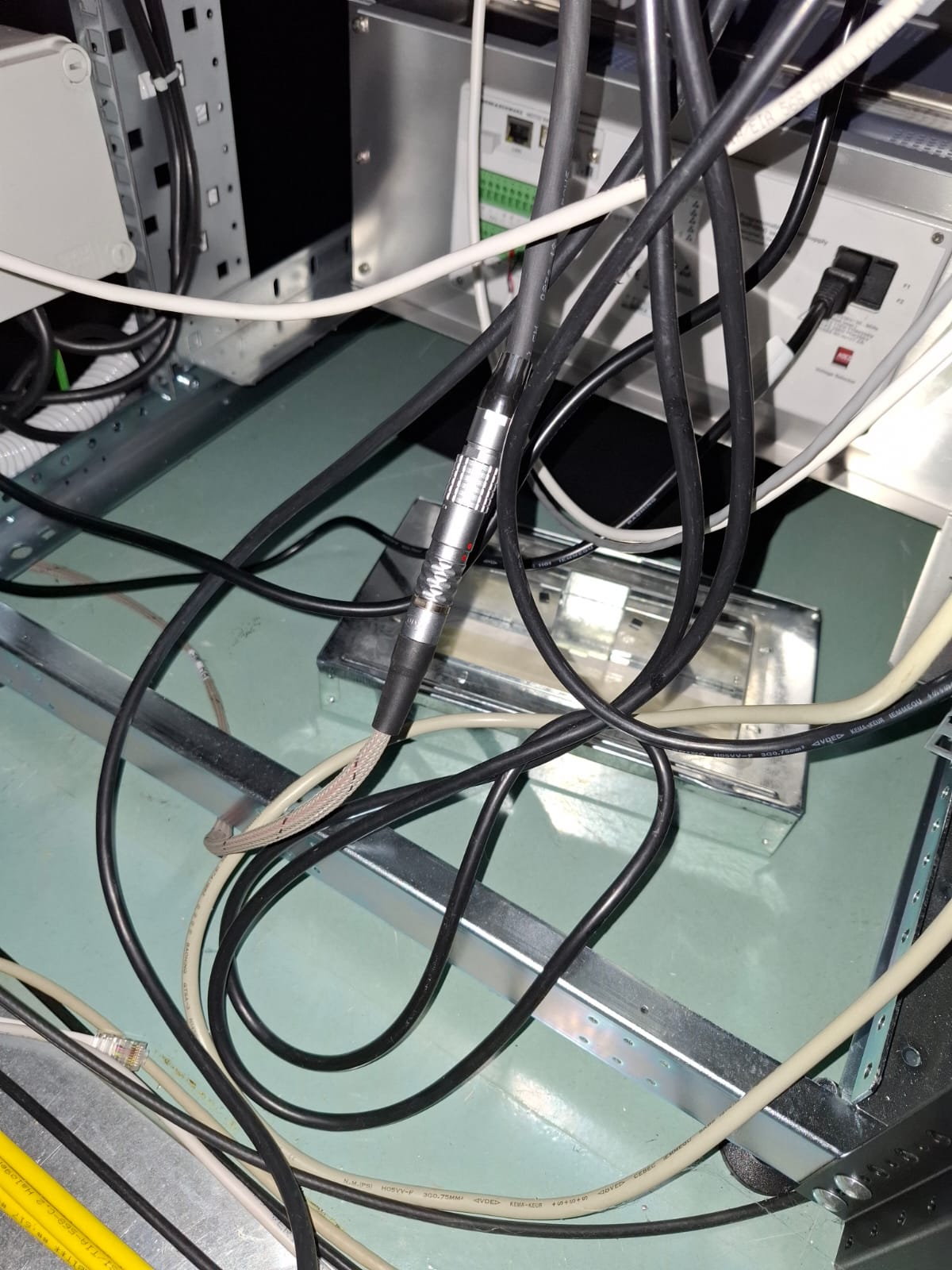
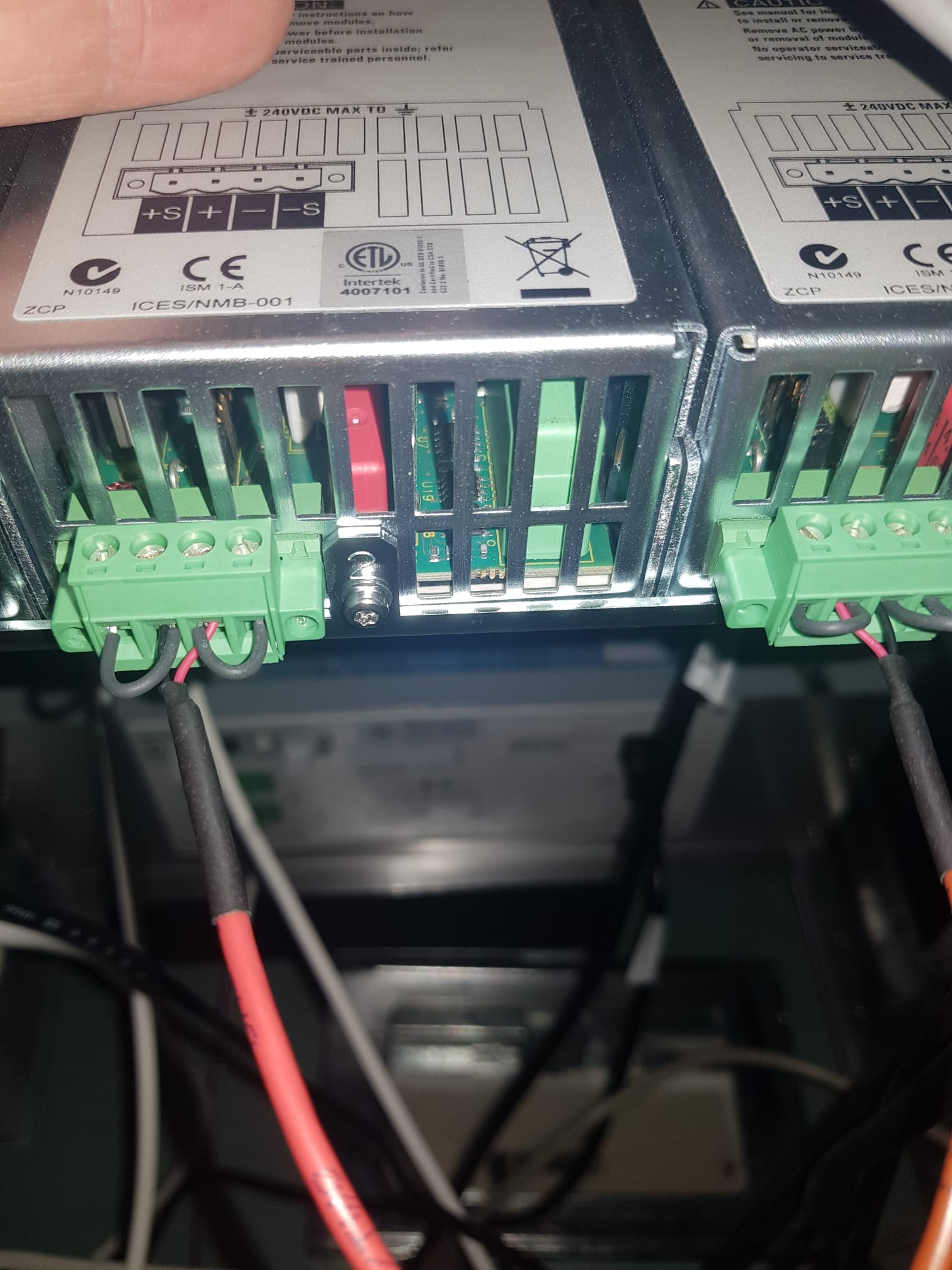
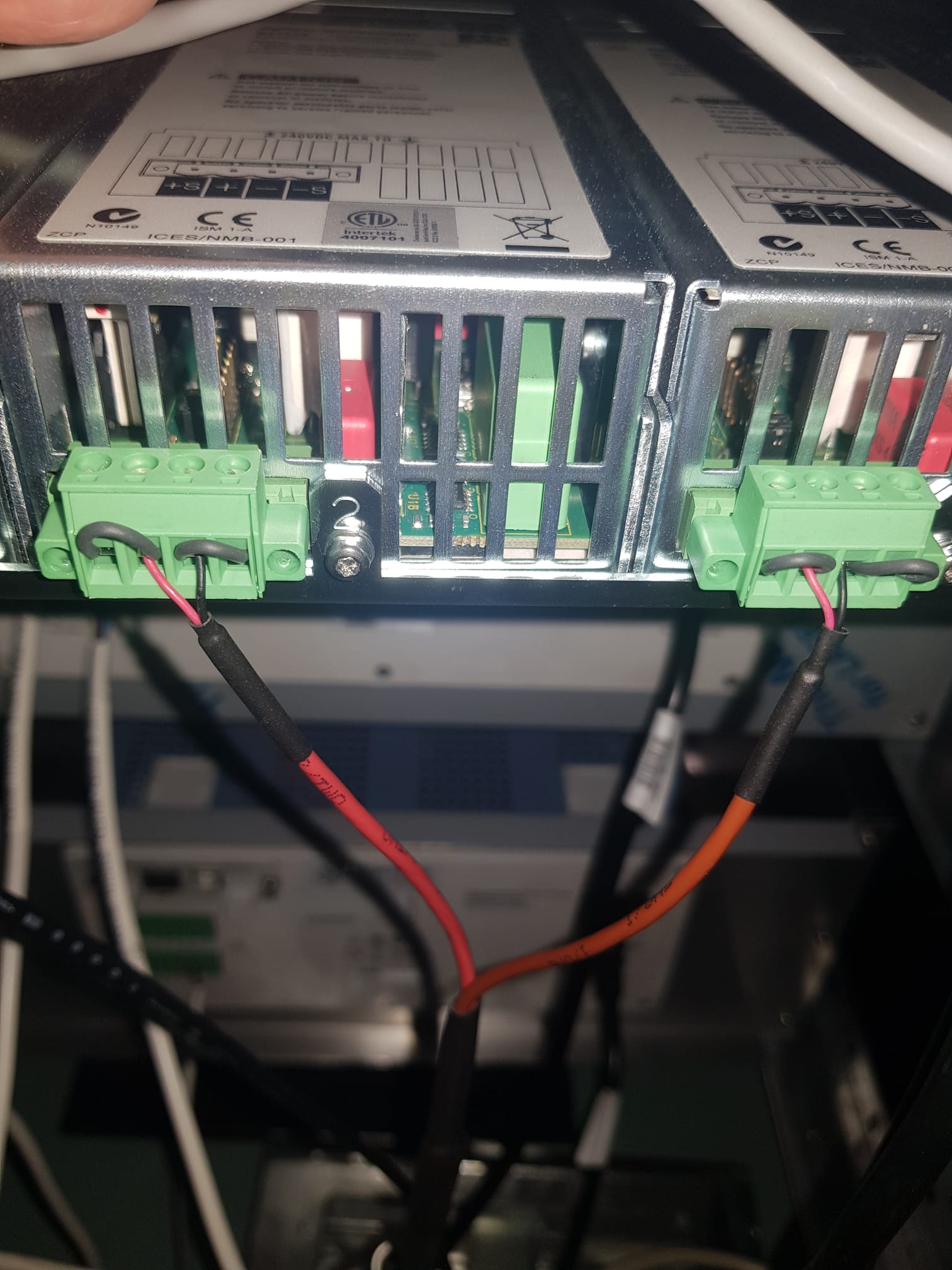
  • Figure 5: RH cable disconnected

After the unlock, Andrea reconnected the RH and left it in place. 

Side note: the WE RH was already disconnected during the investigation of the 25 min glitches (63246).
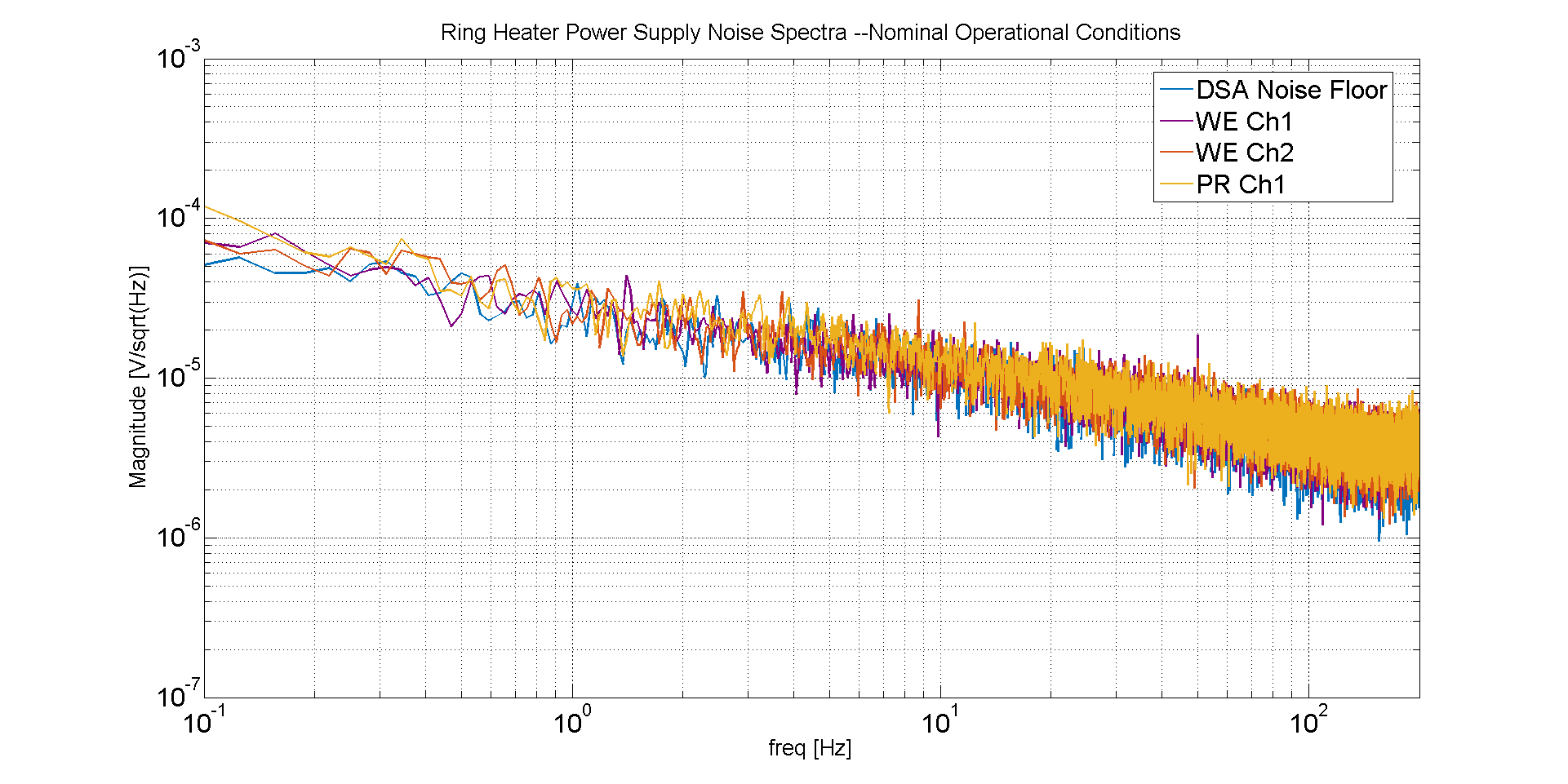
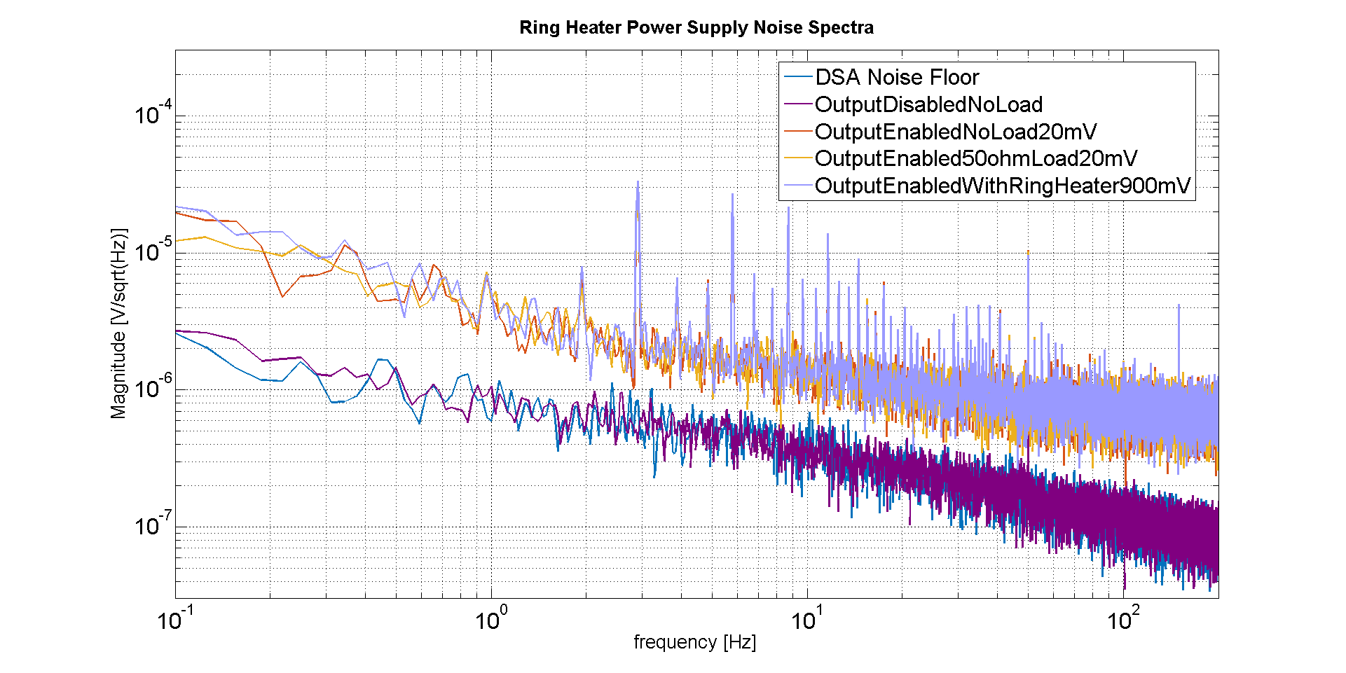
To be investigated: RH power supply and its cabling

Images attached to this report
Comments to this report:
nocera - 22:16 Monday 05 May 2025 (66716) Print this report

I. Fiori, B. Montanari, I. Nardecchia, F. Nocera, M. Tringali

I'll attach here two sets of spectra. The first one represents the data taken in nominal operational conditions (17.2 V, around 300 mA of current) of both channels of the West End Ring Heater Power Supply (Ch1 and Ch2) and of the reference one, the PR Ch1. As it can be seen there is neither significant difference among them nor with the measurement noise floor, the Dynamic Signal Analyzer's noise.

Since it has been reported that it was possible to see the 3 Hz comb spectra with the Power Supply on but *not* enabled (no current drawn), we measured the spectra again in this condition as well using the best possible DSA sensitivity. Here too no distinctive feature, only the 50 Hz line visible on both Power Supply channels.


Images attached to this comment
nocera - 8:01 Tuesday 06 May 2025 (66718) Print this report

I. Fiori, B. Montanari, I. Nardecchia, F. Nocera, M. Tringali

Today we kept investigating the 3 Hz comb and its relationship with the 3 WE Ring Heater electronics.
What we did was to compare WE Power Supply behavior with an equivalent one used for the same purpose elsewhere (PR). The data will be posted as a comment to this entry soon.

The takeaway message is that the output spectrum of the Ring Heater Power Supply used at the WE is comparable of the one used at the PR and that no evidence of the 3 Hz comb is visible in either case.
As said, plots will follow.


dattilo, gherardini - 17:40 Tuesday 06 May 2025 (66723) Print this report
This morning we carried out a check of the cabling connecting the Ring Heater. In summary, nothing abnormal was detected.

We checked both the cabling starting at the RH driver and on the vacuum flange. We saw that the impedance is the usual one (~60ohm at the RH driver level), and that the RH conductors are not in contact with the shield or with the ground. Furthermore, the shield is also floating with respect to the ground, as per the cable construction.
In the afternoon Fabio and Gianmatteo also verified that there is no accidental contact between the RH conductors and the conductors of any mirror coil.
nocera - 21:22 Tuesday 06 May 2025 (66724) Print this report

B. Montanari, I. Nardecchia, F. Nocera, G. Sposito

New chapter on the 3 Hz comb investigation.
The original idea was to repeat yesterday's measurements but with the real load connected instead of an equivalent one as previously done.
To understand our findings (and yesterday's lack of) it is essential to recognize there are 3 possible states for the Ring Heater Power Supply: (1) OFF (2) ON but with the output disabled (3) on and with the output enabled.

Plots will be provided in support of the conclusions reported here in a following entry.

The conclusions are:
(a) the 3 Hz comb feature is intrinsic to the Power Supply used, we tested the installed one with its two modules and a spare one with an additional module and they have all the same type of behavior
(b) the 3 Hz comb does not depend on the load; it is always there with and even without the load connected to the power supply in the conditions specified below
(c) it is *never* there when the Power Supply is OFF (duh) or when its output is disabled --conditions (1) and (2) mentioned above
(d) it is *always* there when the output is enabled no matter what the requested output voltage is, even if is 0 V and no current is actually supplied
(e) it therefore looks like it has always been there, but that its coupling to the Dark Fringe in the past used to be for some reason smaller then it is now
(f) the spare Power Supply has a slightly different, and worse, signature (additional and perhaps with larger magnitude frequency lines), but to make sure of that I need to analyze the data

to be continued

ilaria - 6:34 Wednesday 07 May 2025 (66727) Print this report

Many thanks to the Electronics and ENV teams for their help and support.

verkindt - 16:06 Wednesday 07 May 2025 (66732) Print this report

On the spectrogram shown in elog66702, there was a decrease (around 09h08) and an increase (around 09h15) of the 50 Hz line. Those changes had a few minutes of latency with respect to the connection or disconnection of the cable. As pointed out by Michal during the commissioning meeting, this was due to way the noise subtraction is done in Hrec. If we look at the channel Hrec_hoft_raw_20000Hz (before noise subtraction), this effect is not present anymore (upper spectrogram of plot1). We can see also on plot1 that the 150 Hz line decreases when the cable is connected and that the 100 Hz line increases when the cable is connected (between 09h03 and 09h11).

Images attached to this comment
ruggi - 18:09 Wednesday 07 May 2025 (66735) Print this report

An additional information, never reported in a log-entry, concerning a different ITF sensitivity to electrical stuff after WE intervention: the feed-forward used to remove the 50 Hz from the sensitivity did not work anymore and it required a relevant adjustment of the parameters, both in gain and in phase. Considering that the feed-forward uses as witness an electrical channel from the central area, and considering that the cancelation worked fine after the parameter adjustment, I assumed that WE building, tower or other WE devices  were not involved in the issue, but maybe my conclusion is wrong.

nocera - 16:52 Thursday 08 May 2025 (66741) Print this report

B. Montanari, I. Nardecchia, F. Nocera, G. Sposito

Overdue entry with plots justifying the conclusions listed in the entry 66724.

After a few days of discussion of this topic it looks like some people are still confused regarding the pieces of the puzzle. Here's a brief recap.

The Ring Heater system for a given tower (in our case, WE) consists of
- one Keysight N6700 Modular Power Supply, which in turn is made of
    • a single mainframe, or chassis
    • 2 separate N6752A 100W Power Modules, each one driving one Ring Heater
- cabling, both in air and, after the flange, in vacuum
- 2 Rings, driven with opposite polarities.


A block diagram is provided, I hope that helps.

And now the measurements.

Fig. 1 shows the measurement taken on May 6th at the WE using the spare mainframe and one of the two already installed Power Modules. It shows that when the output is disabled, there is no 3 Hz comb, while when it is enabled is always there and with the same magnitude no matter what the required voltage and current are

Fig. 2 compares measurements taken at WE with the ones taken at NE. It shows that different power supplies have slightly different combs (frequency is not exactly the same) while comb magnitude does not change.

Fig.3 displays side by side 4 different power supplies (WE, NE, PR, WI) further confirming each has its own signature comb, as it is easily visible in Fig.4. a zoomed-in version of Fig. 3

Finally, a couple of points are addressed by the last two plots.
Fig. 5 shows that the comb is a characteristic of each power supply and is not influenced at all by where the power supply is located; the spectra for the spare one as measured at WE and in the Electronics Lab are the same.

Fig. 6 instead shows that the comb is a feature of the mainframe and not of the power modules it hosts (Ch1 and Ch2 are equal)

Images attached to this comment
Non-image files attached to this comment
dattilo, gherardini, montanari, sposito - 13:02 Friday 09 May 2025 (66744) Print this report
Here is a summary of the tests performed yesterday (Thursday 8th):

- verification of the impedances of the mirror and marionette coils, of their isolation towards the tower. We have seen that the impedance is the usual one and that the coil conductors are not in contact with the screen or with the ground. The measurement was performed at the level of the feedtrhoughs on the flange. In the case of the mirror coils it was also performed at the level of the relay box.
From an impedance and insulation point of view, no anomalies were found. In particular, the DR coil mentioned by Michal in his entry https://logbook.virgo-gw.eu/virgo/?r=66736, it appears that from an electrical point of view it is the same as the others.

- RH driver common mode voltage measurement. ( Such an anomaly, if present, could have an electrostatic effect on the mirror). We performed the measurement with the driver connected to the RH, with a supply voltage of 200mV, measuring the voltage between a conductor of the RH (near the driver) and towards the common of the driver and then towards the tower. The measurement was performed on both RH modules of the WE, and then for comparison on both WI modules. The measurement result was always the same: the comb at 3 Hz is visible in all cases, and with similar amplitudes, there are no asymmetries on any driver module. In the attached plot there is the comparison of the spectrum at WE and WI
Images attached to this comment
Paoletti, Dattilo, Sposito - 16:26 Friday 09 May 2025 (66745) Print this report

Today we tried injecting a signal on WE Ring-Heater, reading the signal on the mirror coils (SC_WE_MIR_VOUT).
This is a very relative test: it may give us indications of some asymmetry in the four coils, following the analysis made by Michal in entry #66736.

To perform this test, we used a balanced BF generator isolated from ground, so that it mimicked fairly well the behavior of the power supplies used to power the RH.

As a test signal we generated a 3 Hz square wave, with an amplitude of 1Vrms (and then 5 Vrms), but since the RH is a non-standard load (30 Ohm), the reading on the generator display is relative.


At first we sent the signal by leaving the connections of the two RH windings as we found them, and we were able to see the signal in the voltage monitors of the four coils, more or less equal between them.

Then we changed the relative phase of the connection of one of the two RH windings, and the signal in the monitor coils decreased in the frequency range between 0 and 100 Hz, while remaining fairly equal after 100 Hz.

At the end of the tests, we reconnected everything as at the beginning.


Preliminary conclusion:

1) we did not notice any obvious differences in the signal seen by the four coils under any condition of the test.

2)  It is likely that, although care was taken at the beginning of the installation of the RH (years ago) to respect a certain phase necessary for noise reduction, some unintentional inversions occurred during the last interventions on the WE mirror (to be verified).

3) it seems the reduction of the noise is effective only up to 100 Hz , maybe for some "capacitive" asimmetries (just a guess) - we stress again on this relative measurement: the good one will be having again the ITF locked, and looking at Hrec.

It is worth noting that on the air side it is very easy to put things back in place with the good phase, because you only need to reverse the connection of one of the two windings on the power supply connector.
 

Now, at the first ITF relock, we should see the 3 Hz comb again; then reversing one of the two connections should reduce it.

Once the sensitivity of the ITF has been recovered, it would be worthwhile to do a new test of injecting a known signal into the RH while the ITF is locked, so as to understand the real coupling with Hrec.


Logfile is attached


Images attached to this comment
Non-image files attached to this comment
majorana - 4:42 Sunday 11 May 2025 (66746) Print this report
Is the “the better” situation the same also for the other RHs on TM? It seems worthwhile to check. Also, could the presence of these lines be avoided at the source?
Paoletti - 12:52 Sunday 11 May 2025 (66747) Print this report

1) I would say it is the “best” at least as far as NE's RH is concerned, otherwise we would have already had the same problem (we know that all power supplies of that kind create that interference). Maybe the same rationale can be applied to PR.
Other RHs should be “disabled” by default (if I am not mistaken), so they have no noise coming from the power supply.

2) Another power supply could be found that doesn't have that “comb”, but don't forget that the level of the comb is just above the level of the noise floor of the power supply itself, so you have to be careful to find a power supply that is also quiet enough.
Or you design a new one from scratch

fiori, tringali, paoletti - 17:02 Wednesday 14 May 2025 (66777) Print this report

In today's lock the 3Hz comb and the broadband noise underneath seem no more present. Also the 178Hz peak is (at least reduced).

Images attached to this comment
Search Help
×

Warning

Error

The present report has been modified outside this window. Please check for its integrity in the main page.

Refreshing this page will move this report into drafts.

×