Reports 1-1 of 1 Clear search Modify search
AdV-PAY (NE and WE Payloads)
melo, bersanetti, casanueva, nardecchia - 17:25 Friday 02 May 2025 (66696) Print this report
WE point absorber imaging

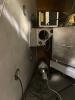
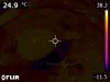
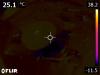
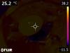
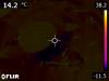
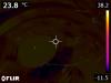
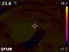
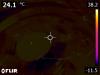
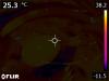
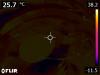
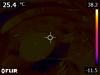
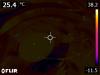
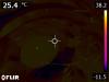
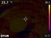
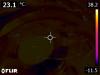
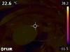
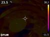
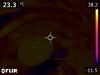
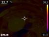
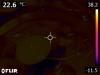
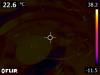
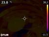
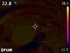
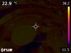
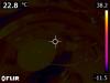
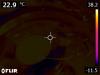
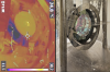
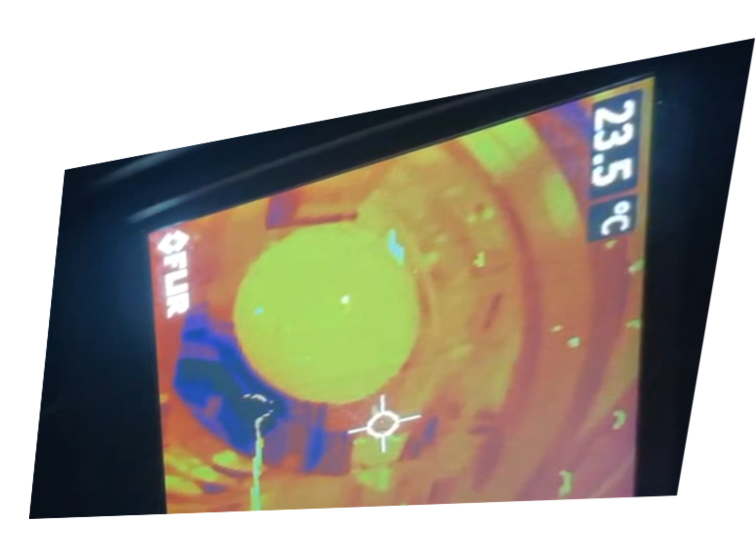
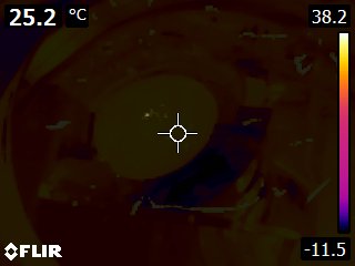
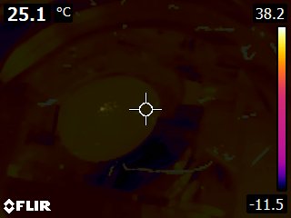
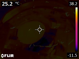
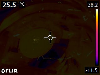
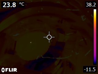
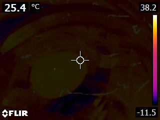
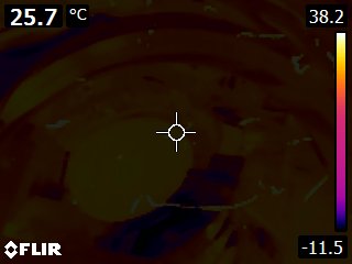
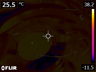
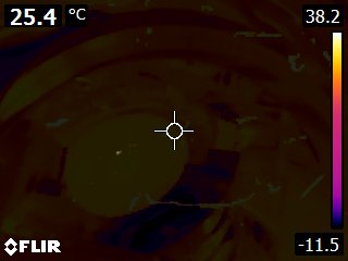
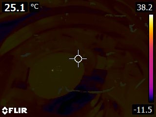
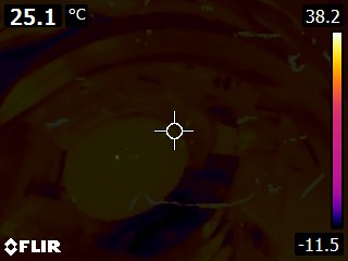
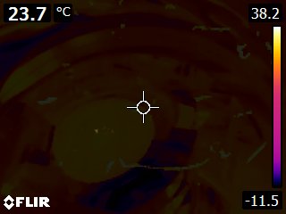
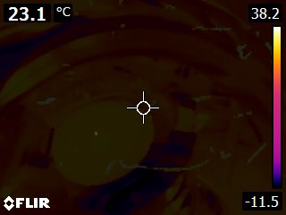
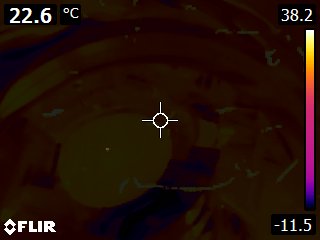
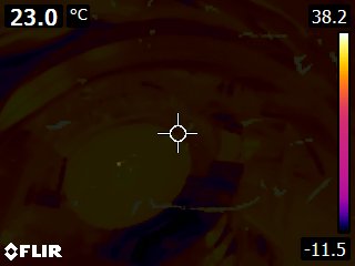
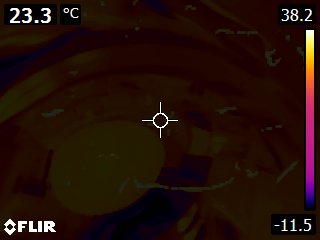
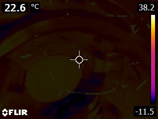
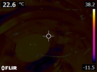
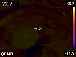
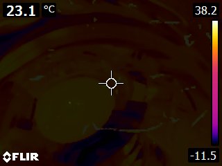
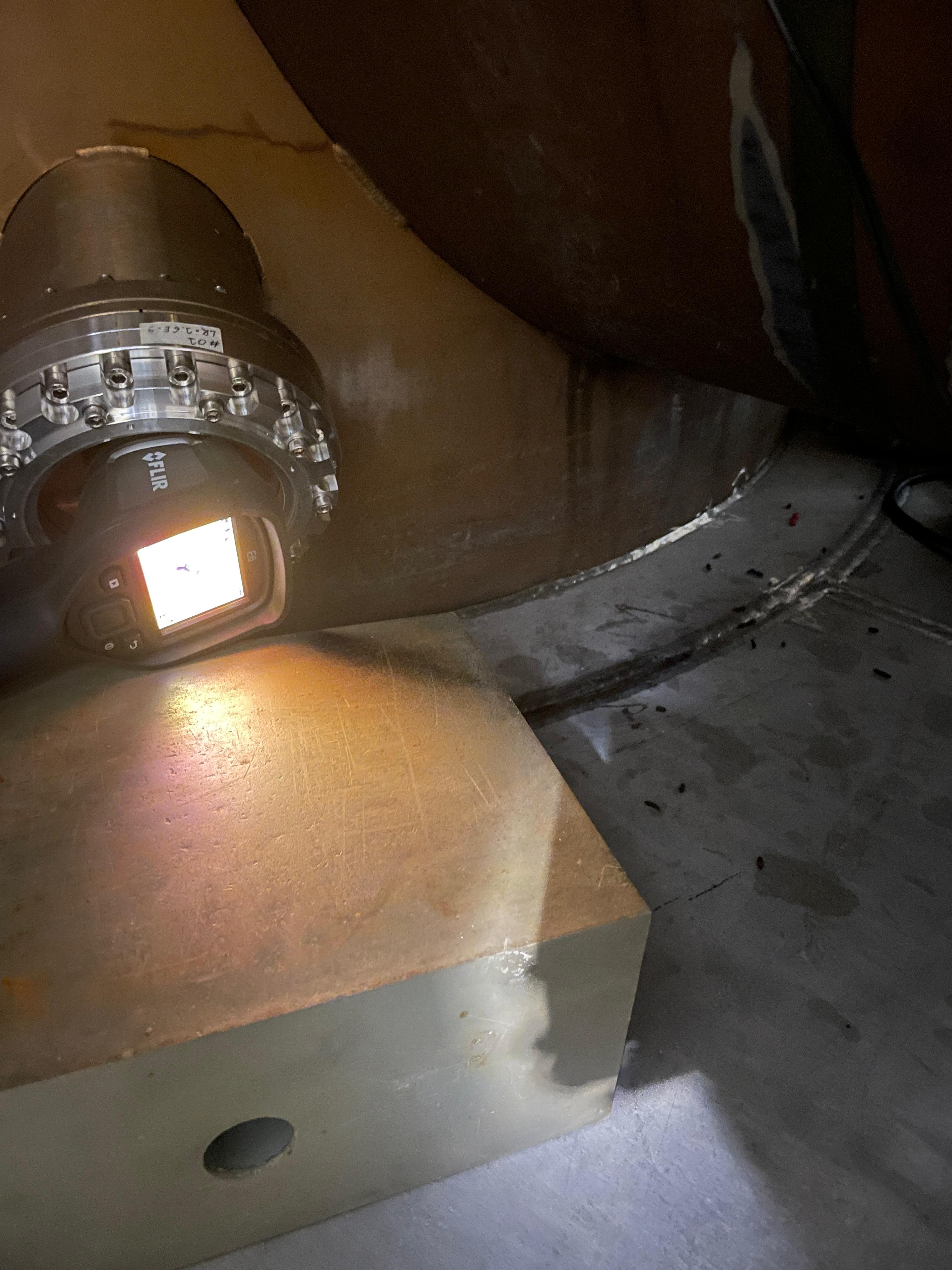
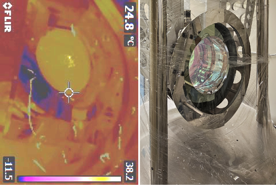
On Wednesday afternoon I went to WE building in order to do some measurements of the HR surface of the WE payload with the thermocamera (FLIR E6) to investigate the point absorbers issue (Thanks to M. Tringali for the support finding the viewport and setting the spot for the thermocamera).

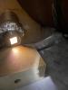
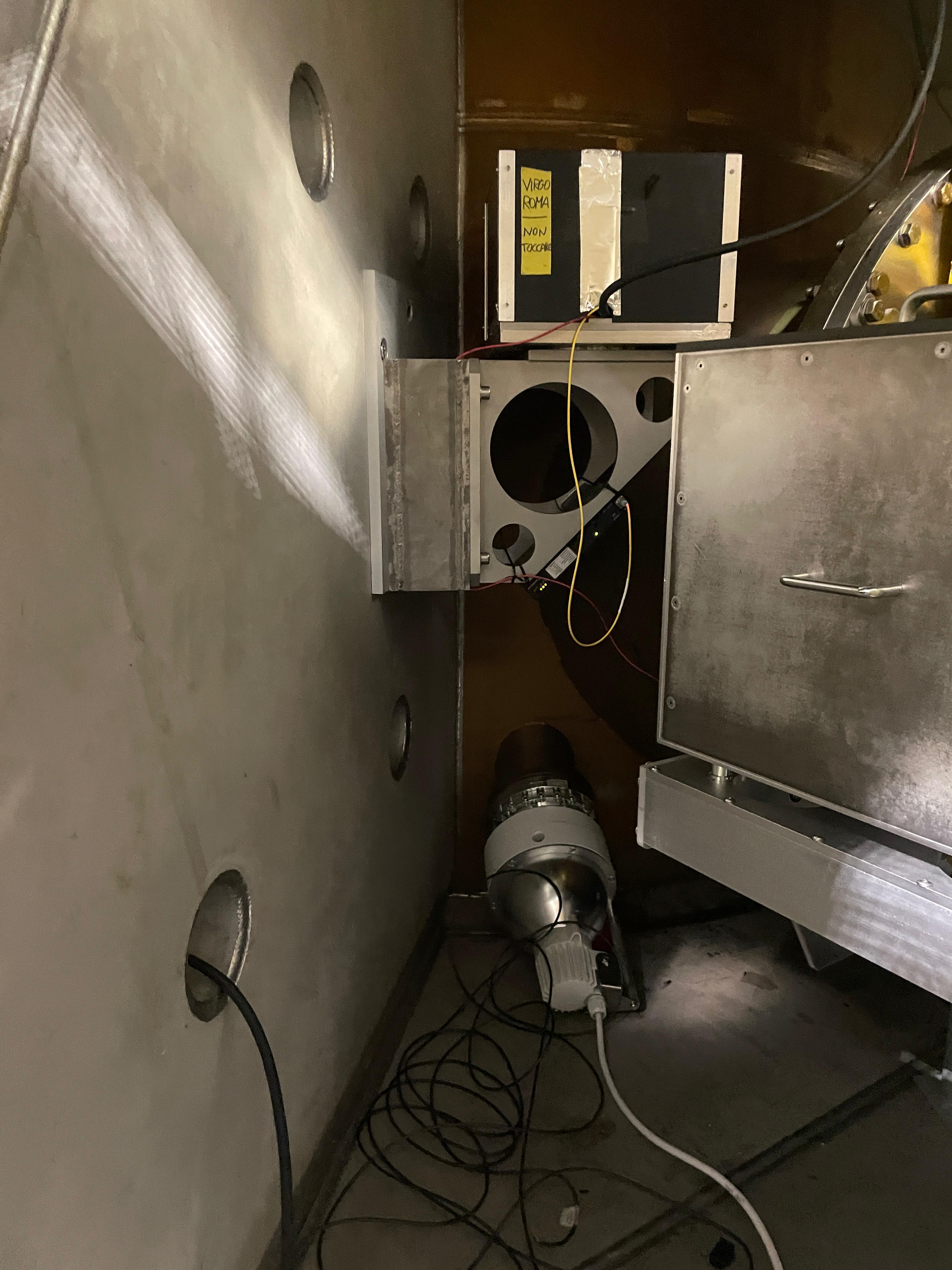
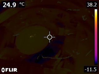
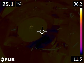
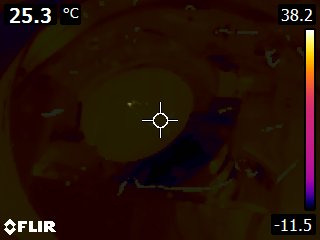
Upon arrival (around 16h local time) the ITF was locked, but while accessing the ZnSe viewpot (see Fig. 1, 2) the ITF unlocked. I waited until the ITF was locked again (in CARM NULL) and took several images with the thermocamera. 

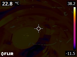
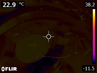
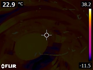
The idea was to take some images in CARM NULL and afterwards apply an offset of + 6 um of WE_Y_SET and take some more images to compare both configurations. However, after 30 min roughly that the ISC team changed offset with a ramp and the ITF was arriving in steady-state, it unlocked. Unfortunately, when the ITF was almost locked again, the battery of the thermocamera discharged (around 18h) and I could not go on with the measurements. 

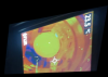
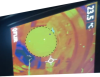
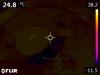
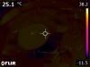
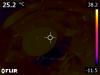
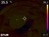
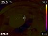
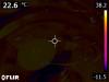
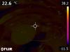
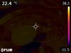
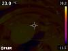
For now, I'm attaching some videos of the beam reaching the WE payload in CARM NULL configuration without offset (Videos 1 and 2). Video 3 instead was recorded while the offset was being applied with a ramp, therefore during the transient. 

Soon I will add more details to this entry and attach the images of the thermocamera. 

Images attached to this report
Non-image files attached to this report
Comments to this report:
mwas - 10:00 Monday 05 May 2025 (66708) Print this report

One can try to estimate the position of the point absorber on the mirror from these images.

Figure 1 shows the still from Video2, after deforming it using the "Perspective" tool of gimp to make the mirror look more or less as a circle.

Figure 2 shows the same as figure 2 with a circle overlaid to check that the rough perspective correction works.

The mirror diameter is 35cm, the edges of it are hidden by the baffle. I am not quite sure what is the inner apperture of the suspensed baffle, I will assume it is 33cm in the calculation below. I am assuming the video is taken with the down direction the same as down in real life (direction of gravity atraction).

Using the "Measure" tool of gimp I find the following distances from the point absorber to the edges of the baffle.

75 pixels right
111 pixels left
73 pixels top
105 pixels bottom

which would mean that compared to the center of the mirror the point absorber is 3cm to the right, and 3cm to the top. The error bars on that estimation are at least +/-1cm. It would be good if someone else could repeat the same type of analysis to check if they arrive at a similar conclusion, the result may be depending on how exactly the perspective is compensated for. It may work better with the images directly capture by the thermal camera, which will not have the additional perspective of the phone looking at the thermal camera display.


Images attached to this comment
melo - 10:49 Monday 05 May 2025 (66712) Print this report

Here the images of the thermocamera:

- Figs. 1 to 12: CARM NULL (no offset)

- Figs. 13 to 65: Offset of +6um applied to WE_Y_SET (images of the transient)

- Fig. 66: Unlocked

Images attached to this comment
majorana - 7:07 Tuesday 06 May 2025 (66717) Print this report
In these pics is the vertical axis is oriented upwards or downwards ?
Is the view sight taken from view port SIDE_E CORNER_S HEIGHT_DOWN ?
melo, cagnoli - 14:13 Tuesday 06 May 2025 (66722) Print this report

The images were taken from the viewport indicated in the Fig. 1 (LogE 66696), which is the ZnSe viewport located at the east side bottom of the HR surface of the WE mirror. The images were taken with the thermocamera rotated 90 degress clockwise (see Fig. 2). This means that the images posted in LogE 66712 should be rotated 90 degress as shown in Fig. 3. Be aware that in the left picture we see the mirror from below, whereas in the right picture we see the mirror from above. In both pictures the view is from the left side of the mirror.

Moreover, the images were done using the thermal blending mode of the thermocamera, which means that the camera displays a blended image that uses a mix of infrared pixels and digital photo pixels.

Images attached to this comment
Search Help
×

Warning

Error

The present report has been modified outside this window. Please check for its integrity in the main page.

Refreshing this page will move this report into drafts.

×