From Tuesday April 15 to Thursday April 17, we worked in the detection lab to install an OMC cavity on the B1s beam. This new cavity has been installed on the External Detection Bench (EDB).
General layout:
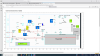
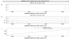
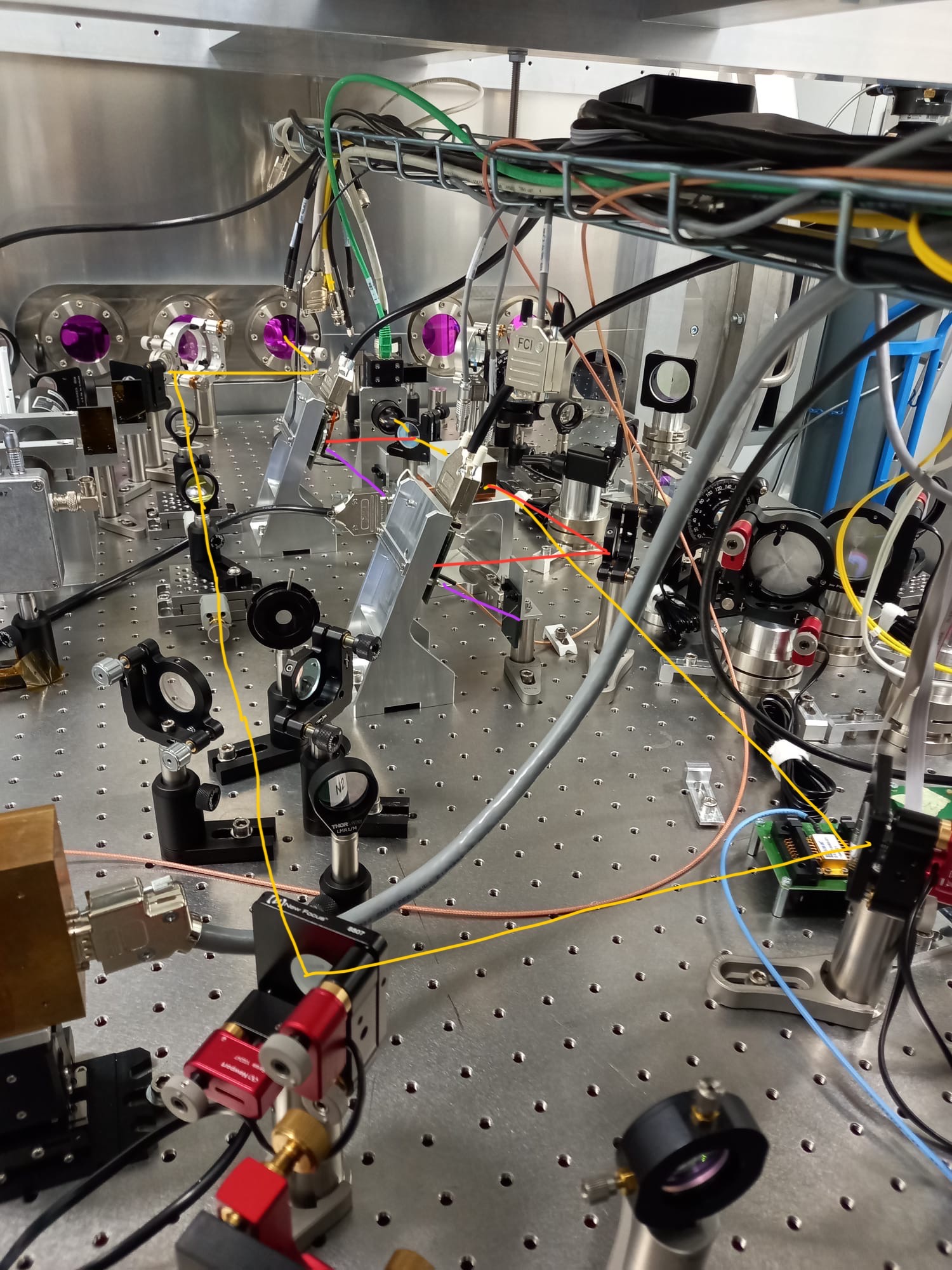
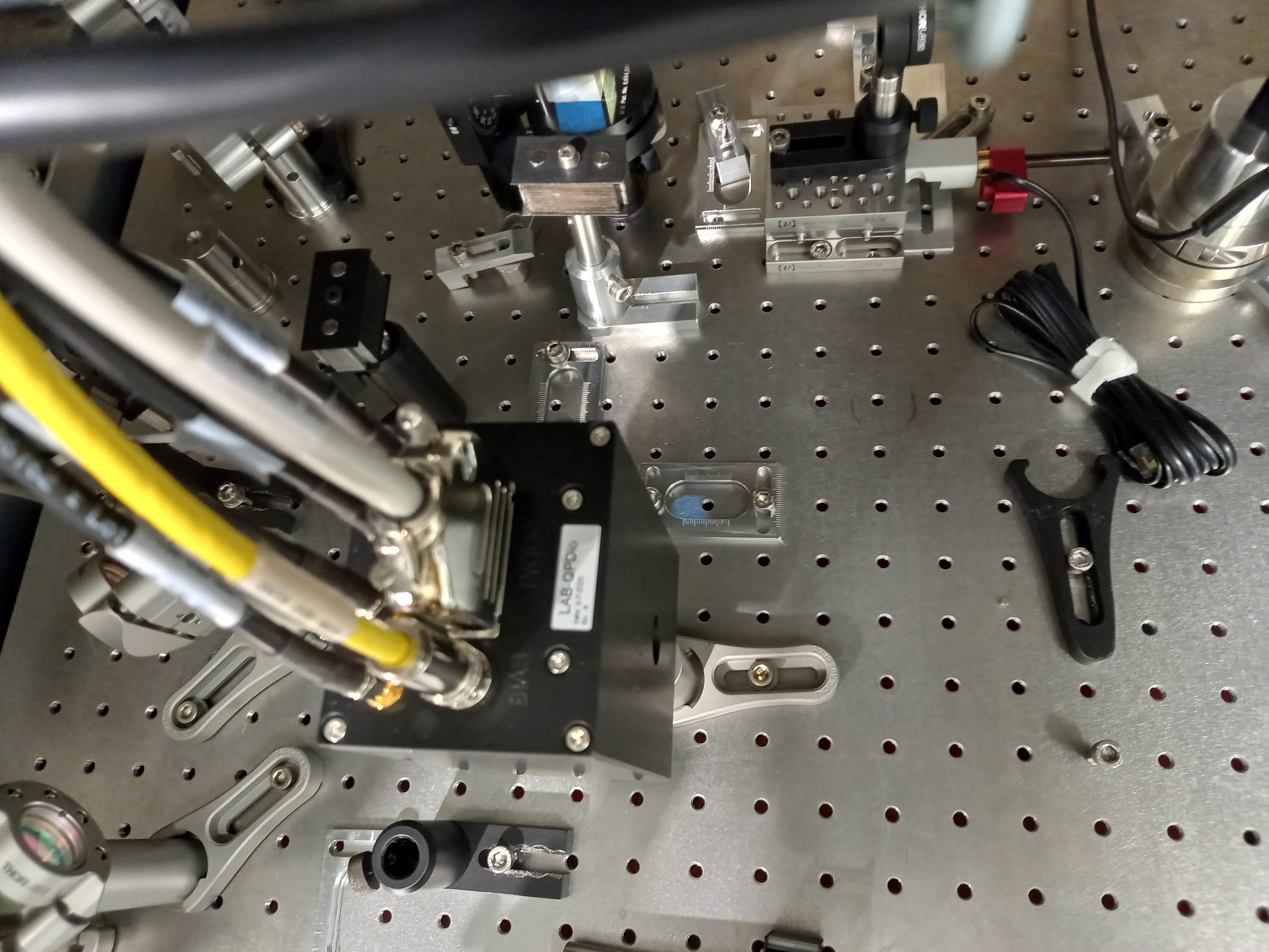
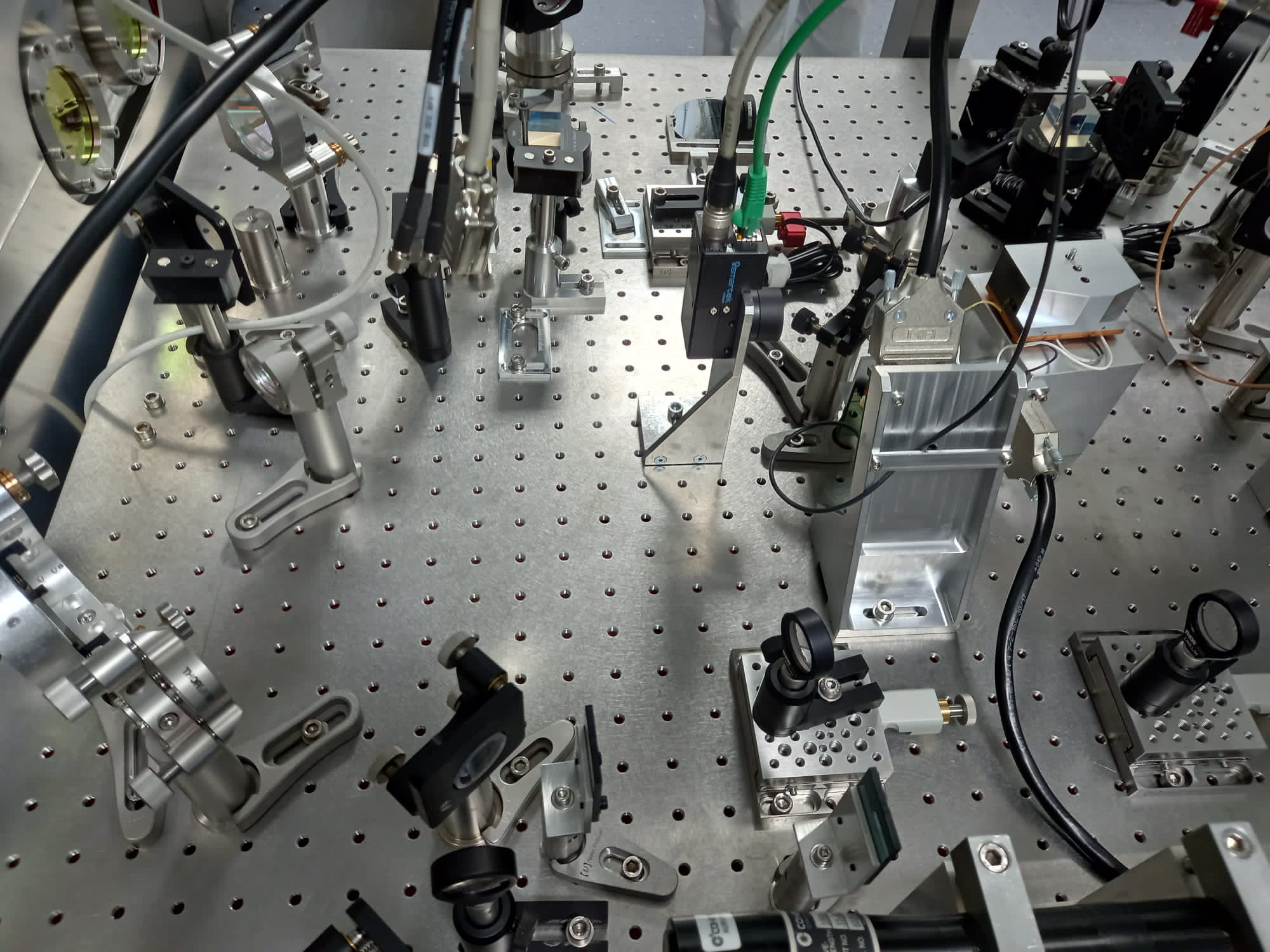
Fig.1 shows the Optocad layout of the OMC setup on the EDB bench that we intented to install. It gives the general idea, even if in practise we had to adjust the positions of the folding mirrors, the lenses and the OMC to comply with the mechanical constraints present on the bench and to adapt the mode matching telescope to the real parameters of the beam. The picture shown on Fig.2 shows how we really installed the new components. The path followed by the beam is shown in yellow and red.
First the B1s beam goes through 2 folding mirrors (EDB_B1s_M1 and B1s_M2) for which we re-used already existing mirrors. We only shifted the B1s_M2 mirror further south, placing it 17 cm souther than to the first mirror M1. Then the beam is going through a mode matching telescope made of two spherical lenses B1s_L1 and B1s_L2 (more details provided below) and then reaches two new folding mirrors (B1s_M3, and B1s_M4) that will be used for OMC alignment. The separation between M3 and M2 is 82.5 cm along the west-east axis. The distance between M4 and M3 is equal to 27 cm. The B1s_M4 mirror sends the beam towards the OMC cavity, whose input surface is about 47.5 cm from the M4 mirror. The beam reflected by the OMC is then sent towards a folding mirror that directs the beam towards the reflection photodiode. The beam transmitted by the OMC is sent towards a beam splitter highly reflective (R=0.99) which seperates the beam between the transmission photodiode and a camera.
Removal of existing QPD and galvo:
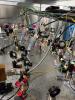
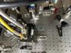
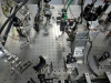
In order to implement these modifications, we had to make room in the central part of the bench by removing the RF quadrant shown on Fig.3 and the galvanometer mirror and the folding mirror shown on Fig.4. These elements were displaced towards the east side of the bench.
Installation of the new components on the bench:
The following components were added on the bench:
- The two lenses L1 and L2, mounted on manual translation stages ;
- We also installed two glass beam dumps to block the ghost beams reflected by these two lenses. One of this beam dump is also blocking the beam going towards the SFP.
- The mirrors M3 and M4, with motorized mounts (picomotors)
- The OMC SN3 (10% losses) on its support. The cover is partially anodized to make it absorbant. We have put some indium layers around the Peltier cells and between the copper support and the glass substrate. The PZT is wrapped inside kapton. The PZT srew was tightened with a torque of 0.20 cN.m.
- The photodiode in reflection of the OMC, mounted on the preamplifier SN220 (50 mW). Due to a problem with the connector, there is no shutter on this preamplifier.
- The photodiode in transmission of the OMC, mounted on the preamplifier SN221 (11 mW). This photodiode is equipped with a shutter.
- A folding mirror used to center the beam on the reflection photodiode.
- A folding mirror with partial transmission of ~1% used to the center the beam on the transmission photodiode.
- A camera placed in transmission of the previous splitter.
- We also installed a beam dump in reflection of each photodiode.
Installation of new electronics and cabling:
We have installed an OMC driver beneath the two existing DAQ boxes. Furthermore, we have placed small separators among the boxes that allow for better evacuation of the heat.
We have installed a picomotor driver to which we have plugged the four picomotor cables, two for M3 and the remaining two for M4. Each cable controlling the motion in TX or TY. We have tested the picomotors and they worked as expected.
Both of the new preamplifiers were cabled to the DAQ box SN52 and SN113 following the foreseen cabling scheme: https://logbook.virgo-gw.eu/virgo/?r=66504
The OMC instrumentation (Peltier, PZT, thermistance) were also cabled following the foreseen scheme: https://logbook.virgo-gw.eu/virgo/?r=66504. The right part of the OMC driver is being used.
Mode matching telescope
The telescope is made of two spherical lenses (see Fig.5): the first lens is diverging with a negative focal length of -300 mm and the second lens is converging with a focal length of +300 mm.
The distance from the second surface of the first lens to the first surface of the second lens is ~15 cm. The surface convention of the lens is curved surface first then plano surface. We tilted the lenses in the horizontal direction in order to minimize the astigmatism effect on the waist.
Measurements to determine the position of the waist before the OMC
After installing all optical elements, we wanted to find out the waist of the beam before the OMC so as to locate its input surface. For this purpose, we moved the camera away from M4 and measured the size of the waist of the beam in the horizontal and vertical planes. This procedure was repeated multiple times by moving the camera even further. Initially we placed the camera at about 20cm from M4 and then displaced it by 5cm each time. Here are the measurements we did (x stands for the horizontal plane while y for the vertical one):
- reference point : wx= 362um wy=360um
- 5 cm from reference point: wx= 312um wy=355um
- 10cm from reference point : wx= 275um wy=354um
- 15cm from reference point : wx= 257um wy=352um
- 20cm from reference point : wx= 258um wy=350um
- 25cm from reference point : wx= 266um wy=368um
- 30cm from reference point : wx= 300um wy=396um
- 35cm from reference point : wx= 346um wy=435um
From these measurements we could conclude that the waist in both directions was between 15 to 20cm from the reference point (thus 35 to 40 cm from M4). Nevertheless, we notice astigmatism.
Following these measurements, we still changed a bit the tilt of the lenses in order to try to improve the mode matching with the OMC, but we did not take the latest measurements after this tuning. The best position for the OMC was found to be about 47.5 cm after the M4 mirror.
Alignment of the OMC
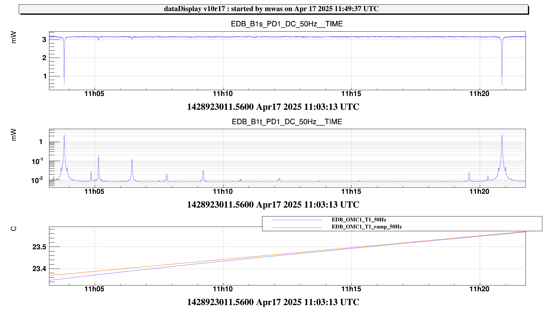
The OMC has been successfully aligned, reaching a power of about 2.5 mW on the photodiode in transmission and below 0.5 mW on the photodiode in reflection.
A scan of the OMC performed after this alignment is shown on Fig.6. The first order mode peak is about 10% of the TEM00, and the second order mode is about 5% of the TEM00.
Noise investigation with acoustic and taping tests
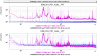
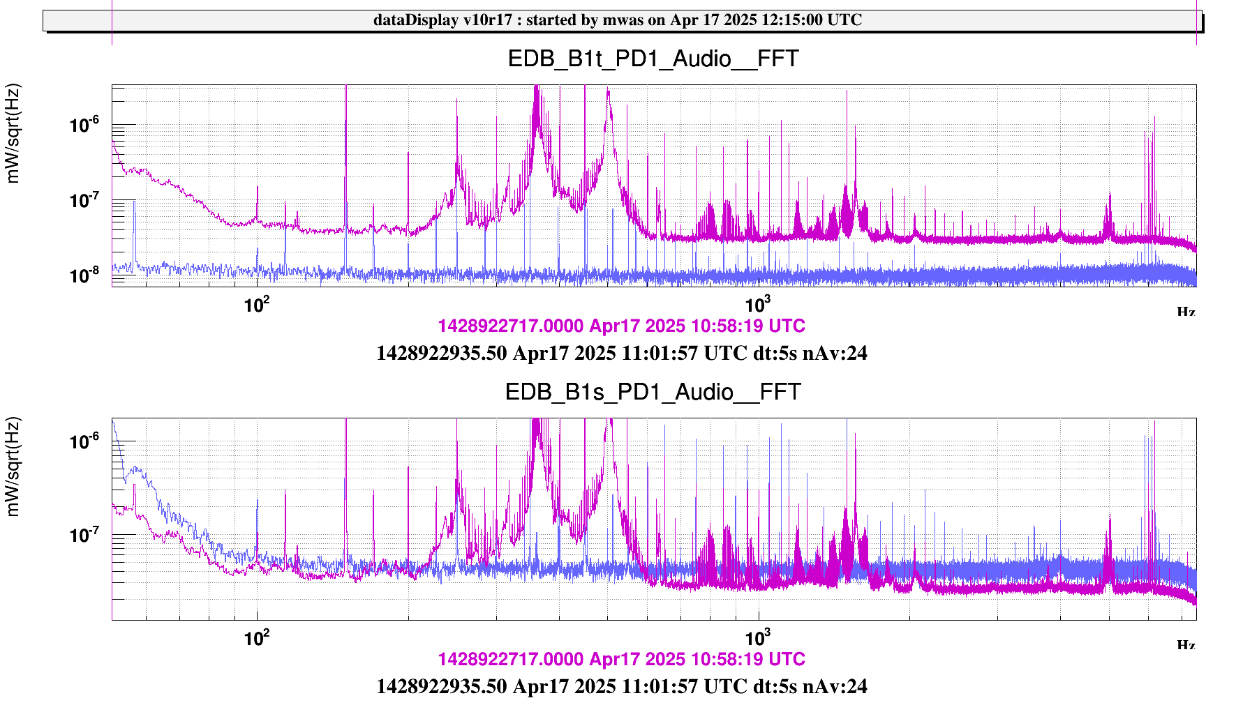
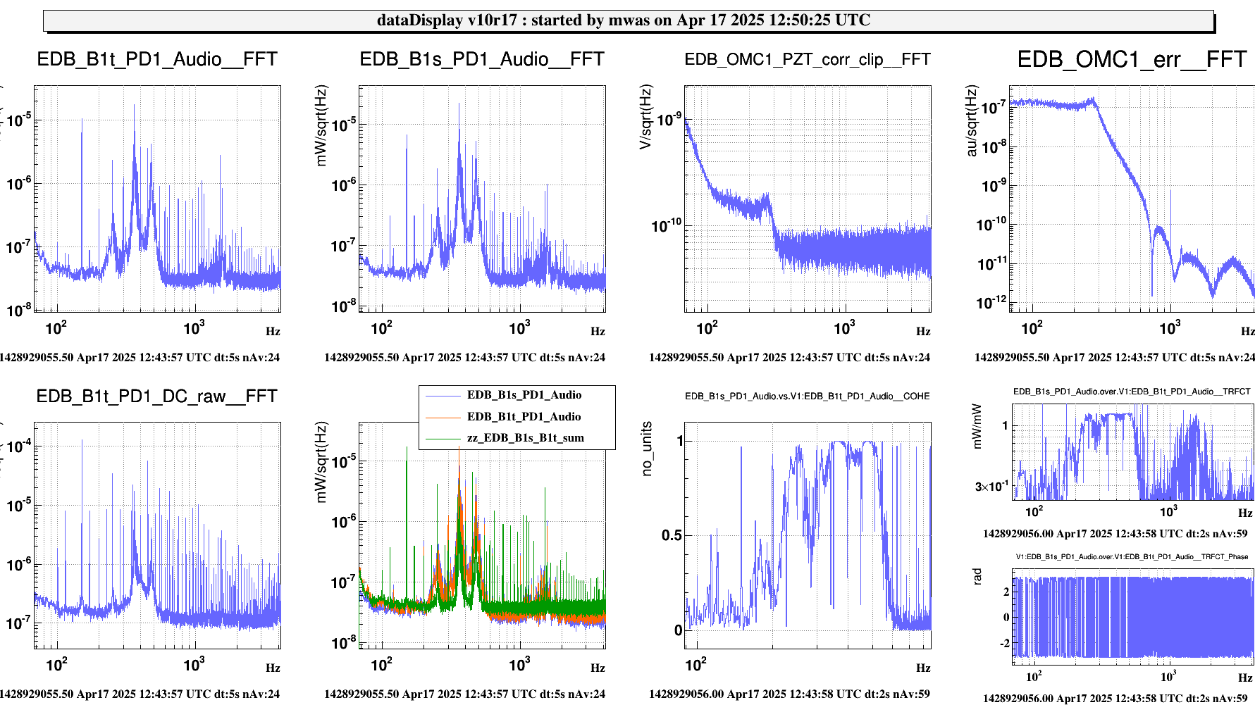
After having achieved a good mode-matching in our setup, we noticed that the audio channels associated to the PDs in reflection and transmission show an increase in noise when the OMC is locked. Figure 7 shows these two channels. We took a reference (blue curve) when the OMC is out of resonance and then when it’s in resonance (purple curve). When the OMC is out of resonance, the noise floor on the B1s PD is shot noise limited, while the noise floor on the B1t PD is at the level of the dark noise. When the OMC is in resonance, the noise floor on the B1t PD becomes limited by the shot noise. However we observe some excess noise, in particular in the frequency range between 200 and 600 Hz, where we observe several structures that look like mechanical resonances.
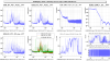
In Figure 8, we can see that this noise structures are coherent between the B1t and B1s photodiodes, and the power fluctuations between the two photodiodes are in opposition. This indicates that the excess noise is not due to clipping. Instead it behaves as a length noise of a beam jitter noise. We made the test of misaligning the OMC, and we observed that the coupling of the noise was increase, which argue in favour of beam jitter noise.
In order to investigate further the origin of the noise, we performed some acoustic and taping tests. Making noise near the bench was exciting the noise further. Tapping on any mounts on the bench or on any optics was exciting some resonances. Sometimes the same as the ones present without tapping, sometimes at different frequencies.
The bump at ~500Hz may be related to B1s M3. We have tightened the lateral screw on B1s_M3, this did not have much effect on the height of the peak. ~30 minutes after tightening we have noticed that the peak has moved slightly to higher frequency by ~20Hz. It might be related to the tightening of the screw, or to something else we did in the meantime.
We have also screwed into the bench several beamdumps around the HWS that were just attached magnetically. And removed several screws that were not screwed in, and several beam dumps that were not screwed in, and did not look like they block any beam.
