- We started by measuring the injection bandwidth of the SL : 0.99MHz. We optimized the injection of the ML and the injection bandwidth increased to 1.05MHz.
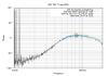
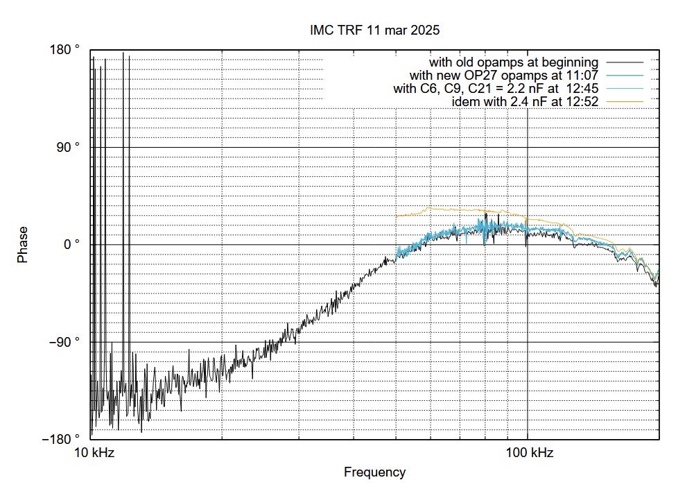
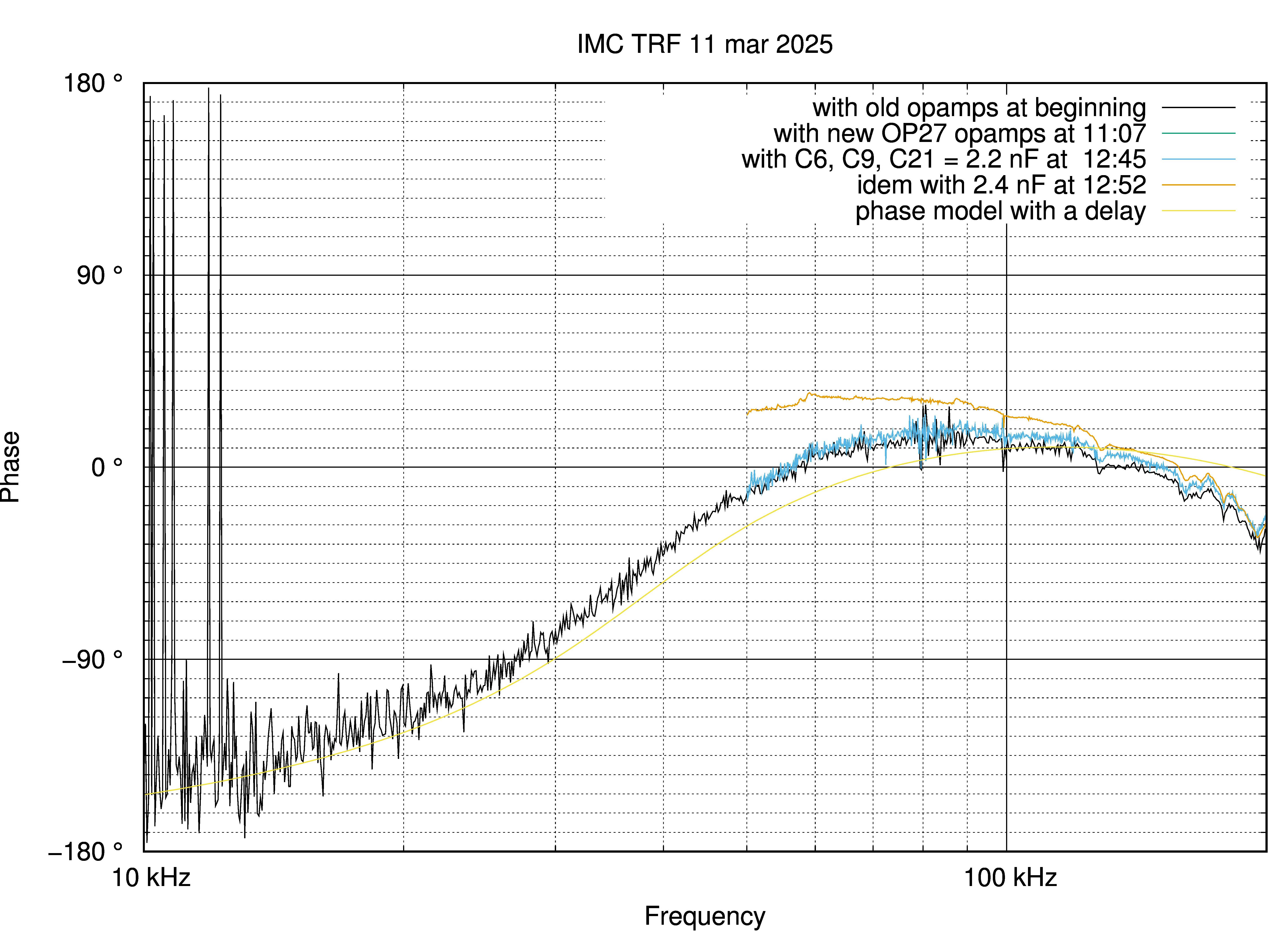
- The IMC OLTF was measured (black curve on fig1 and fig2) loop gain. The UGF is around 100kHz for a phase margin of 10°.
- The 4 Opamps op27 used for the 1/f^4 function were swapped with new ones (green curves) which increased the phase margin to 18°.
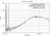
- The power injected into the SL was increased by 10% and the gain of the SL and PMC loops were reduced in order to avoid loop oscillation. No improvement were observed (blue curve) showing that the phase margin is not limited by the SL injection band. This is confirmed by the fact that the phase margin in the 1/f regime is of 45°. The 1/f^4 is expected to reduce the phase margin by 22° which is lower that what is observed.
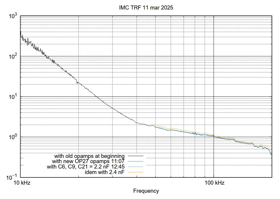
- The 1/f^4 corner frequency was reduced from to 33kHz to 22kHz by replacing the 3 capacitors (2.2nF up 3.3nF). The phase margin increased to 25° for an UGF of 100kHz. The gain was then increased so to have the UGF = 115kHz and a phase margin of 20° (orange curve, replace 24nF by 33nF in the caption)
The reduction of the corner frequency to 22 kHz reduces the gain at lower frequency by a factor 5 which explains the reduction of the sensitivity above 4 kHz (roughly a factor 2 at 10 kHz limited) . 2 intermediate values for the capacitors (2.4 nF and 2.8 nF) corresponding respectively to 30kHz and 26kHz.
The reduction in the ankle frequency between the 1/f^4 part of the loop and the 1/f part of the loop from 33kHz to 22kHz does not reduce the gain below 10kHz by a factor 5 but by a factor 3. This is the gain reduction is (33kHz/22kHz)^3, the exponent is 3 and 4 because the slope changes from 1/f^4 to 1/f above the ankle (and not from 1/f^4 to a constant).
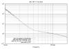
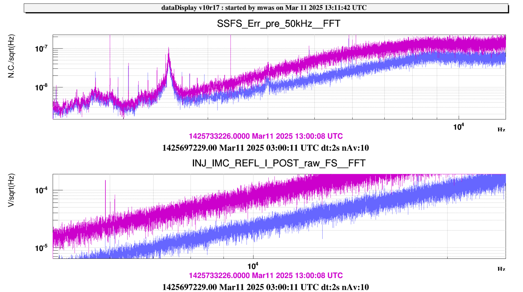
Figure 1 shows that we see the factor ~3.3 increase in the frequency noise seen on the SSFS and on the IMC reflection due to the reduction of the IMC loop gain below 10kHz. Below 3kHz there is no increase in noise as the SSFS loop has sufficient gain to bring the frequency noise at the output of the IMC below the sensing noise of the SSFS, hence below 3kHz the SSFS sensing noise still dominates the laser frequency noise.
