This morning we went in Laser Lab atrium to repeat the test of adding the electronics box that was used to inject the phase noise to the fibered EOM.
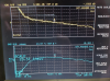
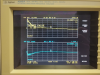
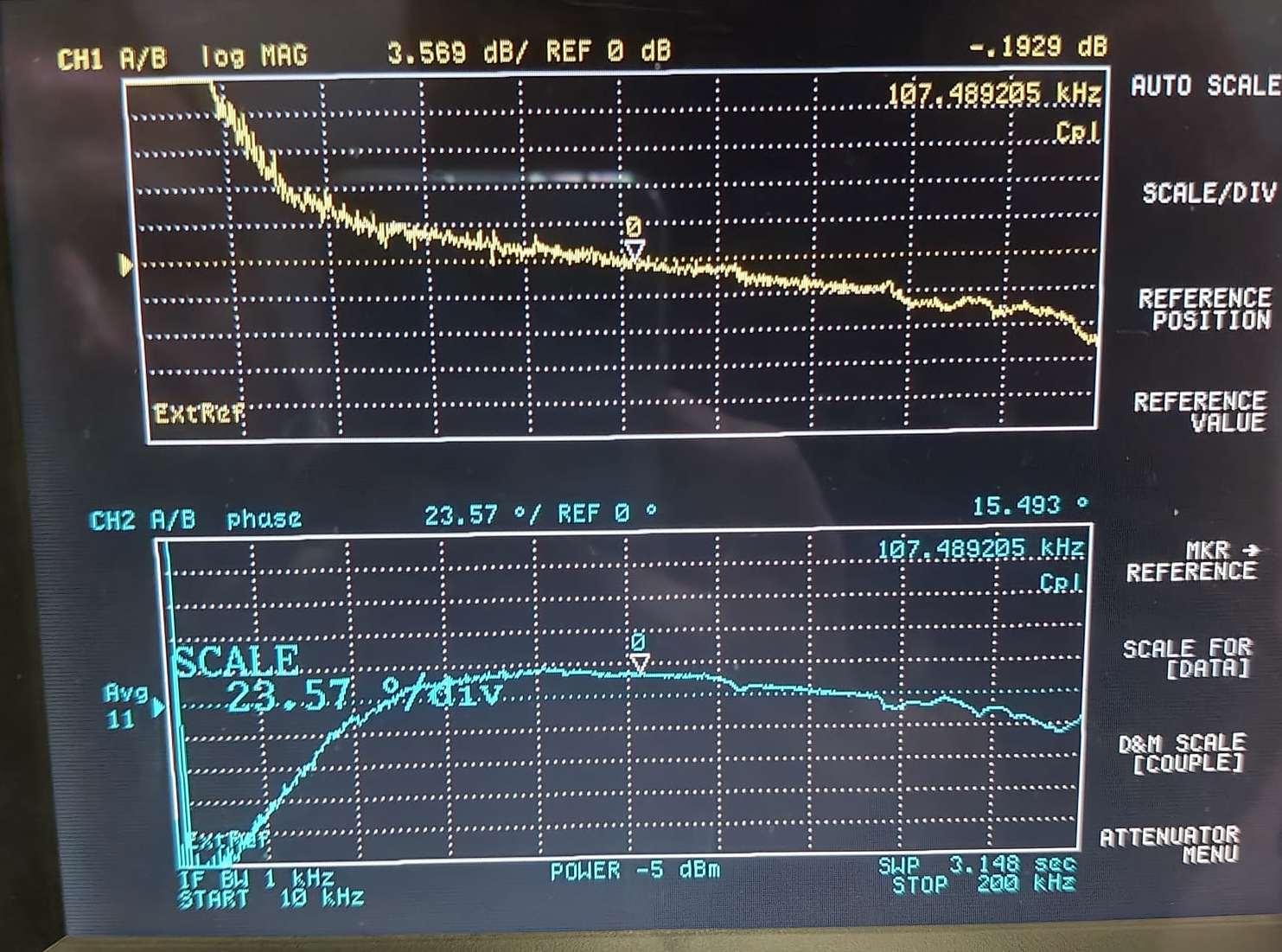
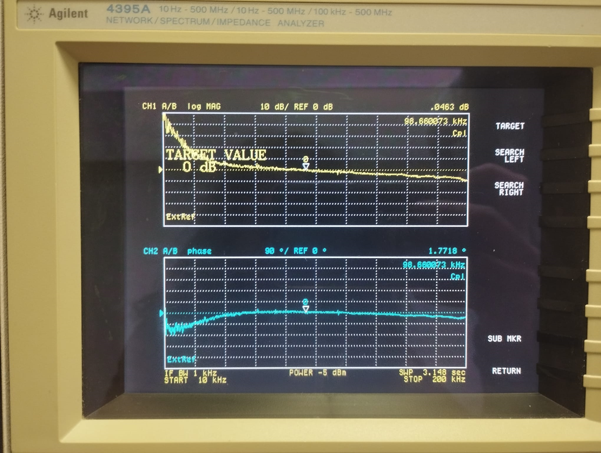
We first measure the OLTF of the IMC loop and found an UGF of 107 kHz with 15 degrees of phase margin (figure 1)
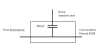
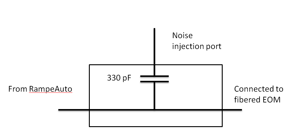
We installed the electronic box that JPC designed to do the injections (figure 2) and check any effect principally on SIB2_RFC_8MHz with different impedance on the noise injection port:
- nothing connected : no effect
- 50 Ohms no effects
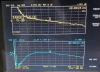
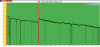
- "0" Ohms : decrease of the noise (see figure 3)
We checked that the box manufactured by EGO electronics group (which is the same but smaller) the results were the same.
We let this last one connected.
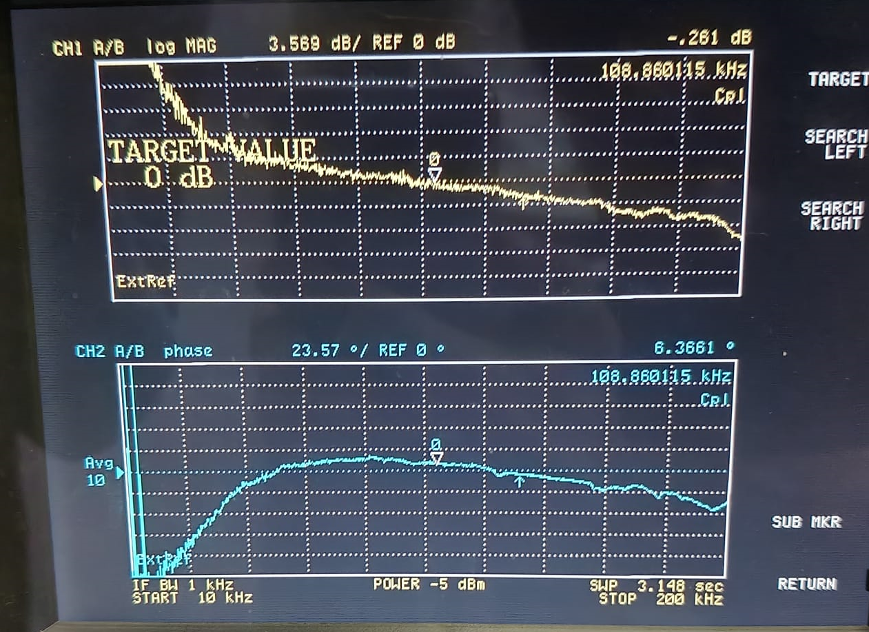
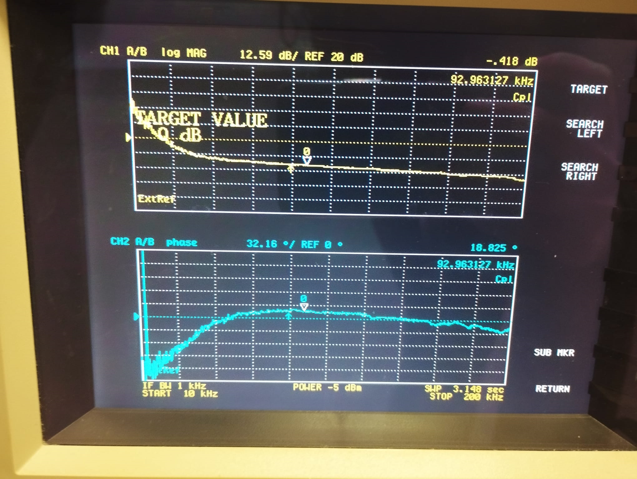
We checked the OLTF of the IMC. As expected we had quite a huge decrease of the phase margin. With the variable attenuation on the error signal set to 22 dB as it was before the intervention we had still an UGF of 108 kHz but a phase margin of 6.4 degrees.
In the firt tests of the morning we actually only decreased the attenuation thinking that we were decreasing the gain.
Obviously we did not manage to restore an acceptable phase margin for the loop. Anyway it worked (with an increase of frequency noise) from the intervention till the afternoon with 20 dB of attenuation
We went back in piscina at the beginning of the afternoon shift to increase the attenuation again to 22dB (fig 4).
We relocked in LN2 for 1h from 16h15 UTC ti 17h15 UTC, then we went in LN3.
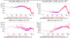
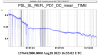
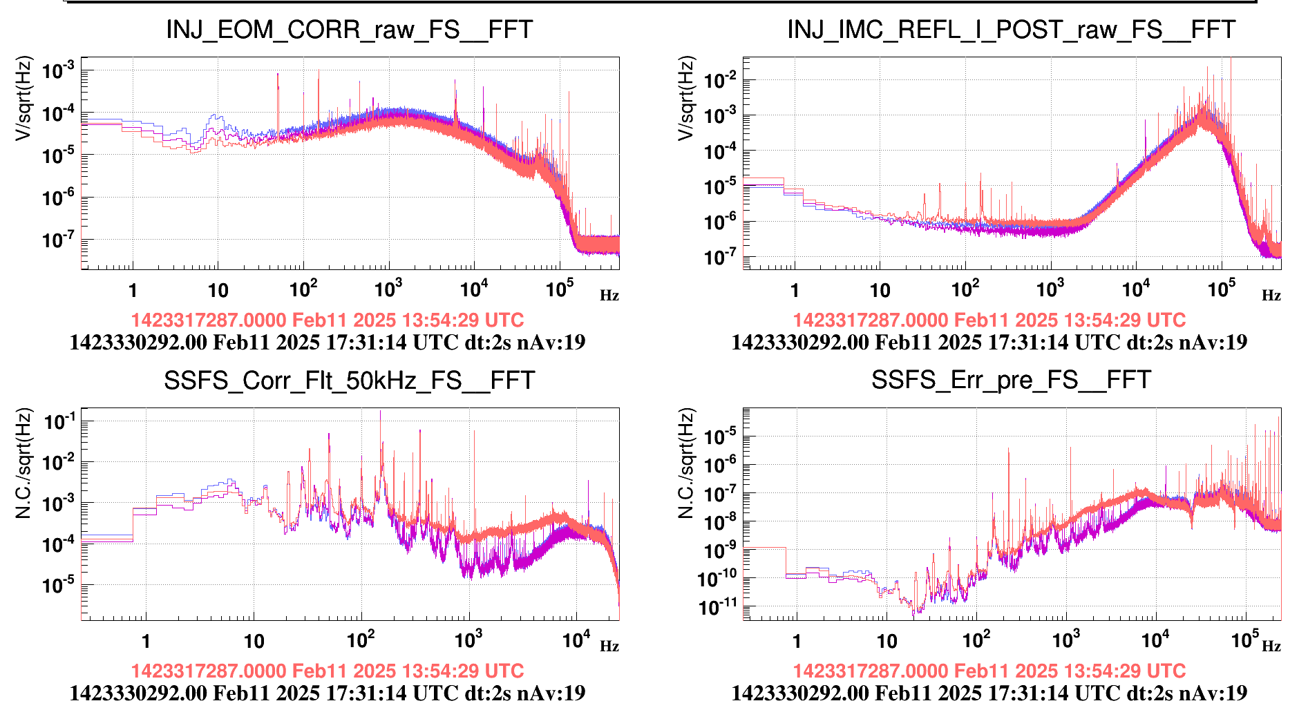
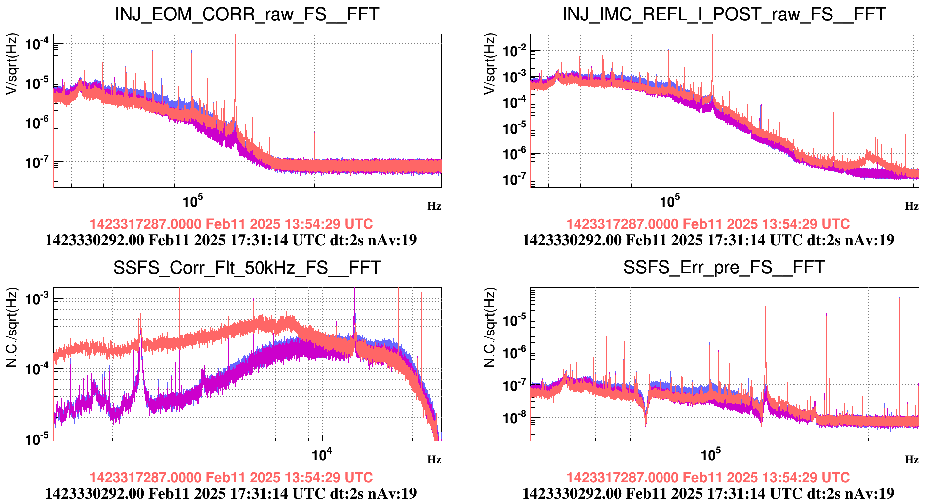
Fig 5 and 6 (zoom at high freq) show the spectra of the IMC error signal, corrections and SSFS. With 20dB attenuation (orange) we had too much gain. We then increased the attenuation by 2dB (blue curve) and the spectra of the SSFS in LN3 are similar to last night.
We leave the filter on the EOM corrections in place.
.png)


.png)