In order to acquire some references before the WI CO2 laser replacement, three different HWS-INJ measurements have been performed.
Measurement #1
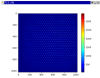
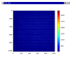
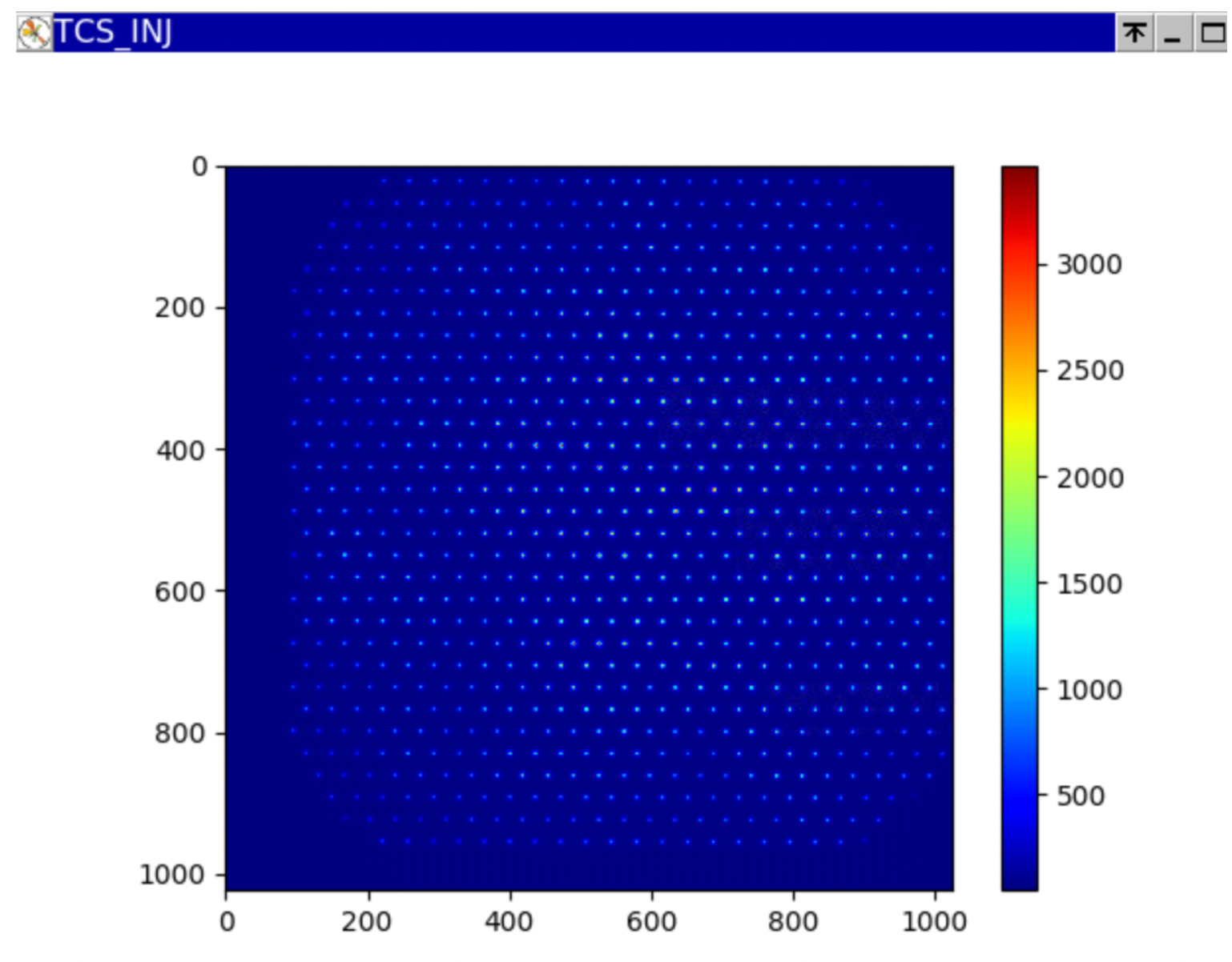
The illumination of HWS-INJ before starting the measurement #1 is shown in fig.1.
The list of the actions are listed below:
06.55 UTC: ITF manually unlocked and and arms locked on IR
07.53 UTC: WI single bounce configuration
07.58 UTC: START HWS–INJ acquisition (Folder 20240720T0958)
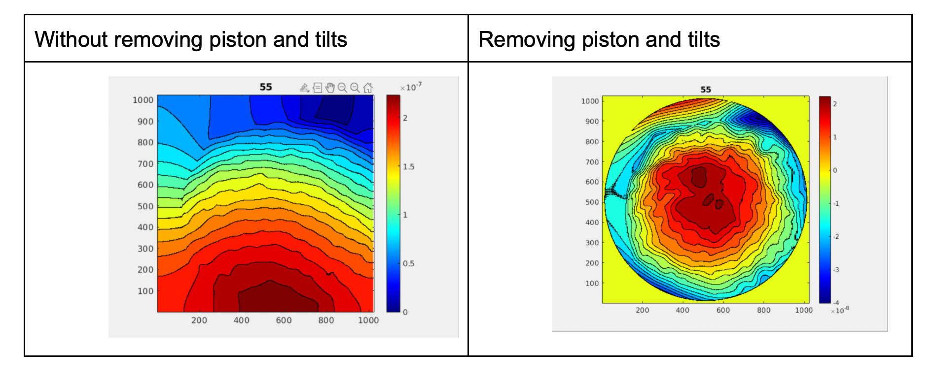
08.08 UTC-08.12: Increase of the WI OUTER ring power. Completed at WF 14 .
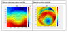
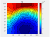
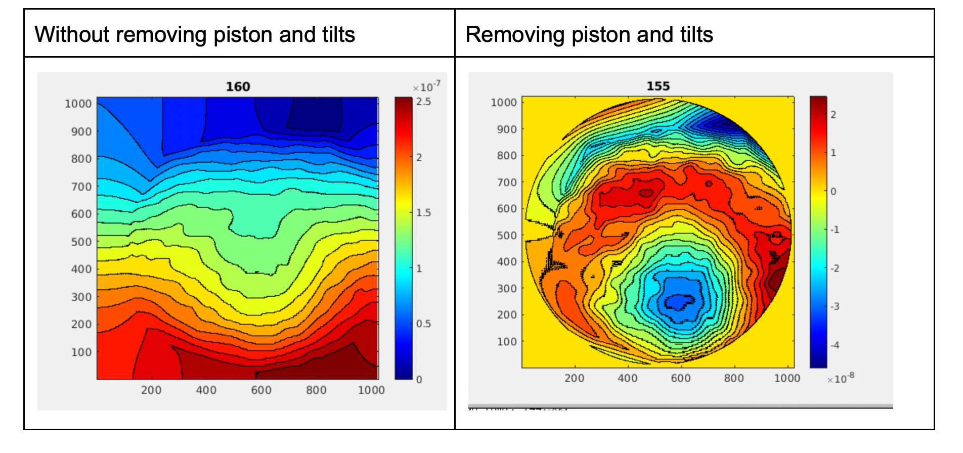
Without piston and tilts, the OPL induced by the increase of the outer ring power is clearly visible in the HWS map. Unfortunately, the OPL is not visible without removing them (see fig.2). Since removing piston and tilt causes the centering information to be lost, between WFs 43-46, I rotated the waveplate to inject the total available power on the outer ring line. I completed this action at 08.46 UTC. I was able to increase the WI pickoff from 0.806 W to 0.904 W , thus the outer ring power from 2.2 W to 2.5 W. The situation didn't improve. To maximize the S/N ratio of the measurement, the only way is to perform the HWS-INJ measurement in the ON/OFF condition of the outer ring. In order to exclude any possible misalignment of the HWS beam on the CP, the WI CH power has been increased (between 10.02 and 10.04 UTC, WFs 120-122) [WI CH pickoff from 0.909 W to 2.8 W].
The OPL induced by CH appears in the HWS-INJ map, removing and without removing the tilt but the measurement result was not so clear (see fig. 3).
At this point, to avoid wrong interpretation of the results of the CH centering, a second acquisition has been performed (measurement #2).
I asked Fabio to relock the arms on the IR and put the ITF again in WI single bounce to perform a measurement during the cooling phase.
Then, I started a new measurement where the reference was taken with the outer ring at the steady state of maximum available power and CH at high power. The differential measurements were performed by closing the flip mirror of CH.
Measurement #2
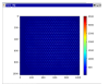
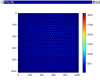
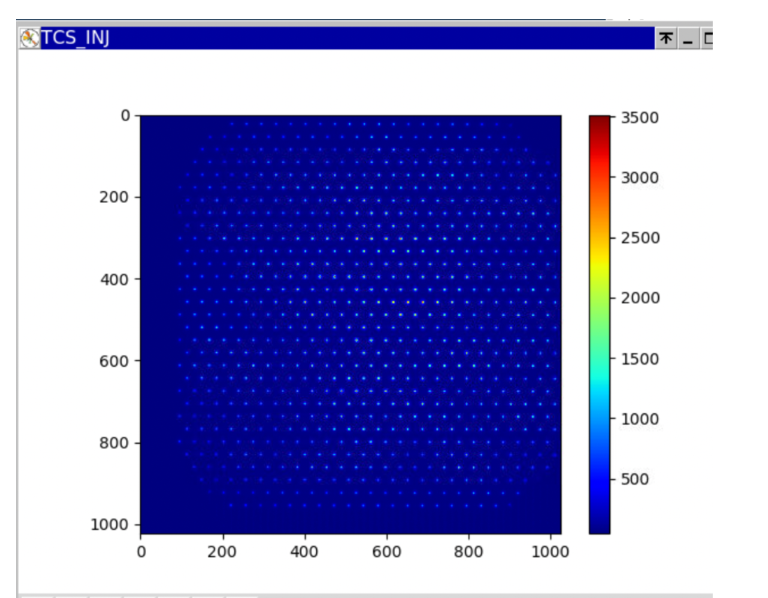
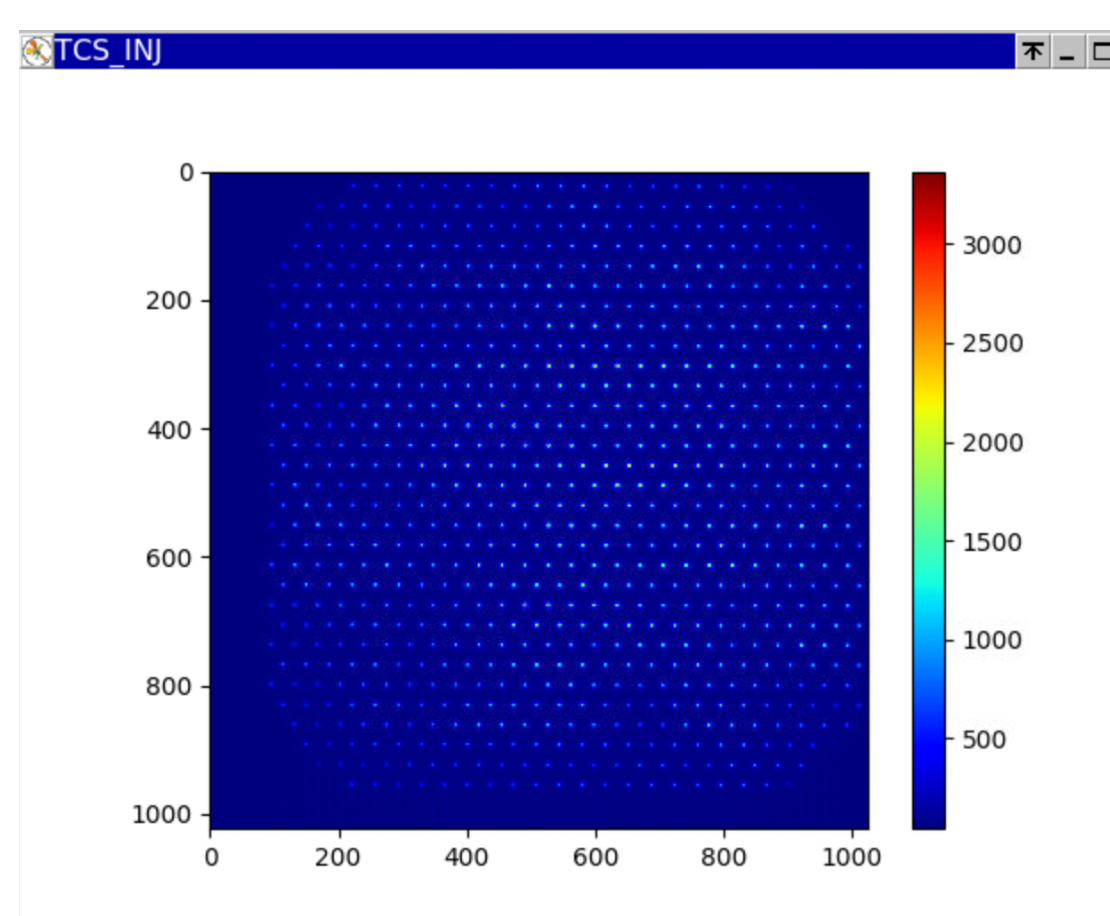
The illumination of the HWS-INJ before starting this second measurement is shown in fig.4.
Here the list of actions:
10.53 UTC: HWS-INJ acquisition started (Folder 20240720T1253)
11.01 UTC: WI CH flip mirror closed (WF 9)
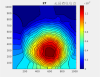
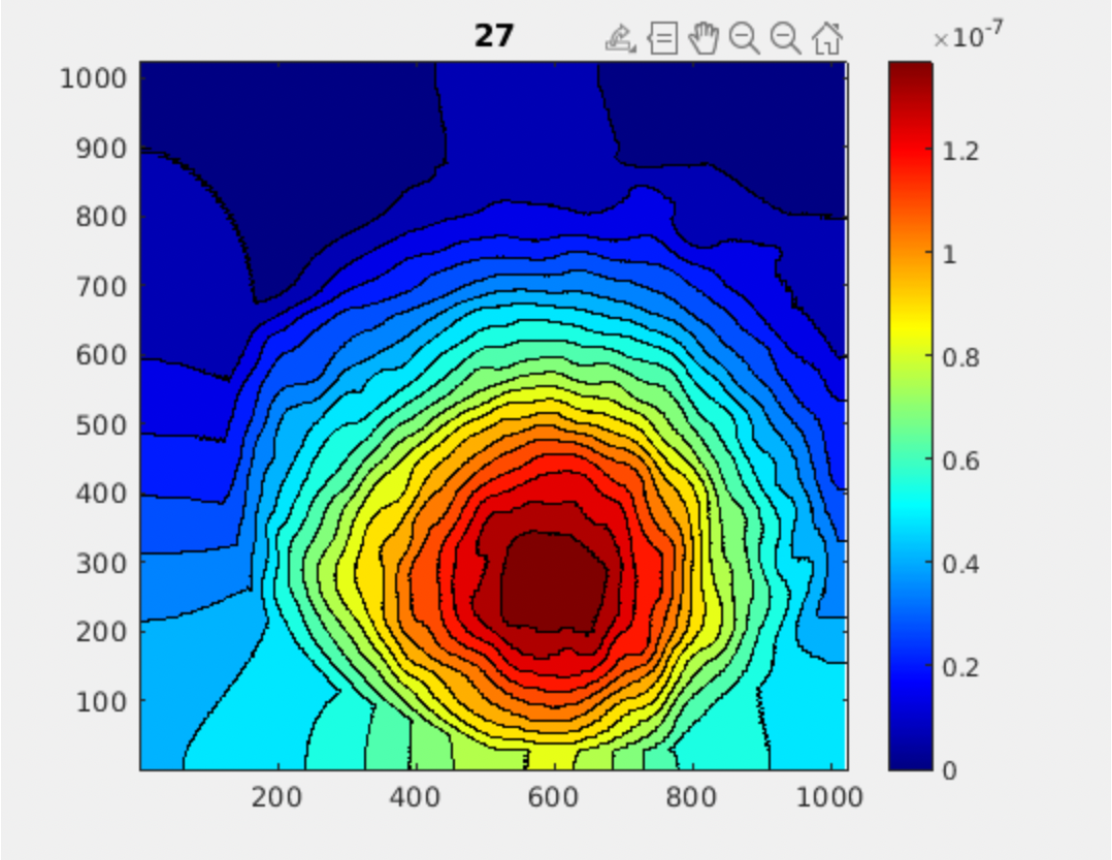
The OPL due to CH switching off appeared well visible in the map (see fig. 5). Thus, the HWS-INJ beam is quite well aligned in the horizontal direction, not so good in the vertical one.
At this point, I proceeded with the last measurement with HWS-INJ, taking the outer ring at the maximum available power as a reference condition. The differential measurements have been performed by closing the WI OUT flip mirror (measurement #3).
Between the end of the CH measurement and the beginning of the new one (to allow the thermalization of the CH off), the ITF has been left with the arms locked on IR.
Measurement #3
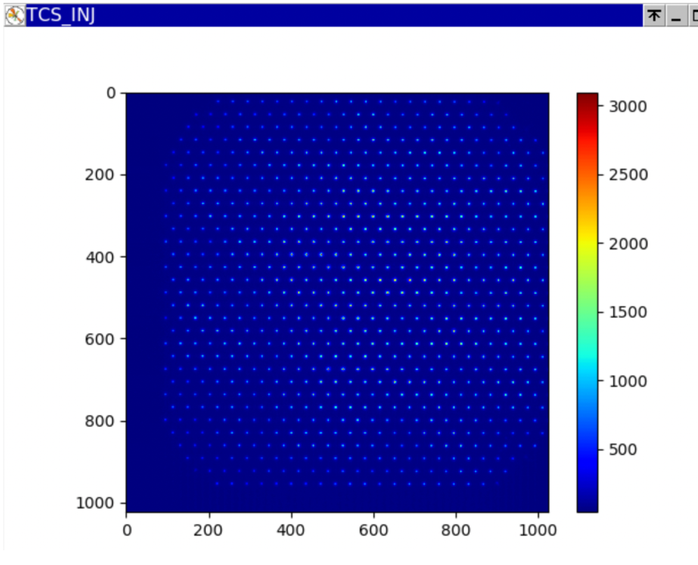
HWS-INJ illumination before starting the measurement is shown in fig. 6.
Here the list of actions:
12.11 UTC: HWS-INJ acquisition started (20240720T1411) in WI single bounce
12.18 UTC: WI OUTER flip mirror closed (WF 7)
13.48 UTC: HWS-INJ measurement interrupted (WF 93)
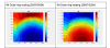
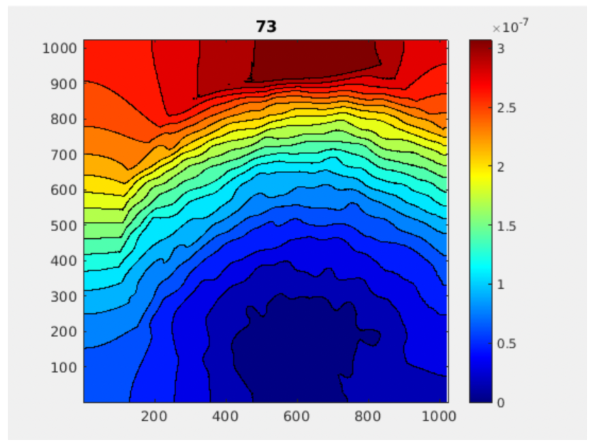
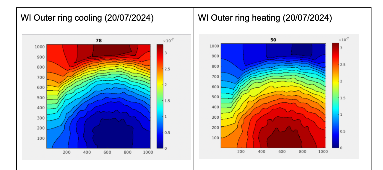
In this measurement, the HWS maps are more clear, the outer ring OPL is visible in the blue area in the lower part of the map (see fig. 7).
Unfortunately, the HWS beam is quite misaligned in the vertical direction, making it extremely difficult to identify the centering coordinates.
At the end of the shift, I resettled all CO2 nominal powers (completed at 14.11 UTC).
