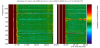
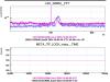
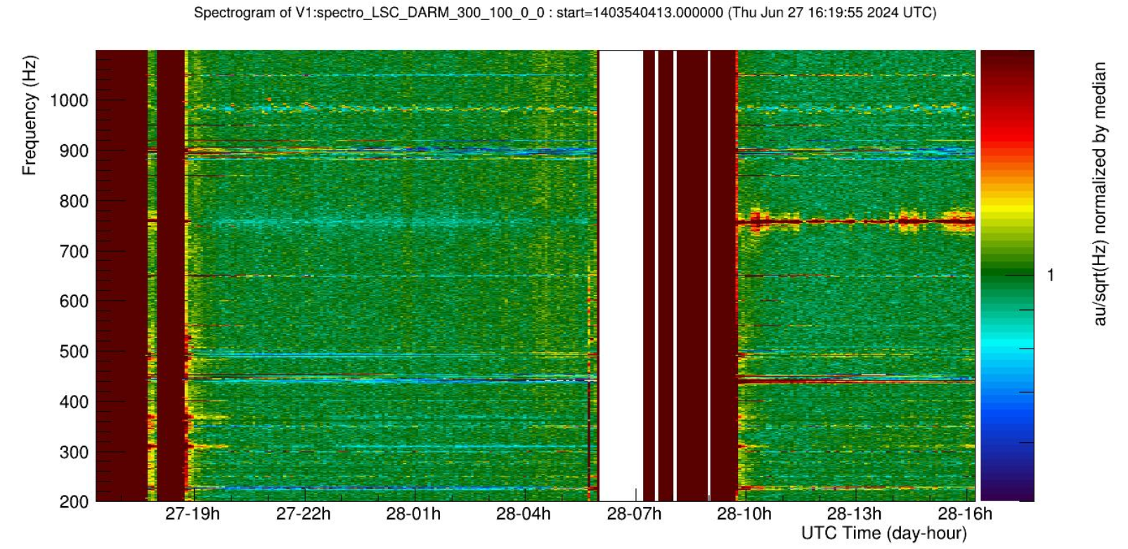
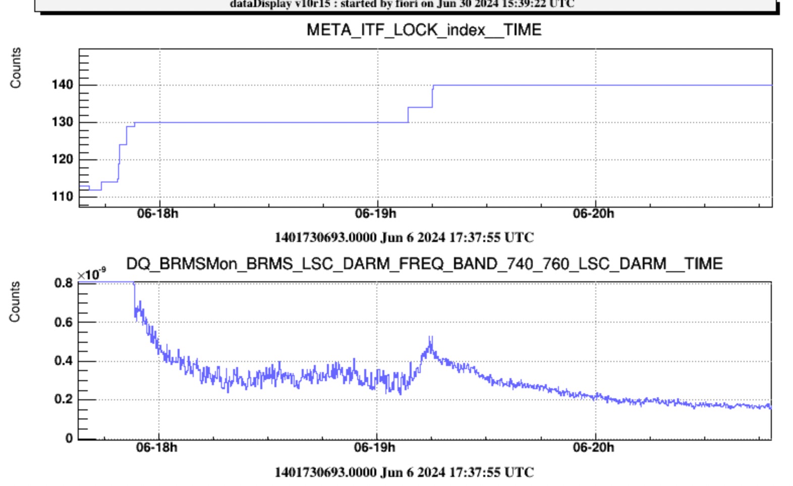
Figure 1. A new line has started at ~760Hz this morning after the relock. This may be due to the squeezer which has been turned off after issues this morning following the earthquake: https://logbook.virgo-gw.eu/virgo/?r=64610
Figure 1. A new line has started at ~760Hz this morning after the relock. This may be due to the squeezer which has been turned off after issues this morning following the earthquake: https://logbook.virgo-gw.eu/virgo/?r=64610
Quite surprisingly, neither the daily runs of BruCo nor a dedicated one when the 760 Hz line was strongest produced any results for the coherence of this with other auxiliary channels. From an inspection of the spectrogram around this frequency, the new line appears to vary in both amplitude and frequency, and at times couple with a number of low-frequency lines producing a wide sideband structure.
If the hypothesis of a squeezing-related origin could be confirmed, more targeted analyzes could be attempted on the channels representing the changes to this subsystem after the earthquake. I await input from the experts.
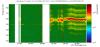
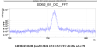
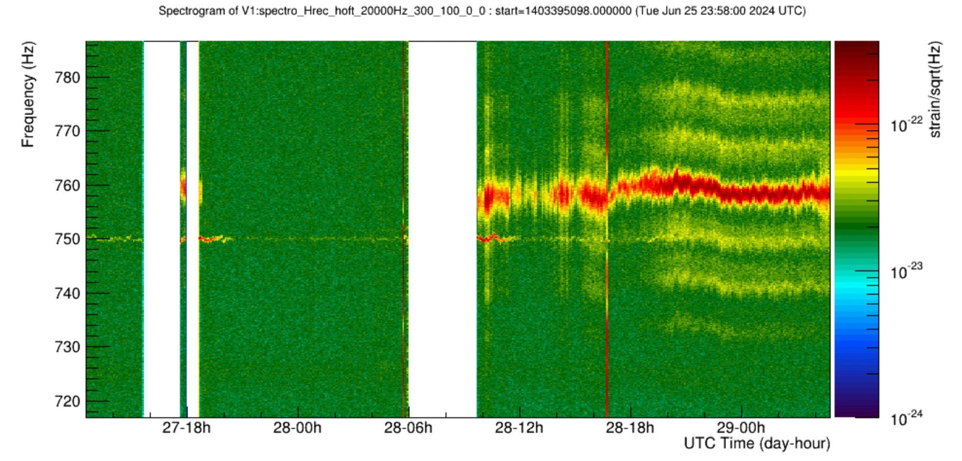
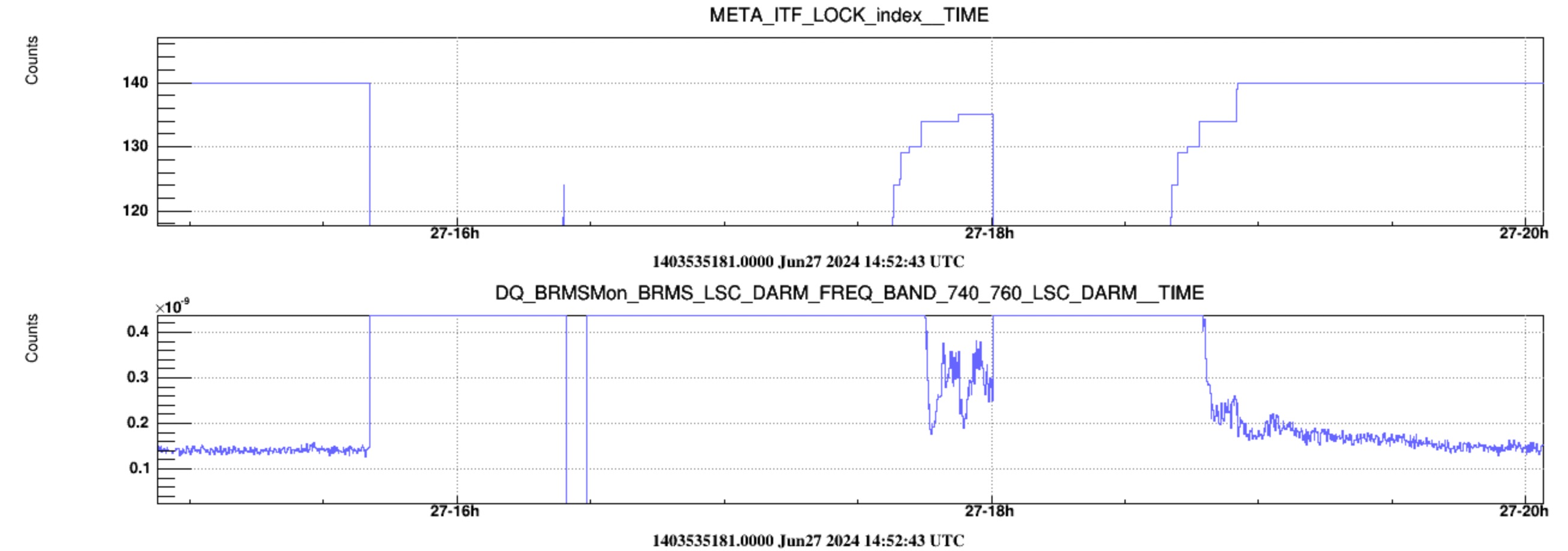
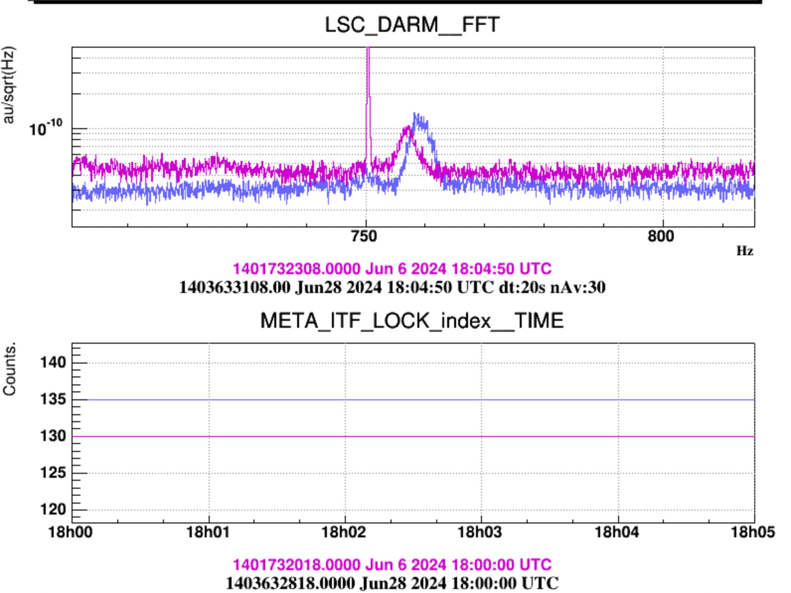
The spectrogram in Figure 1 shows that the same (or anyhow very similar) structure at 760 Hz appeared shortly also on June 27th. The noise was there during the short lock of ~18:30 UTC which reached up to state 135. Then, in the following lock the structure stayed on for the few minutes during state 135 and than it faded away after reaching state 140 (Fig.3).
I checked also past times, and this behaviour seems recurrent: the line appears in state 135, than it disappears after a few minutes in state 140. Yet, now it persists in state 140... Sorry my ignorance about the states coding.
This is a very nice observation, and confirms that squeezing is the issue. State 135 correspond to LN3 without squeezing, and state 140 to LN3 with squeezing.
Squeezing has been disabled since Friday due to an issue with the automation and the sub-carrier: https://logbook.virgo-gw.eu/virgo/?r=64618
So squeezing when disabled adds this line at 760Hz. The reasons for that need to be understood.
I checked the line at 760 Hz and I confirm that is an effect due by Squeezing.
When we inject squeezing ing to the intereferometer we need that our laser is at the same frequency of Virgo PSL laser to generate SQZ states at the same frquency of the laser light into the interferometer.
This is done by locking the Main Laser of the SQZ to the Virgo Laser via a PLL loop. The main laser of Virgo is brought between INJ and DET lab with a 50 m optical fibre. Before sending the laser into the fibre the laser is frequency shifted by 80MHz with an AOM. Thus t lock the two Lasers at the same frequency we close the PLL loop with an offset of -80MHz. The two 80MHz generators are not locked together, both of them are generated with a DDS chip (AD9910) that uses as reference clock a 500MHz wenzel OCXO thus can be a small DC offset between the two frequency generators.
In addition once the squeezed light is injected into the interferometer the fluctuating optical path induces phase noise fluctuation to the squeezing ellipse. These oscillation are corrected by the coherent control loop. The AC correction of the CC loops are used to suppress these fluctuations, but the DC working point is the exact offset that corrects the frequency of the main Laser.
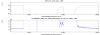
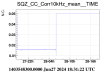
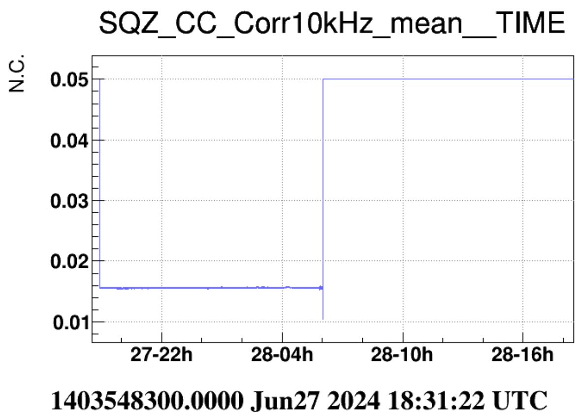
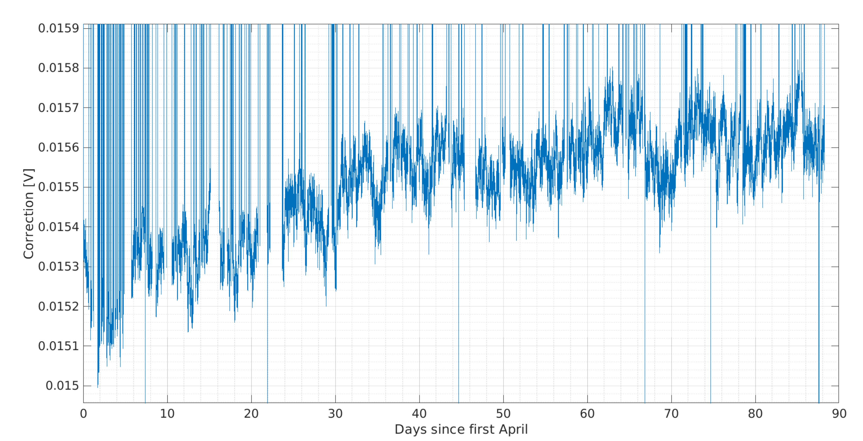
As it is shown in Fig.1 when we unlocked the squeezing we moved the DC set point of the CC loop from 0.0156V to 0.05V this would change the relative frequency between the SQZ laser and the virgo Laser. Thus if some scattered light from the SQZ box reaches the interferometer it would create a peak at the frequency difference. Doing the comuptation 760Hz/(0.06-0.0156)~22000Hz/V. I remembered that the setting of the generator for the CC loop were 44kHz/V i.e. a factor two more, this is confirmed also by the table in this entry.
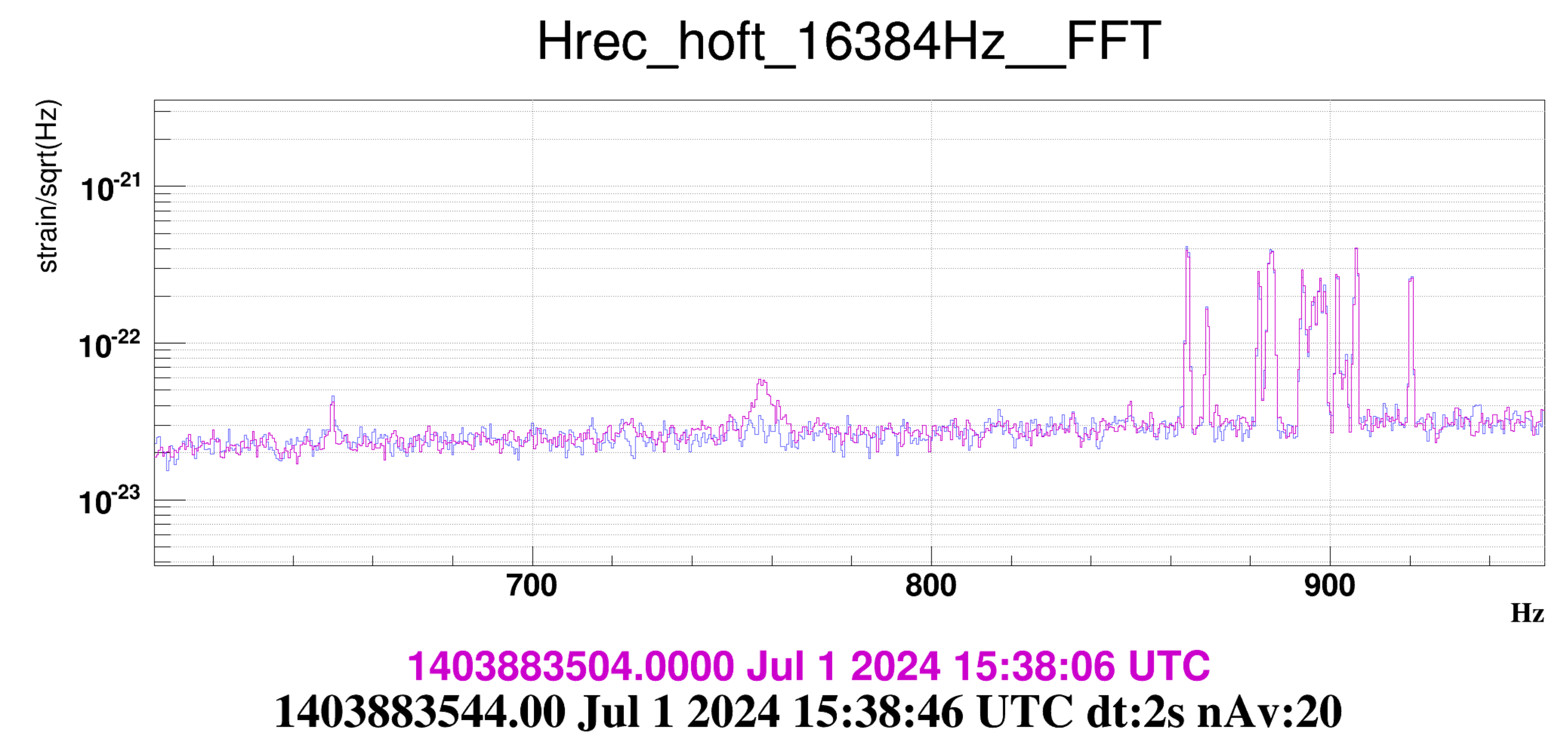
In any case before the beginning of the today shift I asked to have 5 minutes in wich I manually moved the CC set point from 0.05V to 0.0156V and after that the 760Hz peak disappeared (Fig2). I did this at 15:38:40 UTC. This had not solved the issue but moved the effect of the stray light in DC.
I cross checked if the locking point of the CC loop moved during the last three months and it was not the case Fig3. Considering the 22kHz/V factor the point moved by about 8Hz in 3 Months. At the end of this operation I saved 0.0156V as starting point in the SQZ_MAIN.ini file thus the problem hopefully will not happen anymore.
In any case where this scattered light is coming?
When we are locked in LN3 we have the OPA unlocked (in Scan mode), the shutter after the breadbor that is closed (Fast Shutter), the SC shutter is closed and the LO shutter is closed. From the OPA we don't expect "bright" photons at this frequency, the only bright field is the CC field that is frequency shifted by 4MHz. The SC beam is frequency shifted by 1.26GHz so we don't expect scattered light at this frequency. The only field at the same frequency of the squeezer is the LO. Its shutter is closed and it is not doing the same path of the squeezed photons toward the OPA, thus for me it is suprising that some scattered light from it could reach the ITF. To confirm this hypothesis we can do the following tests:
I hope this entry clarified a bit the issue
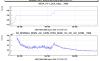
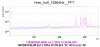
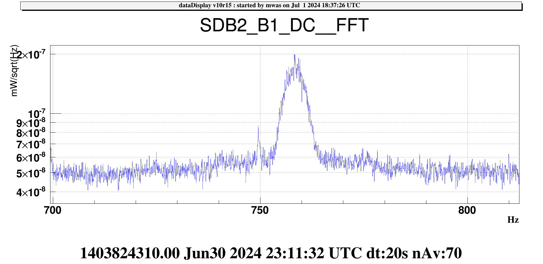
Quantifying the power of the scattered light from squeezing can help in understanding where it comes from despite the closed shutters and unlocked cavities.
Figure 1 shows the line in terms of power on B1. It has width of ~10Hz for a height of ~1.5e-7 mW/rtHz, so an RMS amplitude of ~4.5e-7 mW. This line is due to the beat between the 6.3mW of DARM DC read-out offset and the light coming from squeezing. Hence the power of the squezing stray light must be 3e-14mW = 3e-17W, so the sqrt(6.3*3e-14) = 4.5e-7.
One should measure what is the residual transmission of the fast shutter and estimate the unlocked OPA transmission, to see if it is plausible that it just the residual transmission of a beam that in principle is blocked. Of course, scattered light is also a plausible path to go around the shutter with such a low power.

