Reports 1-1 of 1 Clear search Modify search
AdV-ISC (Commissioning up to first full interferometer lock)
mantovani, tringali, fiori - 11:24 Tuesday 05 March 2024 (63491) Print this report
EIB scattered light noise on SRCL and others

During high microseismic activities it was visible a large worsening on the SRCL noise at low frequency.

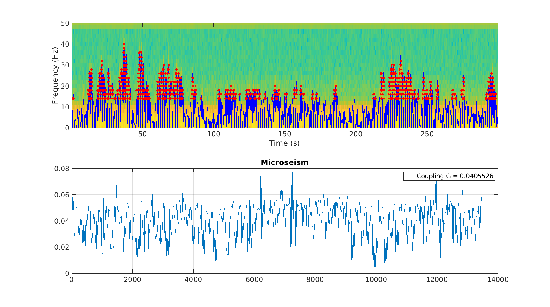
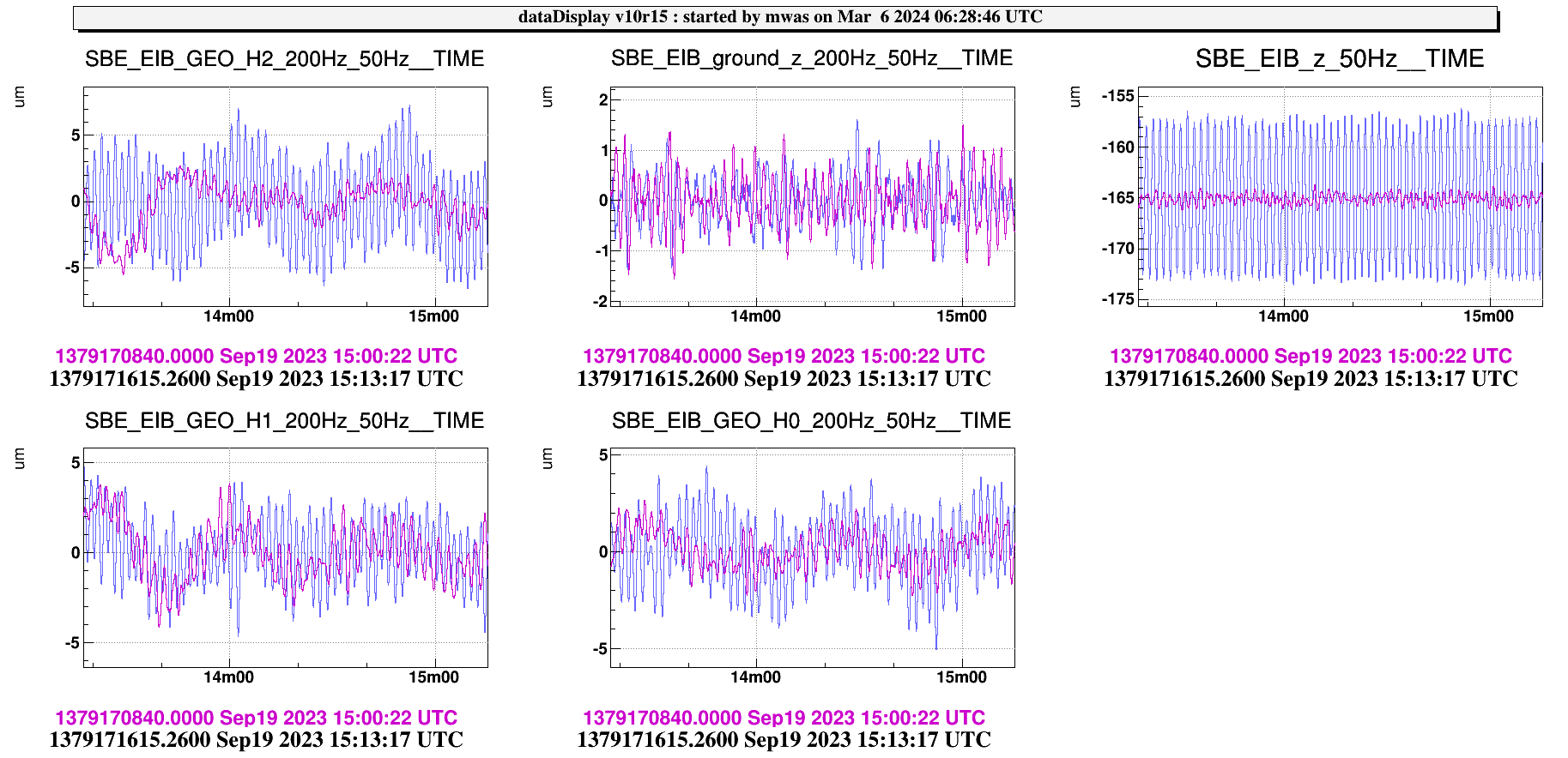
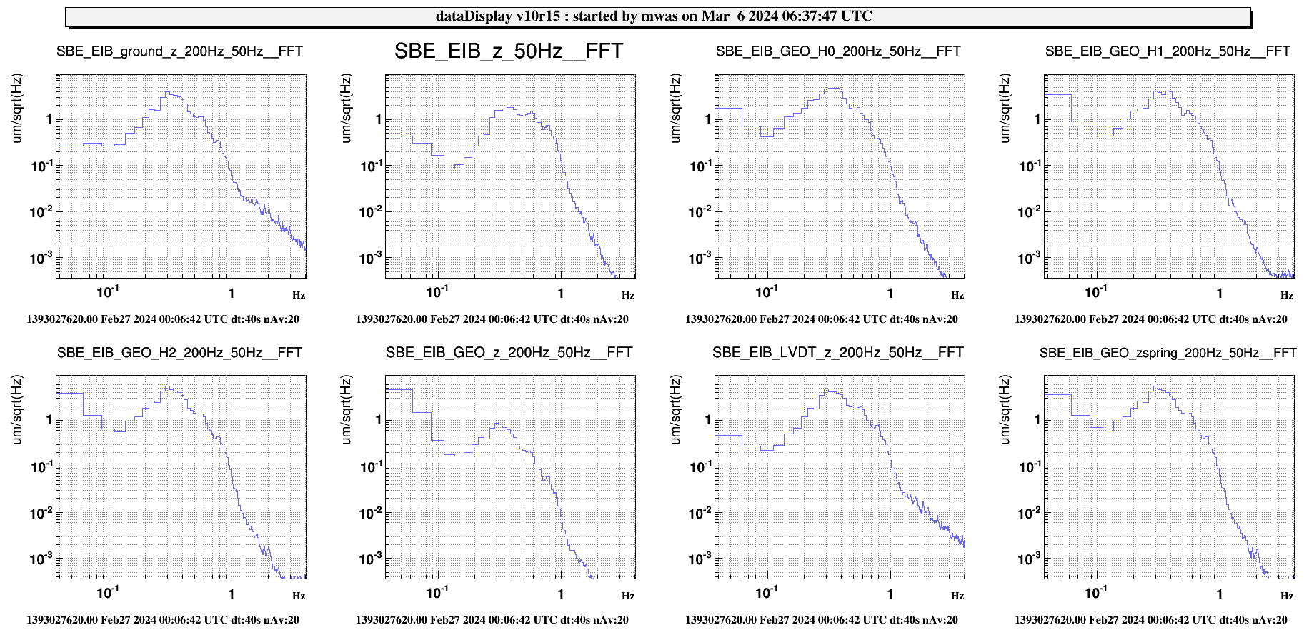
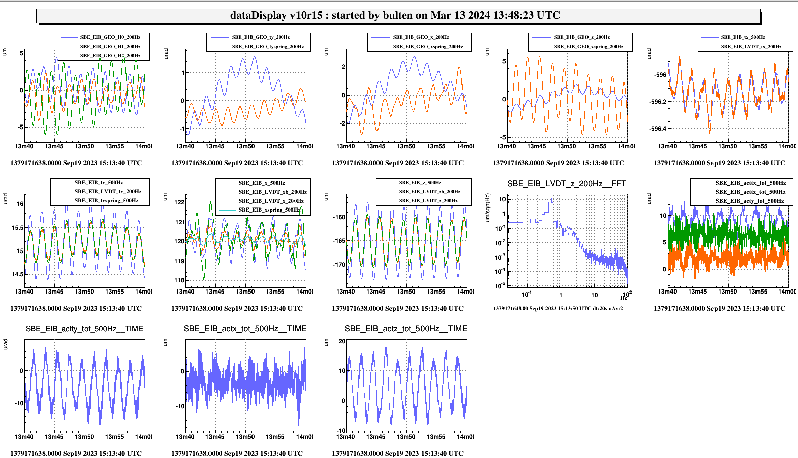
It was clearly visible on the time-fft of SRCL the arches of Scattered light. We have studied various sensors and we identified the best match on SBE_EIB_GEO_H2_200Hz (sensor of EIB displacement logentry 63440, which has a calibration of 1.2).

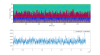
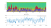
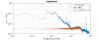
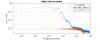
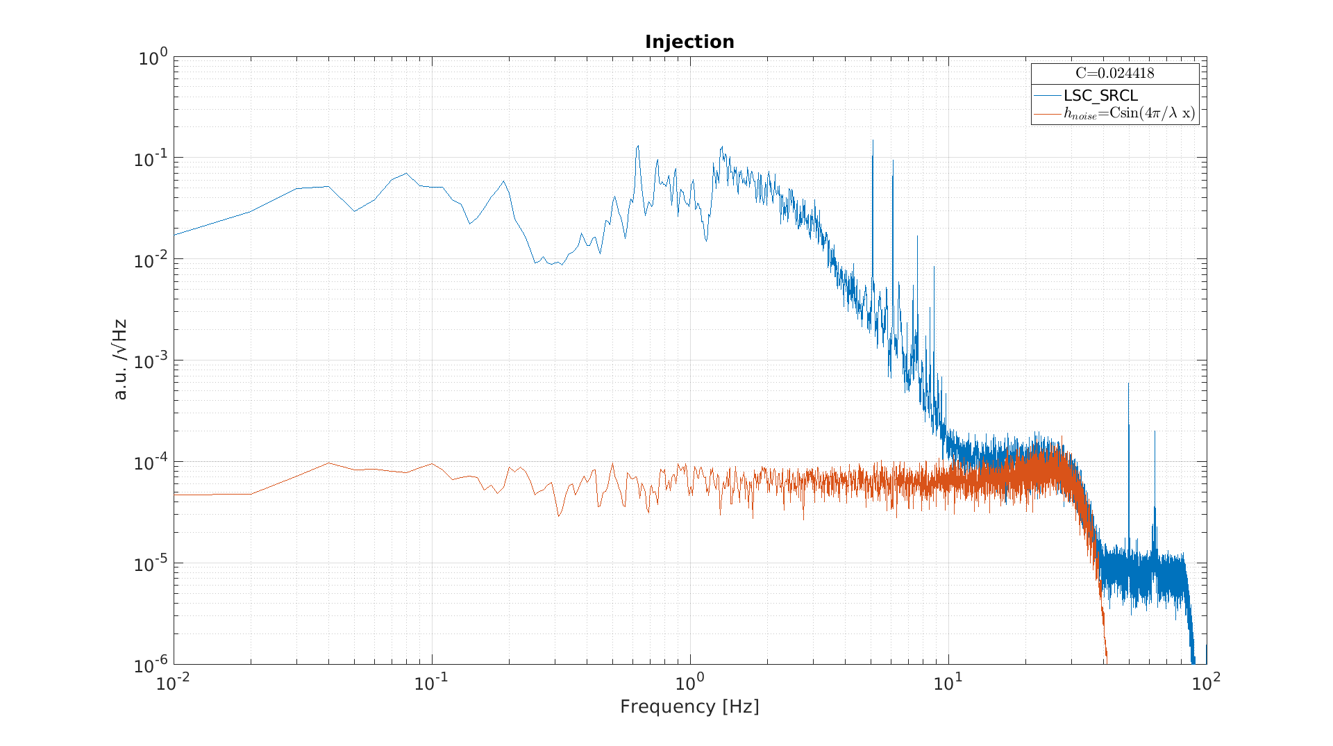
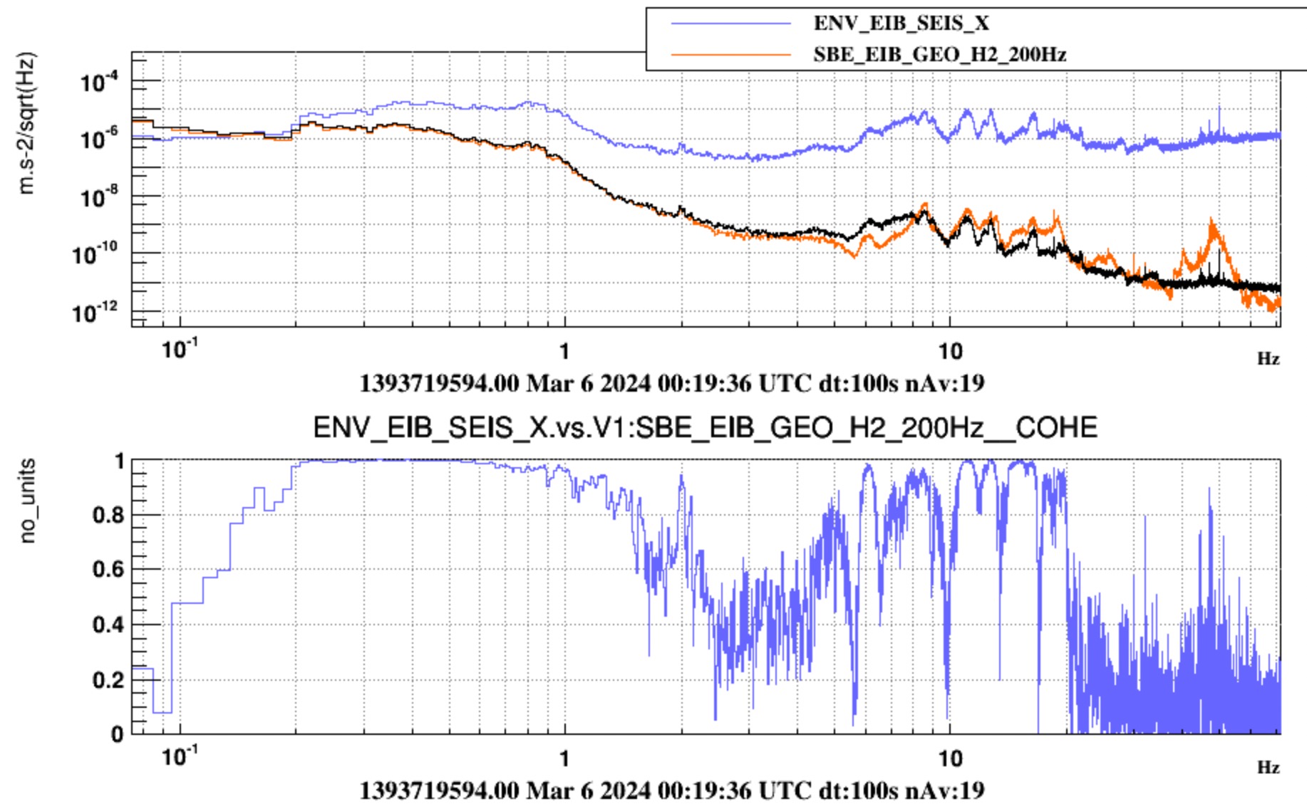
We then used the past injection on EIB (september 27 15:11UTC along z log entry 61713) to measure the coupling which is G = 0.024 (in ASD), see Figure 1; Using this value we can project it on SRCL, see Figure 2.

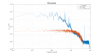
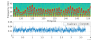
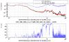
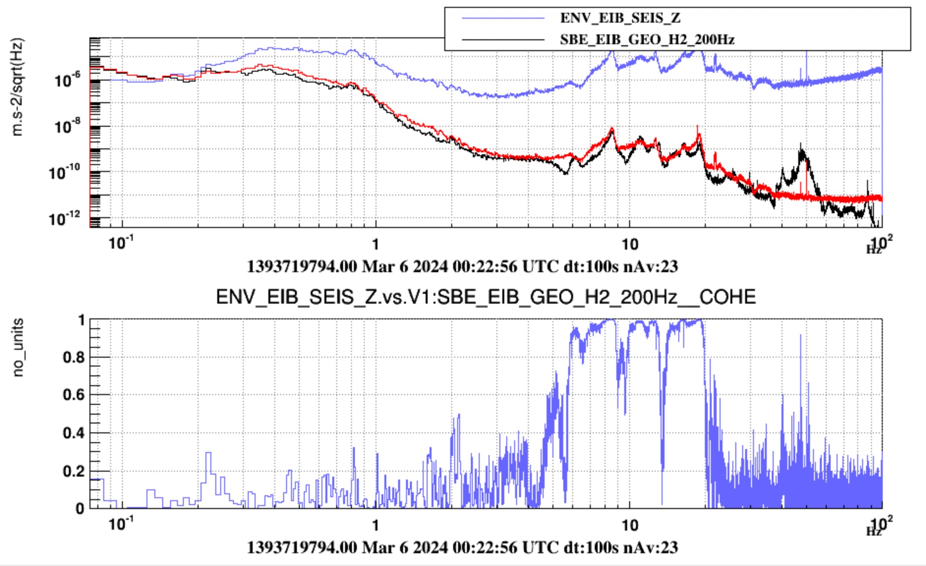
We have then repeated the same analysis on the high microsesim data (27th of February 04:18UTC) and we got a G =0.041 (worsening of a factor 2), see Figure 3 and 4.

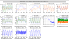
The G value has been measured taking the max value in a smal region around the fringes reconstructed by the seismic sensor calibrated by eye, overlapping the arches, so a small error could be present, a zoom is visible in Figure 5.

The effect on SRCL is very large and further analysis are needed since SRCL is one of the largest contributors to the sensitivity at low frequency.

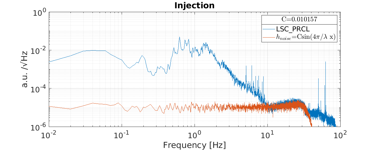
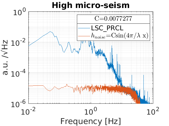
The coupling mechanism seems to be trought frequency noise since the arches are visible on PRCL, RFC 6MHz I, see figure 6-8, and not on the B2 QPDs (not jitter).


Images attached to this report
Comments to this report:
mwas - 7:55 Wednesday 06 March 2024 (63501) Print this report

Figure 1, looking at SBE position modulation from Sep 19 last year the H2 geophone is the the horizontal geophone that is most aligned with the z direction. Is that the north-south or the east-west direction?

Figure 2 during the high micro-seismic time the motion of the ground and the motion seen directly by the geophone has a similar amplitude at 0.3Hz, but it is a factor two lower in the reconstructed bench motion that is in-loop (EIB_z) and a factor 4 in the tilt corrected geophone signal (EIB_GEO_z). There might be an issue here in the control scheme or control for EIB.

Images attached to this comment
fiori - 17:32 Wednesday 06 March 2024 (63505) Print this report

To answer the first point:

we convinced us that geophone channel SBE_EIB_GEO_H2_200Hz points from the EIB towards the ITF, that is the Virgo NS

Figures 1 and 2 here are coherences of the GEO channel with the two horizontal channles of the ENV episensor onto the EIB bench. Figure 1 is with ENV_EIB_SEIS_X which points towards ITF (conventional "X", according to naming conventions VIR-0223B-14). Figure 2 is  with the ENV_EIB_SEIS_Z which points towards the IMC (conventionally called "Z") (see also Rosario's https://logbook.virgo-gw.eu/virgo/?r=63447). Here the GEO channel has been converted into units of meters and the episensor (acc) channel has beed doubly integrated.

You can see that in the microseism region the coherent channels are SBE_EIB_GEO_H2_200Hz and ENV_EIB_SEIS_X. Also the calibration looks consistent.

Images attached to this comment
bulten - 16:17 Wednesday 13 March 2024 (63592) Print this report
I inspected all spectra from the noise injections on Sept 27, and I indeed think that Michal is right and there is a mistake in the config file of SBE-EIB.
I think the mistake is in the geophones on the bench; I think for Ty and Z we have a wrong sign.
The plot included here contains time signals of the injected noise in z, 10 murad at 0.5 Hz. In panel 8 the z-position of the bench and springbox from
the LVDT is plotted, where LVDT_z gives the z-reading of the LVDT and LVDT_zb is this signal plus a high-pass filtered ground noise signal; LVDT_zb
should be the position of the bench from which the ground motion is subtracted. You see that the ground motions for LVDT_x,y,z and LVDT_xb,yb,zb do
almost coincide; the grpound correction is small.
The first panel gives the geophone filtered displacement signals for the three horizontal gephones, where H2 is pointing towards the input mode cleaner
(EIB_z direction) and 0 and 1 are under 120 and 240 deg. of this direction. The sign seems correct, amplitude of H2 is about -2 times the amplitudes of H0 and H1.
You can see that we also have some TY-admixture.
The injection is done in closed loop; you can see that apart from z, we also need actuation in Ty and Tx to keep these angles stable. That is due to the tilt
stabilization system. The bench is so soft in Tx and tz that we have some springs helping to increase the stiffness and these couple the horizontal movements in
x and z to the tilt angles Tz and Tx, resp, and also introduce a bit of Ty.
However if we look to GEO_z and GEO_zspring, then we see that GEO_zspring that is reconstructed from GEO_H0,H1, H2 more or less coincides with the LVDT readings
but that GEO_z (which is made from the combination of the geophones on the bench) is almost zero.
I think there is a sign mistake in reconstructing the (monitor) signal GEO_z and GEO_ty and thus also in EIB_z and EIB_ty, which is the blended information from the geophones on
the bench, the geophones on the ground, and the LVDT. Luckily this is not in the control PID loop (which is using the geophones on the spring box); if you make a sign mistake in a geophone
there then the loop is immediately unstable because you provide negative feedback.

In conclusion, I would like a shift to inject noise in Ty in open loop to check all the signs and also all the filters on the horizontal geophones to see if we have made a mistake,
which I think we have. The calibration and/or sign of the horizontal geophones on the bench seems wrong.


Images attached to this comment
Search Help
×

Warning

Error

The present report has been modified outside this window. Please check for its integrity in the main page.

Refreshing this page will move this report into drafts.

×