Reports 1-1 of 1 Clear search Modify search
AdV-ISC (Automatic Alignment)
mantovani, bersanetti - 16:51 Monday 18 December 2023 (62778) Print this report
SR ty alignment with DCP error signal

This morning we tried to consolidate the misaligned configuration for the SR mirror in order to get the best sensitivity in the bucket.

We had the possibility to use 2 signals: the double demodulation of DARM in the bucket or simply the DCP. The first error signal is currently not sensitive to SR alignment (to be checked if a computation problem is present) so, we studied the possibilty to implement the second one.

We then misaligned the SR ty, keeping the SR tx engaged with the standard loop and re-engaging the servo on the BS ty set point (gain 1e-6).

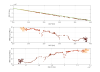
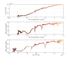
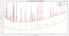
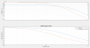
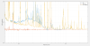
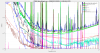
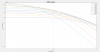
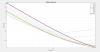
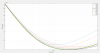
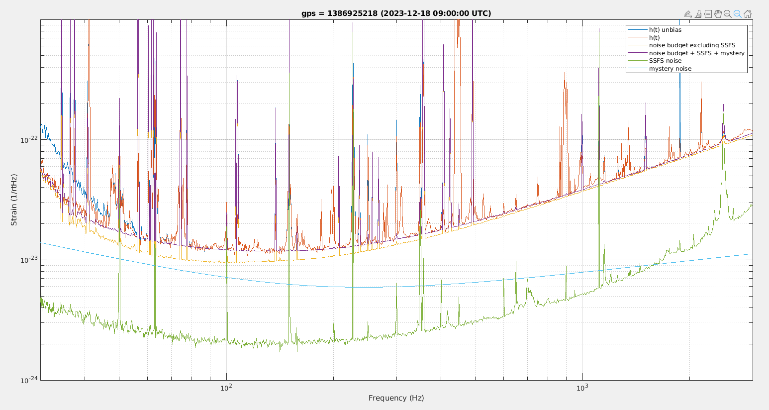
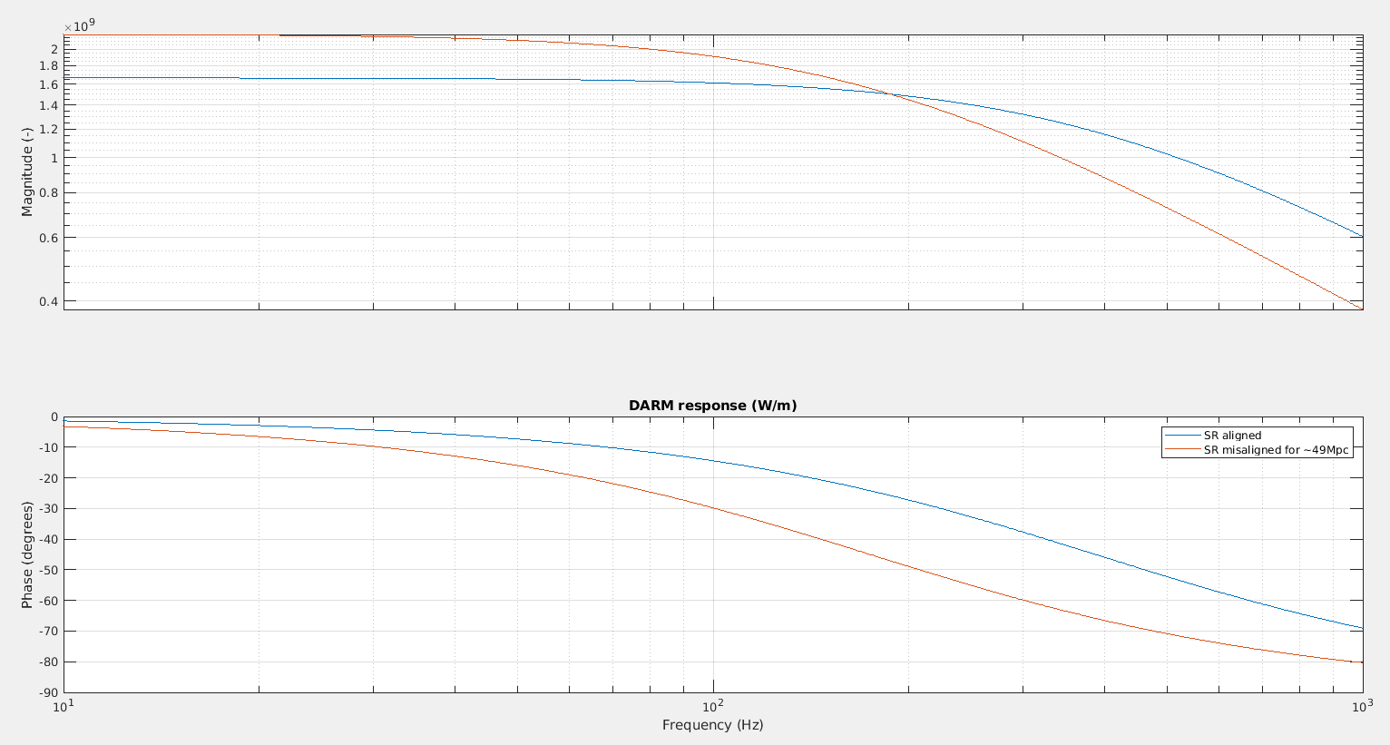
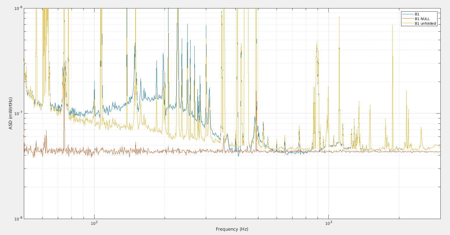
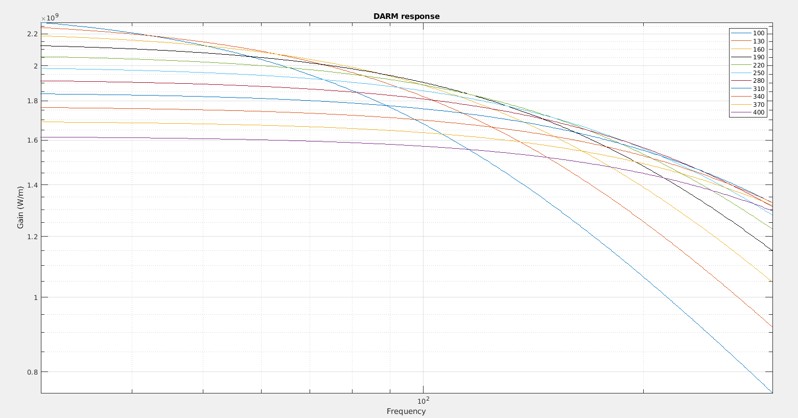
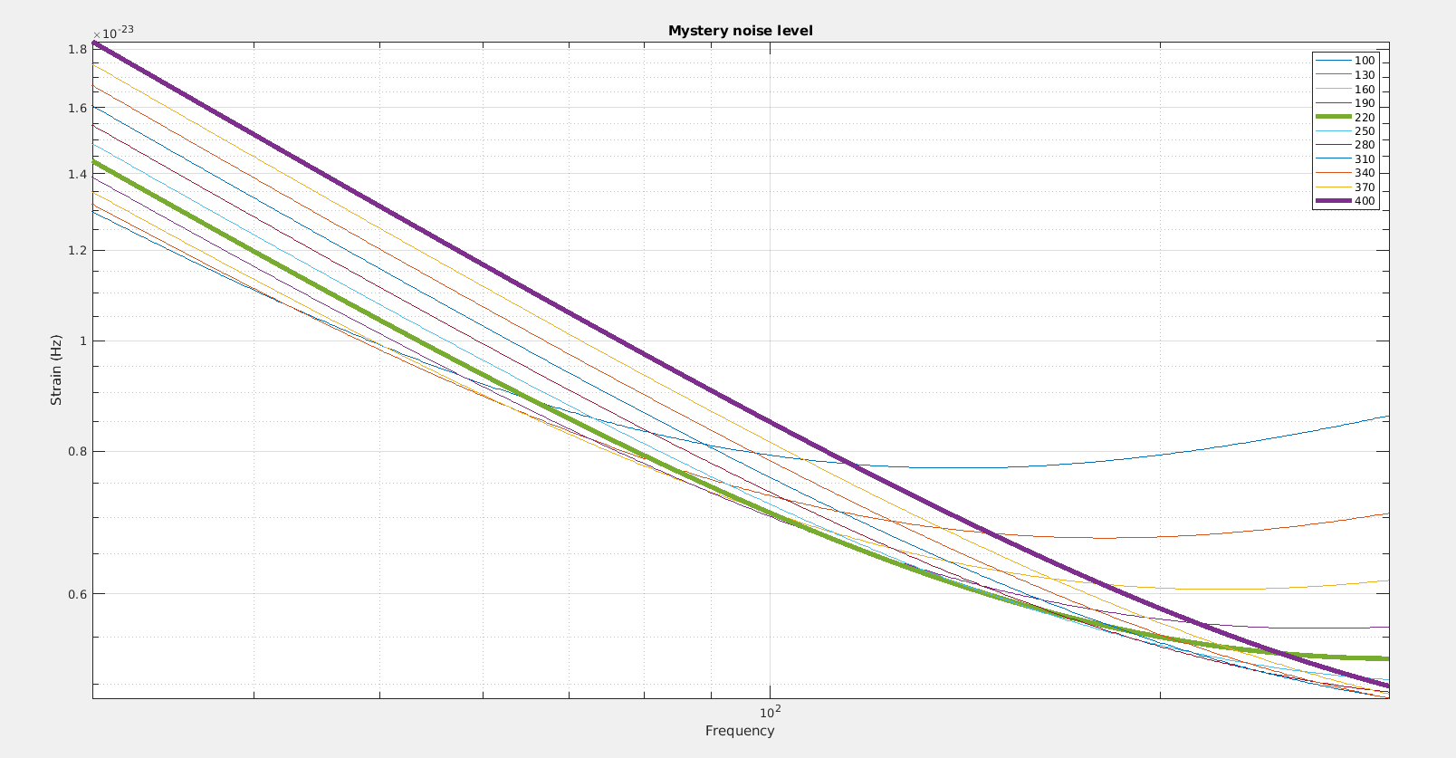
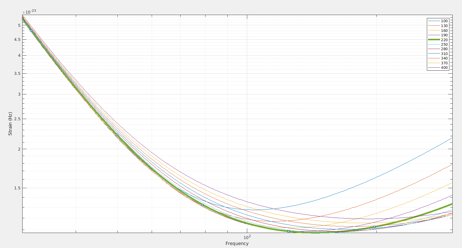
We have reached 50Mpc with a misalignment of SR ty larger than 2urad. See Figure 1 2 and 3, where the effect of the SR alignment is visible (this time the maximum of low frequency OG was not reached even for DCP of about 160Hz).

To be noticed that the SDB powers do not drop (only as small decrease of the 112MHz).

We engaged the new error signal by hand and we unlocked by setting the set point to 150 for a failure of DARM (the pole was too close to the DARM ugf).

We have put in the automation the engagment of the new error signal with a set point of 220Hz of DCP, but we could not test it due to the PSL failure.

---- to come back to the usual alignment control -------------

comment lines 6042-6045 in ITF_LOCK.py

Images attached to this report
Comments to this report:
mwas - 17:29 Monday 18 December 2023 (62779) Print this report

Figure 1 shows the summary noise budget for the with SR misaligned and good BNS range. In this case the mystery noise curve is not a fit to fill the gap in the noise budget. It is noise on B1 fitted on data with SR aligned from last Friday, and then multiplied by the DARM optical response (gain of 2.18e9 W/m and pole frequency of ~175Hz) measured by Hrec today when SR is misaligned. The fitted noise on B1 is 4e-11 W/rtHz at 100Hz with a -0.66 powerlaw slope. With just this change in DARM response it seems to fit the measured noise at ~49Mpc quite well.  Comparing to the noise budget from last Friday with SR aligned, the mystery noise doesn't look much lower.

Figure 2 shows the DARM response with SR aligned and SR misaligned. The frequency at which the gains cross is around 180Hz. We are starting to get to the point where further SR misalignment will not provide much more improvement, as the increase in optical gain at 0Hz will start to be compensated by the decrease of the pole frequency.

Figure 3 at high frequency (above 500Hz)  the noise on B1 is only a few percent above shot noise.

Figure 4 shos the actual automated noise budget. I am not sure how much to trust it, as DARM calibrated into h(t) using the noise budget model (blue line), doesn't match the actual h(t) (black dashed line). There is a discrepancy there that needs to be understood. In any case, at 100Hz the main contribution seems to be quantum shot noise, closely followed by coating thermal noise (red dashed line)

Images attached to this comment
mwas - 13:43 Wednesday 20 December 2023 (62798) Print this report

Figure 1 based on the linear fit of optical gain vs DCP frequency, one can make a series of DARM response transfer function as a function of DCP (SR misalignment)

Figure 2 Assuming that the mystery noise in terms of mW/rtHz doesn't change when SR is misaligned (which seems to be the case looking at data from this weekend), then the level of mystery noise evolves as shown on the figure as a function of DCP frequency in Hz. The detuning of 220Hz seems to be minimizing the noise around 150Hz.

Figure 3 adds to this mystery noise a 1/f^2 noise at low frequency and quantum shot noise (which depends on the DARM response transfer function), to mimic better what we could expect from the actual sensitivity. Computing the BNS range for each of those lines the maximum is for a DCP of ~220Hz.

Images attached to this comment
Search Help
×

Warning

×