After the work on preliminary tests for RAMS servo the interferometer was locked in LN2 to confirm the full lock acquisition works. So I started with the continuation of last night work on SR scan in LN2.
Part 1 - SR alignment scan in LN2
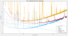
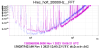
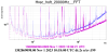
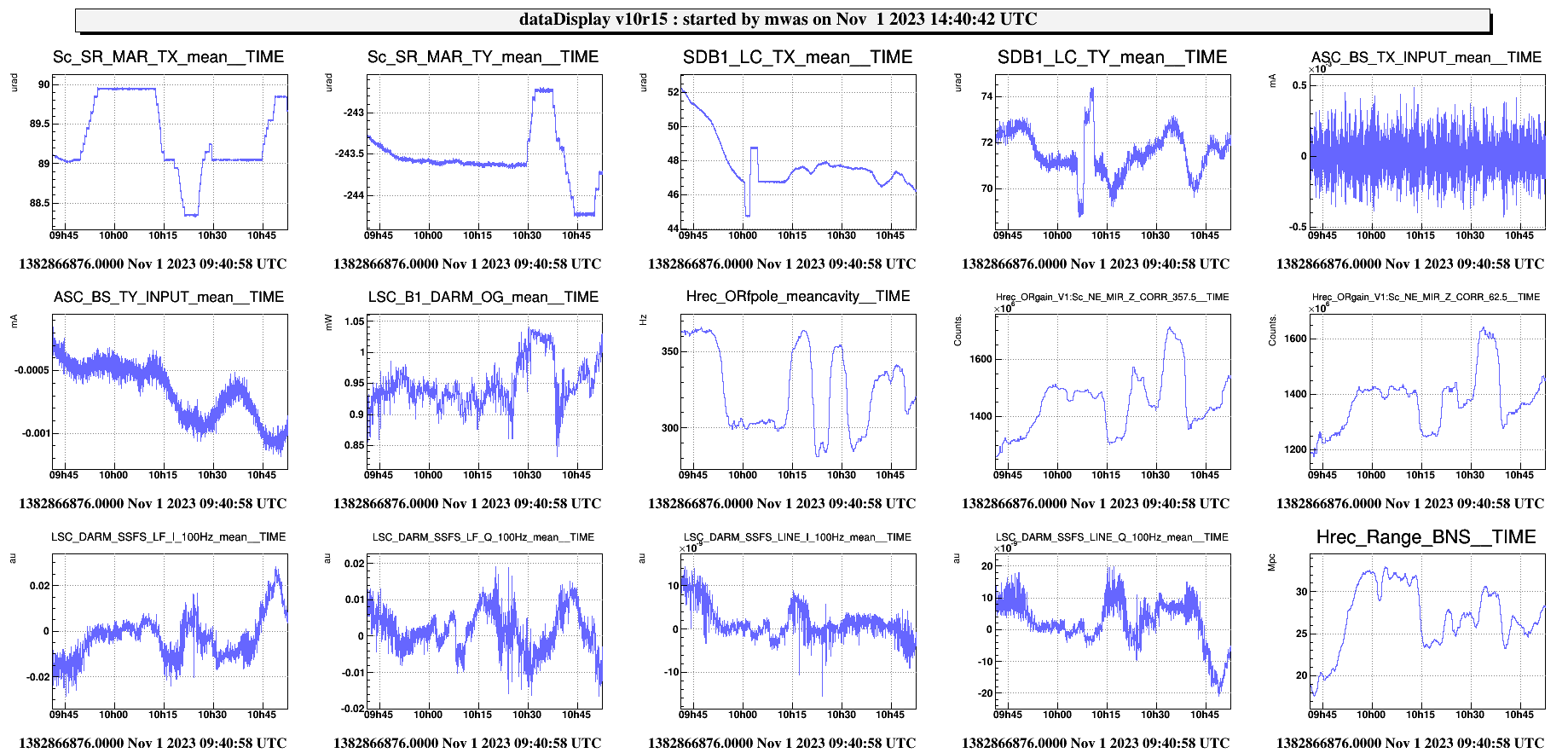
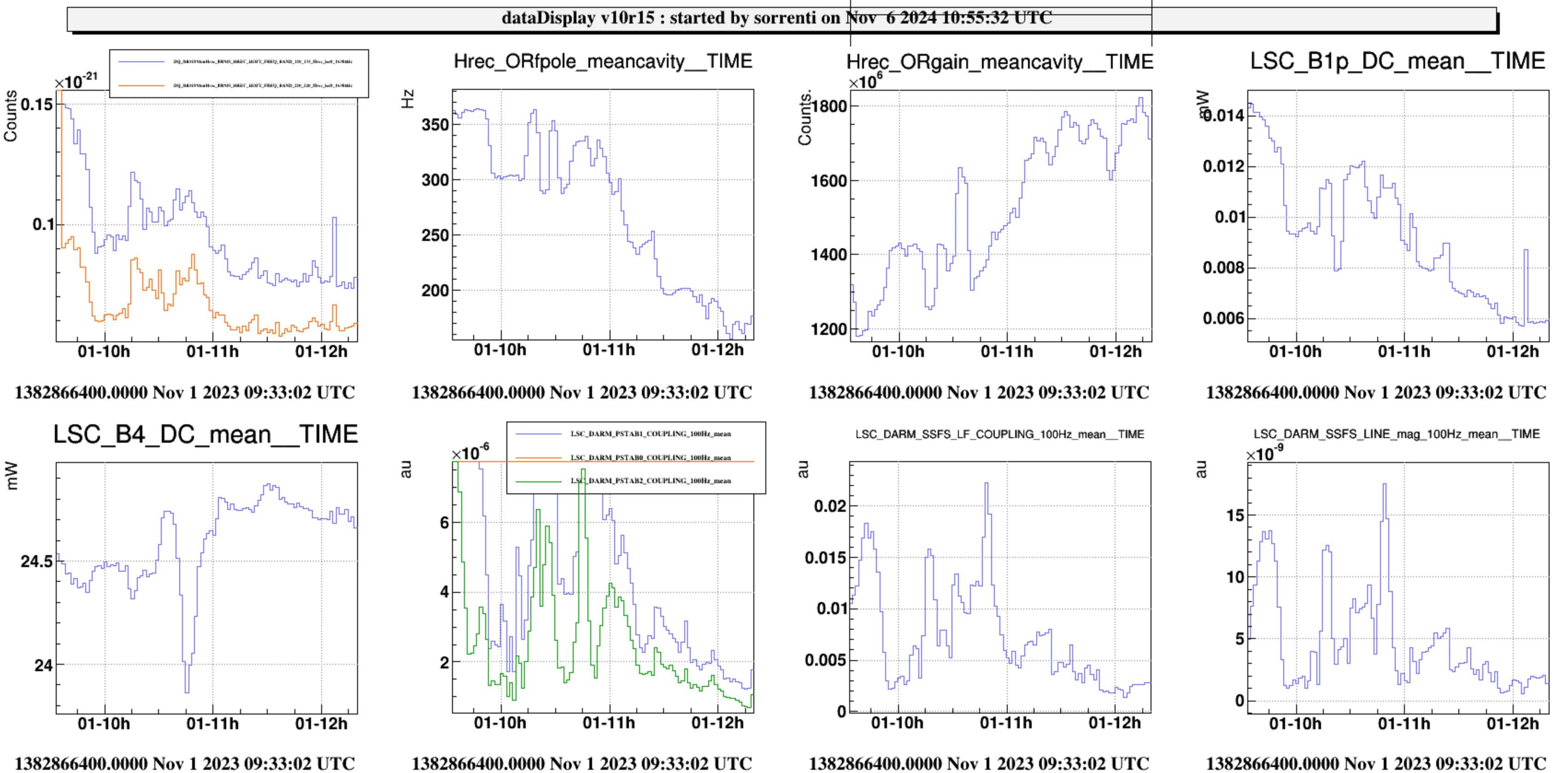
Figure 1 shows the initial exploration. In both direction of SR TX the optical gain increases, in horizontal direction optical gain increases in the postive direction. While in the negative direction it doesn't increase as much and the cavity pole frequency doesn't decrease as much, looking back at the data, the horizontal scan in the positive direction went further than in the negative direction, so this could be the explanation for the difference. In any case SR TY in the negative direction was making the CMRF much worse and was pushing for large BS TY misalignment.
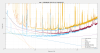
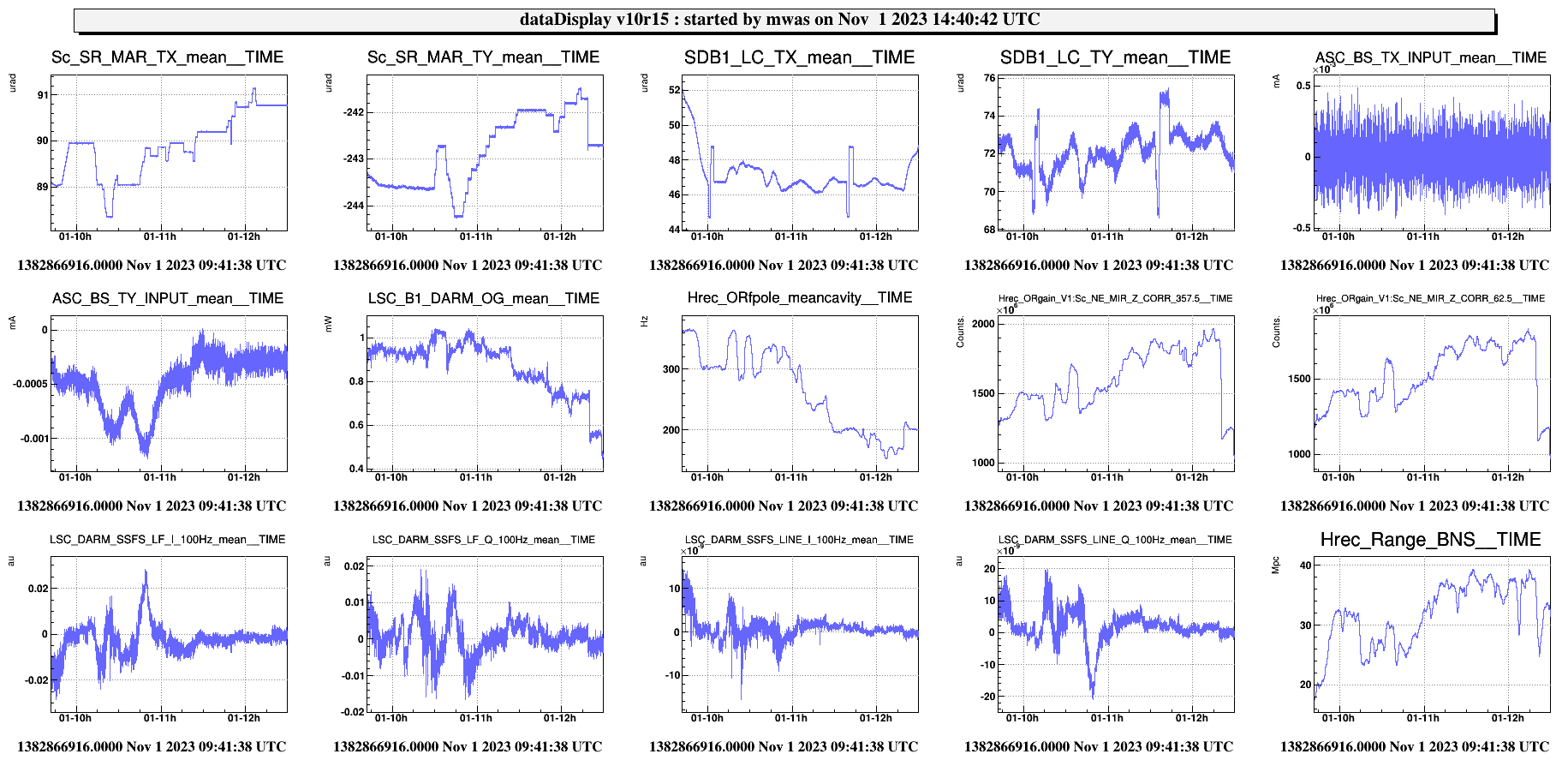
Figure 2 shows the full exploration, that then tried several diagonals. At the end going in SR TY and SR TX in the positive direction looked the best from the BNS range point of view. SR TY was making the CMRF better (so that BS TY misalignment could be reduced), SR TX was making SSFS LF I and LF Q superposed, so that both could be zero at the same time. The low frequency Hrec gain was increased by a factor 1.5 in total, while the SR+arm cavity pole was reduced to 200Hz. Going further in misalignment I started to have large alignment oscillation visible on B1p. I haven't checked but the DARM loop might be strongly affected by the lo frequency of the pole too.
At the end I have started to make reductions of the DARM offset (which made the range worse by a few Mpc). And unlocked while trying to change the SR alignment.
Part 2 - HOM noise
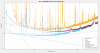
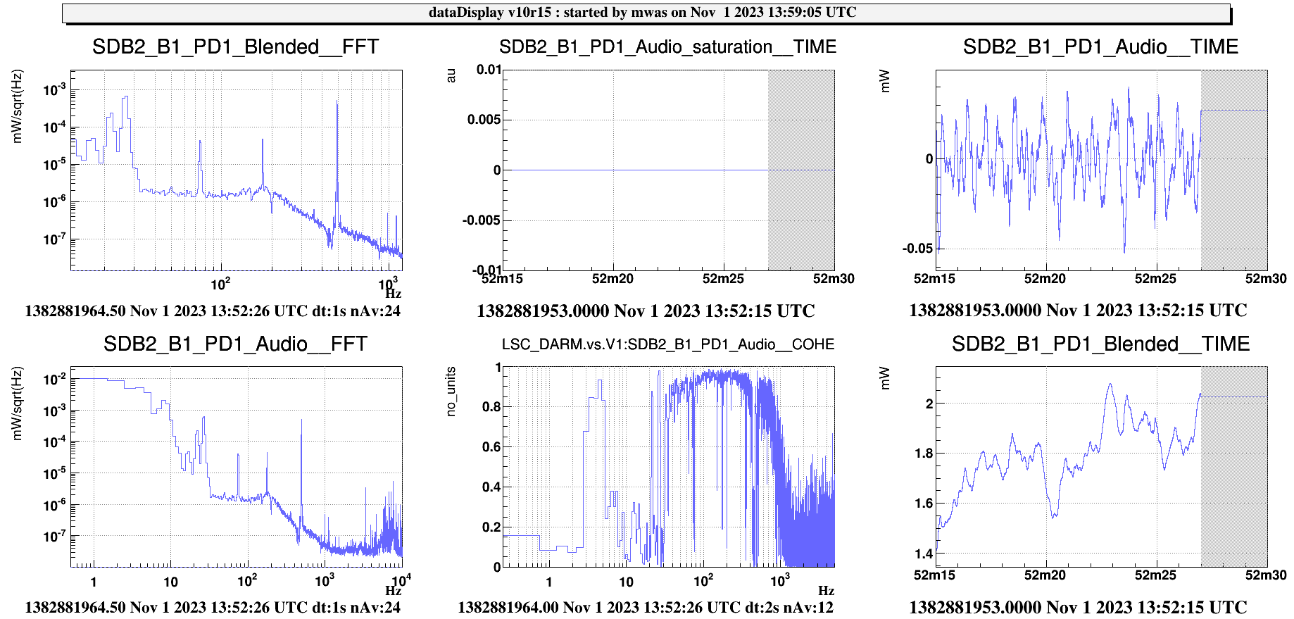
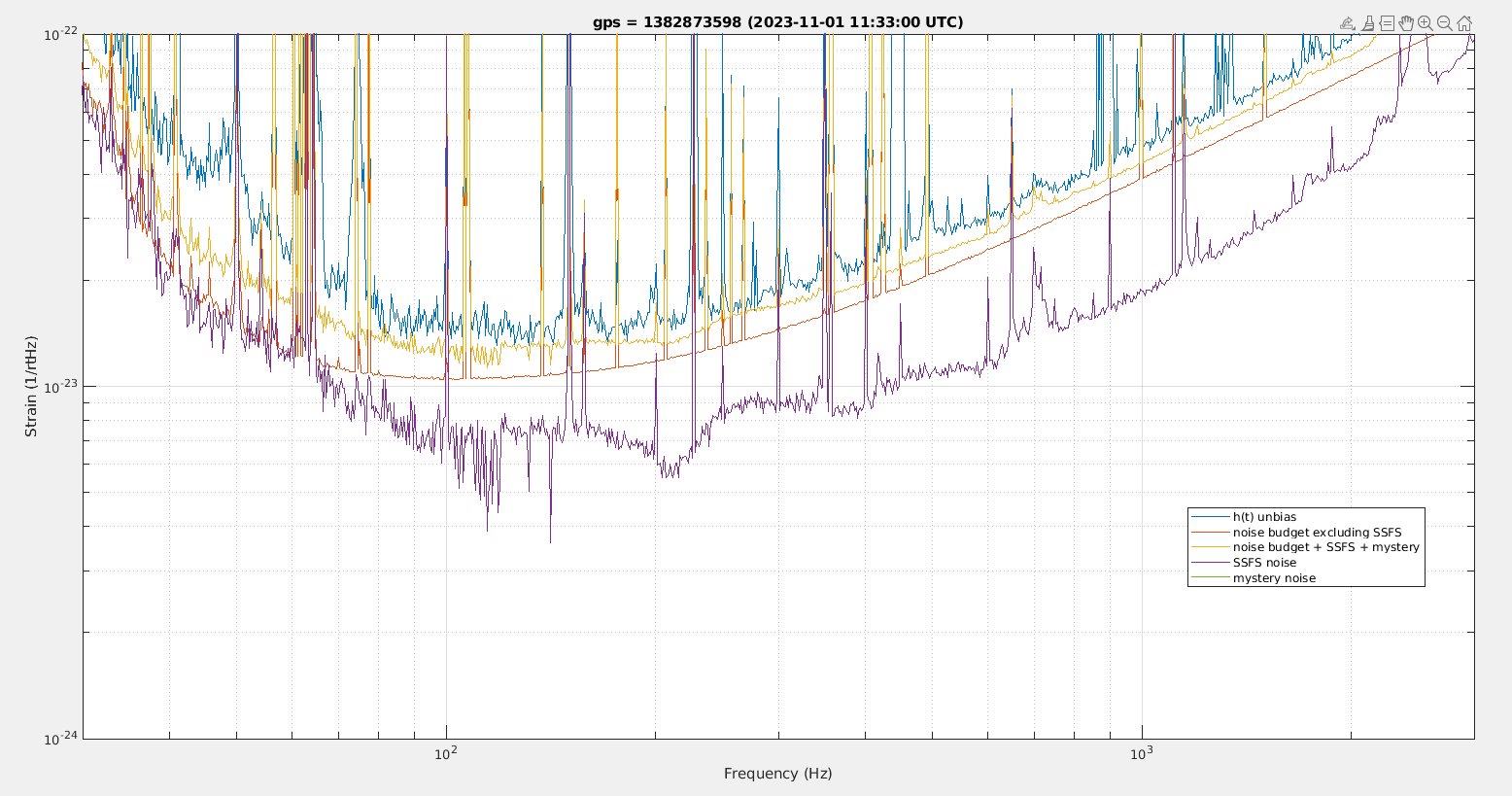
Figure 3 - locking the OMC in CARM NULL on the order 3 mode was most of the time saturating B1 PD1, but managed to get 15s without saturation. The spectrum is dominated by DARM feedback noise.
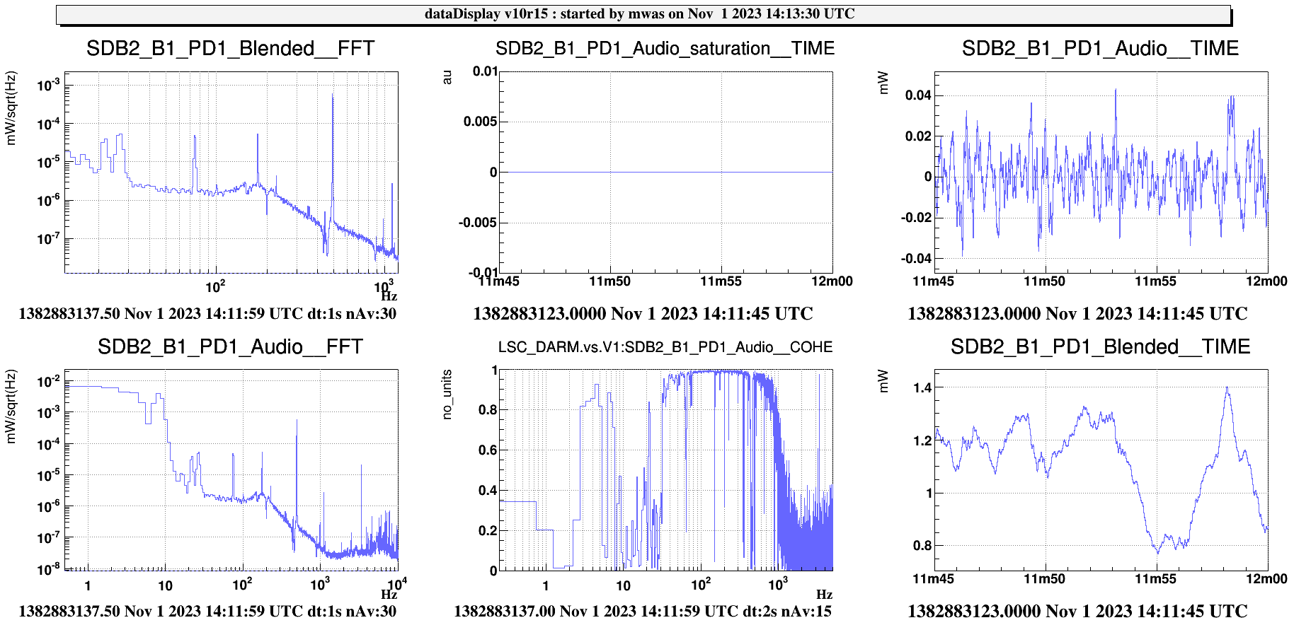
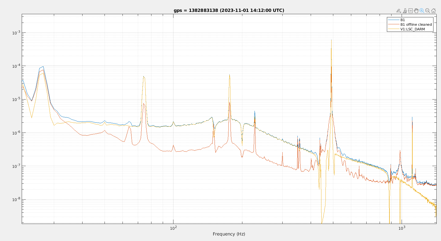
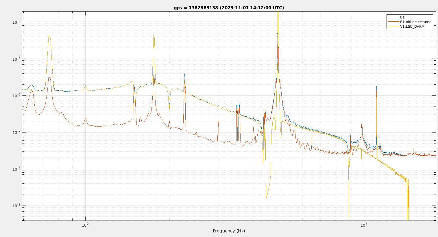
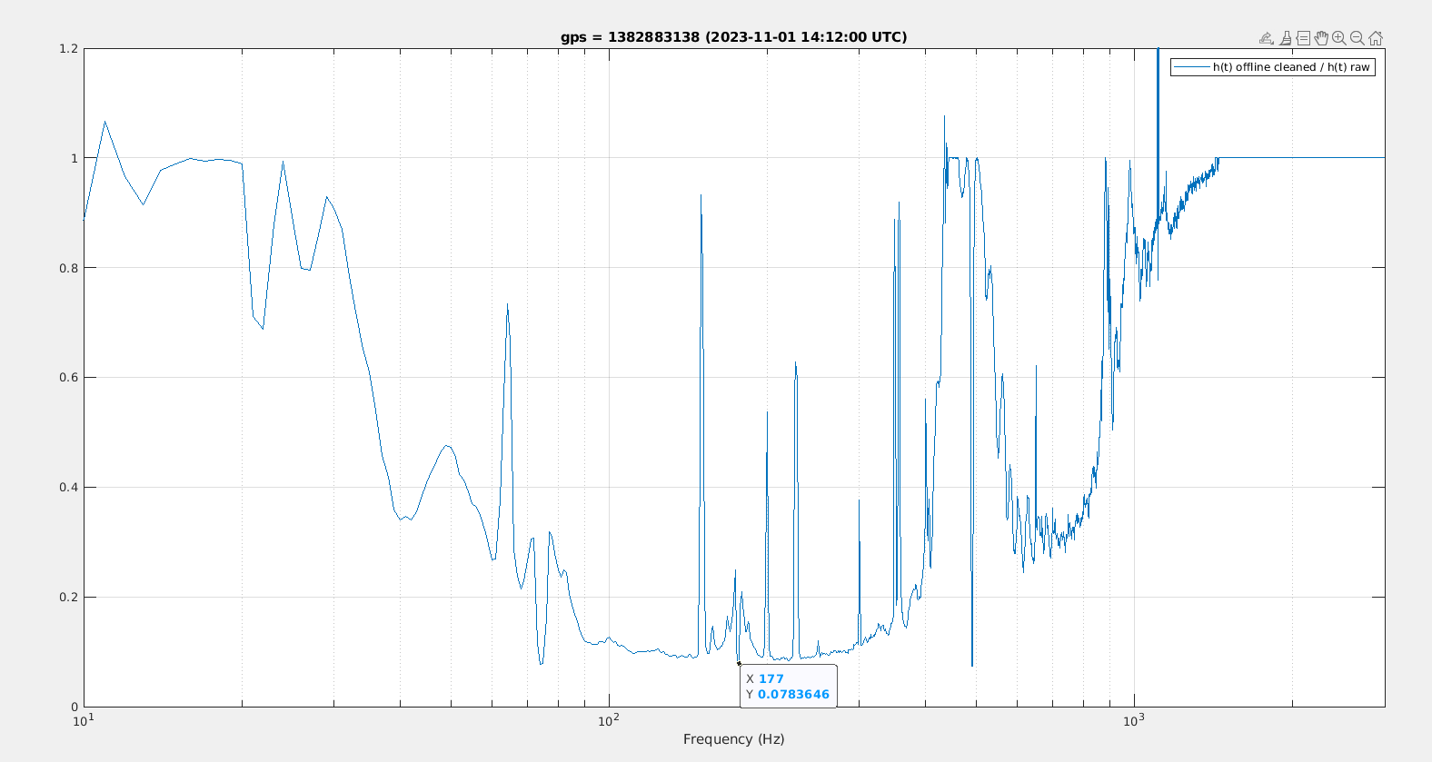
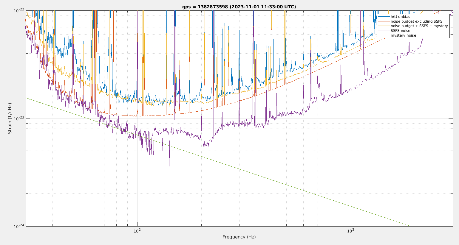
Figure 4 locking on the order 5 mode saturations are only occasional (once every 1 or 2 minute), the spectrum is again dominated by DARM, maybe there is a way to subtract it. There is 10min of data starting at 14:12 UTC.
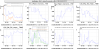
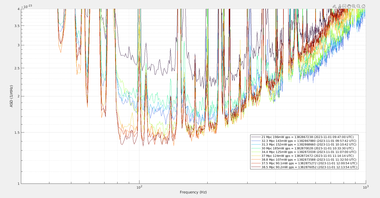
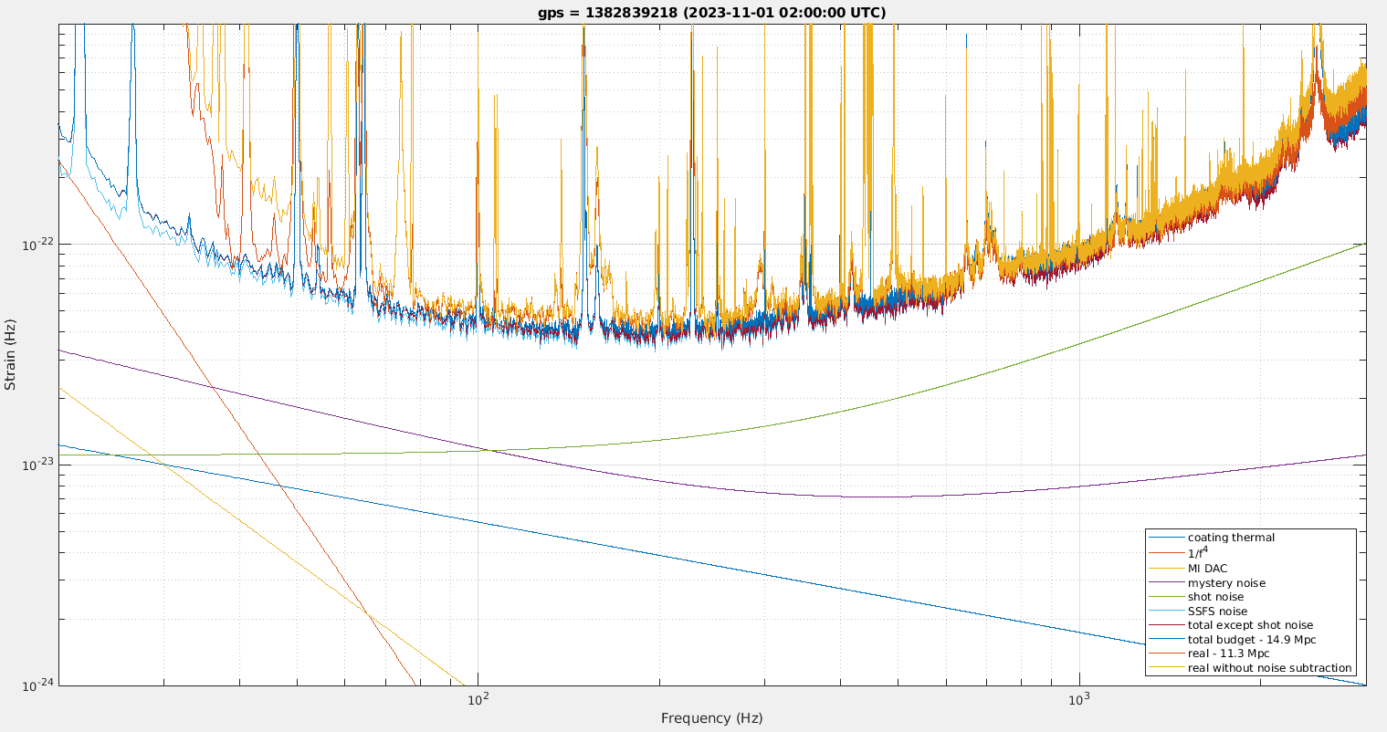
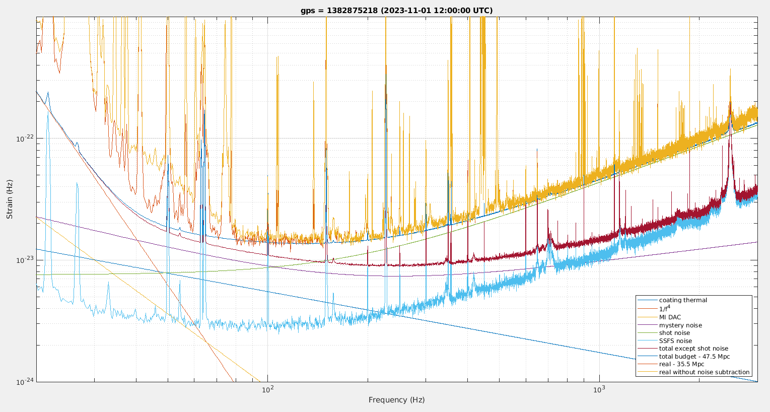
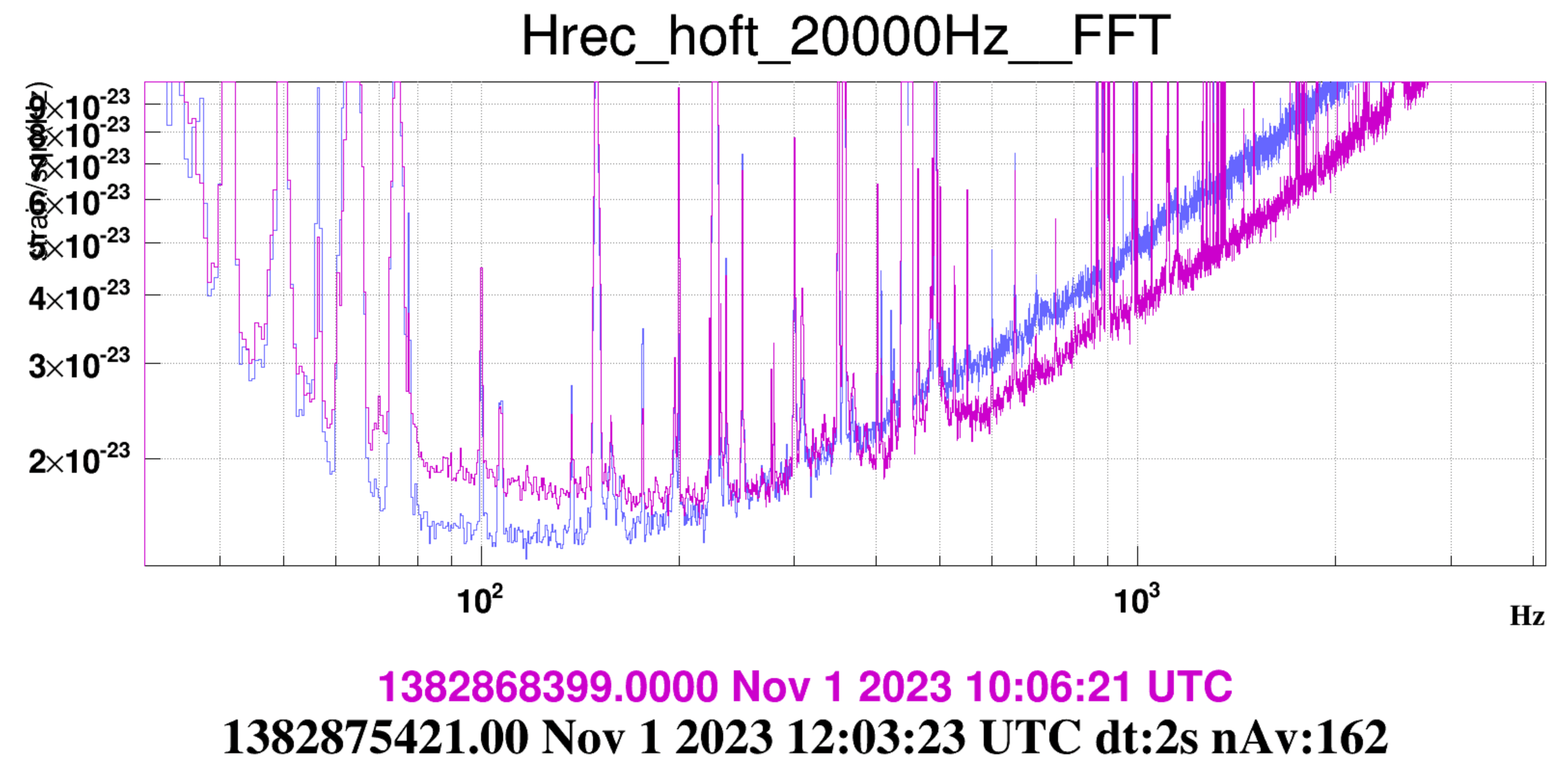
Figure 5 shows the best sensitivity for each 20min of data during this tuning. It is not the best way of analyzing things, but it shows how the sensitivity at 100Hz improves by a factor ~1.5 while the sensitivity at 1kHz gets worse.
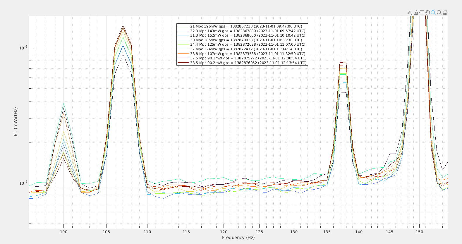
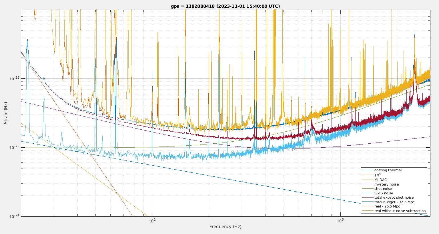
Figure 6 is the same times looking at the B1 spectrum. There are changes of the order of +/-10% of the noise floor during the tuning (and not correlated with the BNS range improvements), what is changing is the height of the calibration lines at 107Hz and 137Hz, which means that the optical gain of the interferometer is increasing while the noise floor stays the same.
This data needs to be further analyzed before trying another shift on HOM noise. There might be no need for another shift on this topic.
Details
Put SRCL_SET_SET to zero (instead of -3.0 in the automation)
9:48 UTC, turned of SR TX AA, MAR TX at 89urad
starting to move SR TX in positive direction, the BS TY loop is still working on zero the CMRF, which increases the DARM optical gain on B1.
9:55 UTC SR TX +0.9urad (4min)
10:00 UTC turing off OMC AA
doing +/-2 urad in SDB1 TX and SDB1 TY, it changes the frequency noise coupling, so CMRF gets worse for each step, and not waiting for it to catch up.
10:11 UTC turning back on OMC AA and remvoing offsets
10:12 starting steps to move SR TX back to initial position
10:15 SR TX (3min) back at initial position, CMRF got worse as BS TY loop slowly misaligns further to compensate, also optical gain 60Hz and 360Hz are worse by ~10%, cavity pole frequency improves by 60Hz
10:21 -0.7urad on SR TX (4min) optical gain 60Hz and 360Hz again increases by ~10%, and arm cavity pole decreases by 60Hz
10:28 turning of SR TY AA, stead state aligned is -243.6 urad
10:33 (4min) +0.9urad on SR TY, SR+arm cavity pole decreases by 60Hz, gain at 60Hz and 360Hz even higher than for TX misalignment
going to negative TY misalignment, arm cavity pole frequency is not really decreasing. But CMRF very bad and BS TY getting far from zero.
10:45 starting moving in SR TX, to improve CMRF
exploring SR alignment towards the positive direction in both TX and TY as that improves the BNS range, reduces the BS TY needed to have SSFS coupling at zero
11:32 UTC turing off OMC AA and making steps in SDB1 alignment
11:44 turned back on OMC AA
SR TX seems to control the separation between SSFS LF I and Q quadratures, increasing SR TX bring LF I up and LF Q down
11:55 (3min) moved SR TY by -0.3 urad, and lost a few Mpc in sensitivity
11:59 (3min) moved SR TY by +0.25urad and got the Mpc back
Hitting a limit with going further in SR misalignment. With angular oscillation and maybe DARM phase margin disappearing as the SR+arm cavity pole is at ~150Hz.
~12:15 starting to reduce DARM offset
At reduced offset to 2mW, unlocked when trying to move SR in TY.
13:19 locked on order 3 mode
12:24 turned off DIFFp UGF servo and lines
12:26 opened B1 PD1 shutter
turned off SR TX/TY line
turned of WI and NE lines, reduces WE and NI line by factor 3
turning off NI line had change the power in the arms by ~5%
reduced BS TY and PR TY line by factor ~2
managed to get 15s of data without saturation, DARM signal is dominating the spectrum
14:10 locked on order 5 mode
14:12 (10min) B1 PD1 open
has occasional saturation, but also clearly dominated by DARM, maybe with enough data the DARM contribution can be removed to have an upper limit on the noise. Will need to go around the saturation that occur every minute or two
closed B1 PD1, went back to lock acquisition and tried to turn back on all the lines and loop that were disabled to take the data on HOM


