Reports 1-1 of 1 Clear search Modify search
Detector Characterisation (Glitches)
mwas, direnzo, dal canton - 21:42 Monday 09 October 2023 (61944) Print this report
Potential lead on ~25min periodic glitches

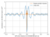
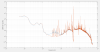
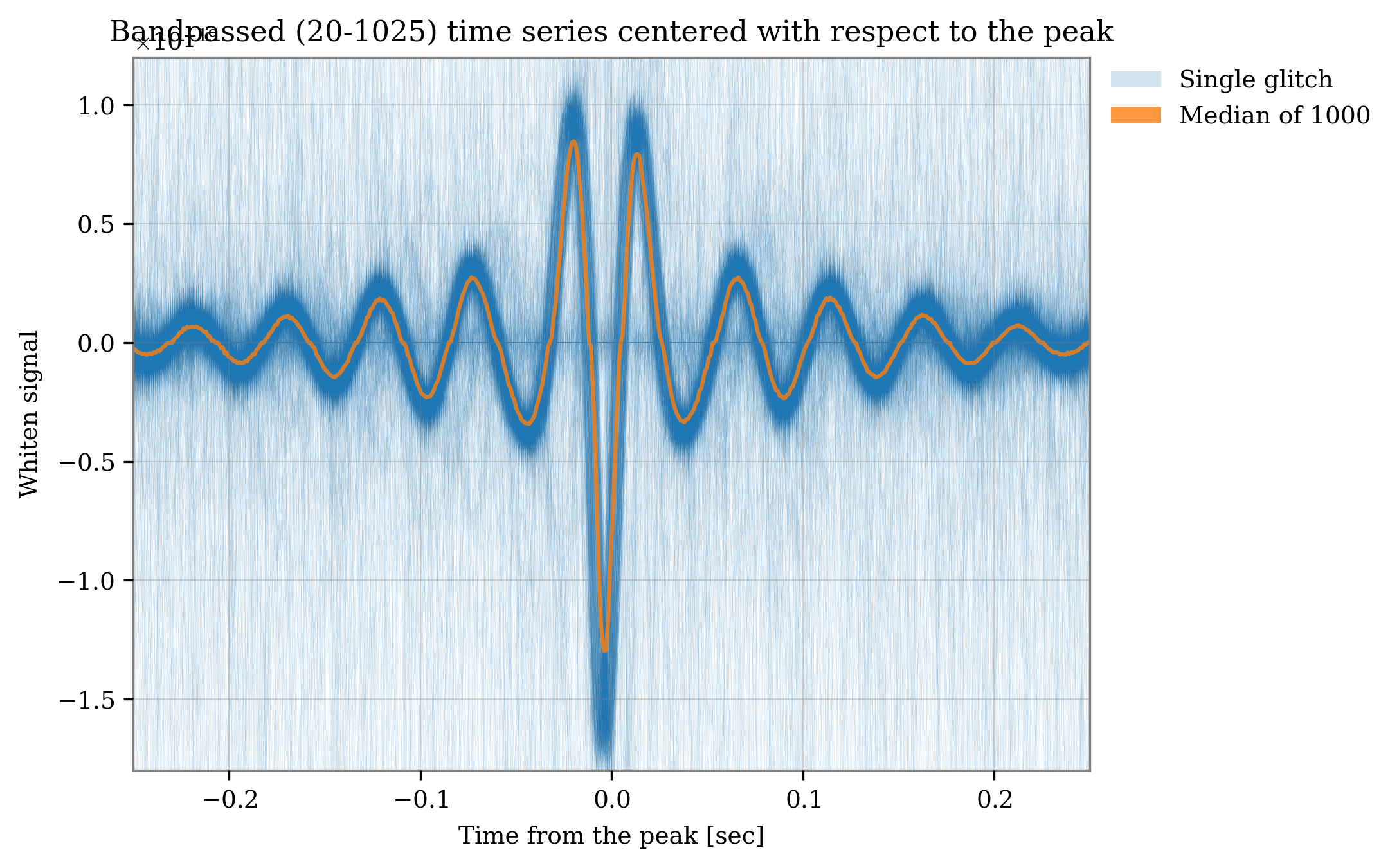
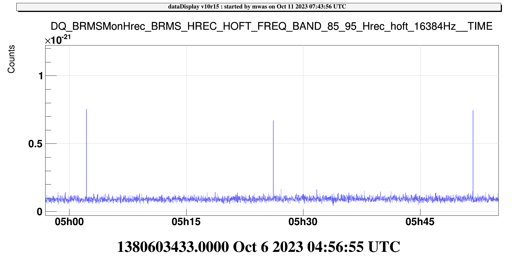
Figure 1 Tito has analyzed some of the glitches seen in h(t) using some whitening filters, they have all the same shape

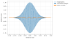
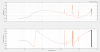
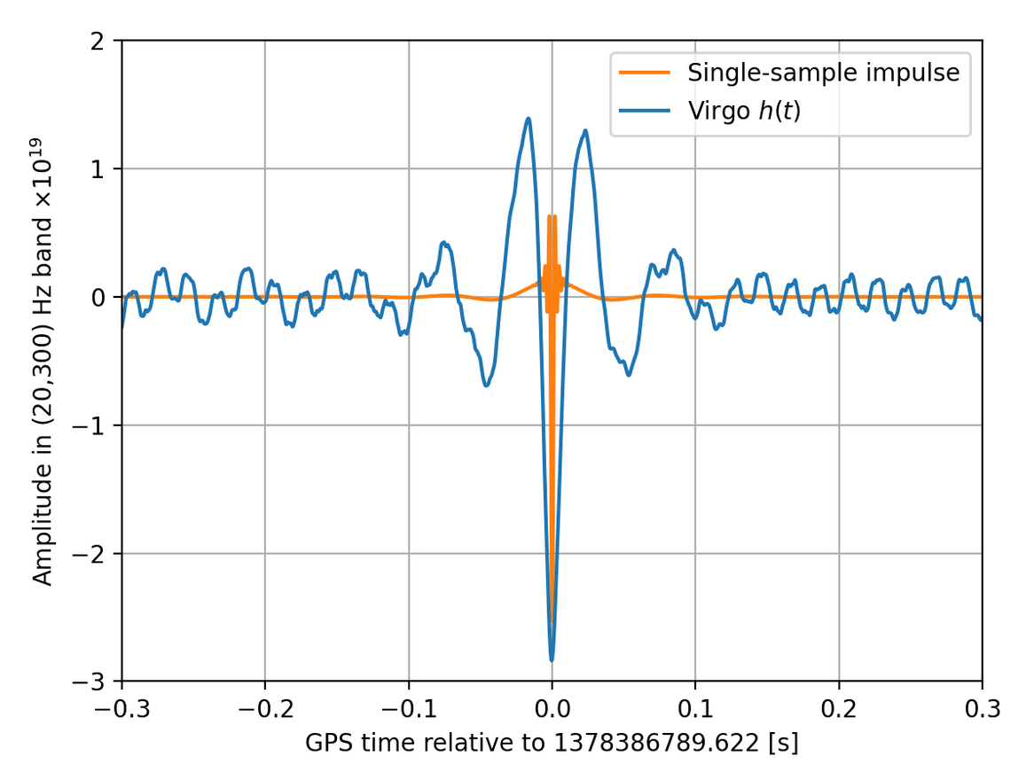
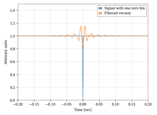
Figure 2 Francesco noticed that a very similar shape can be obtained using a bandpass filter response to one sample long drop from one to zero

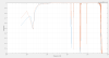
This suggest that it could be a digital control system issue. Comparing the transfer function between two point in a control loop one can determine in which half of the control loop the noise originates from. For example if one looks at the transfer function between a photodiode and the control correction derived from that photodiode, one can find out if the dominant noise is in the control system or in the plant. This was one of the test used to verify that GW150914 was an astrophysical signal and not a malicious hardware injection.

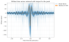
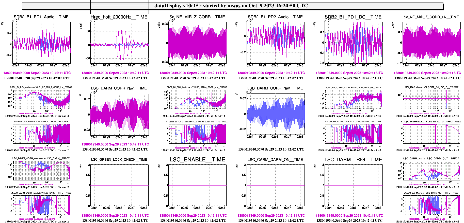
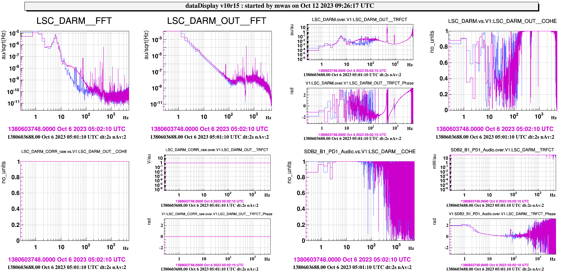
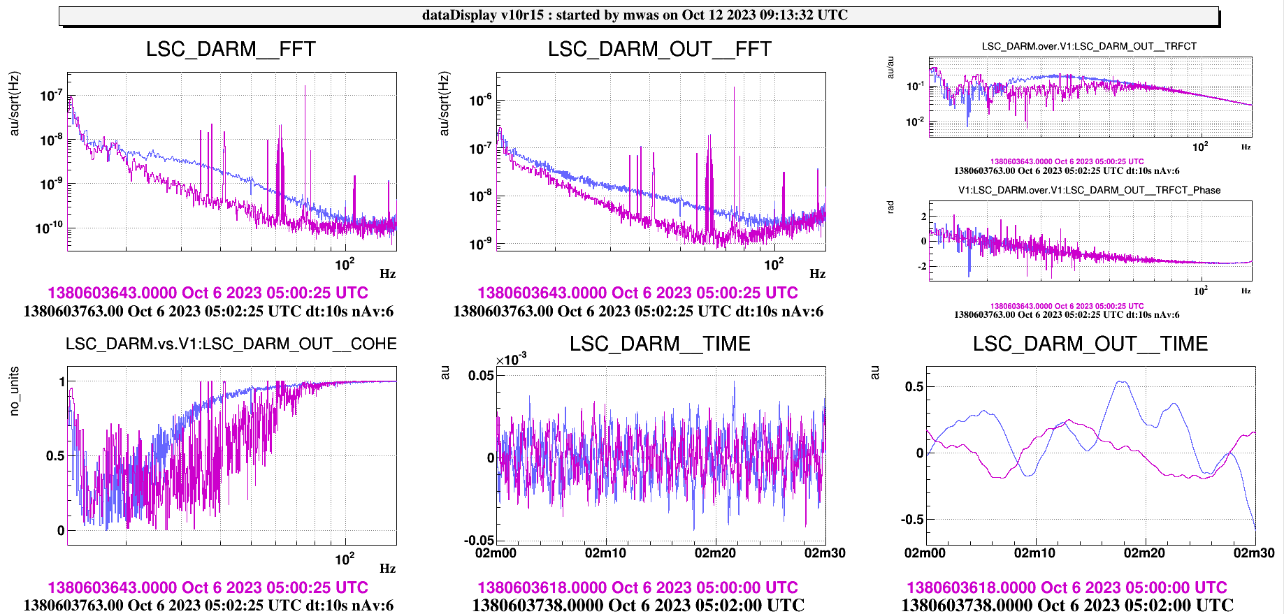
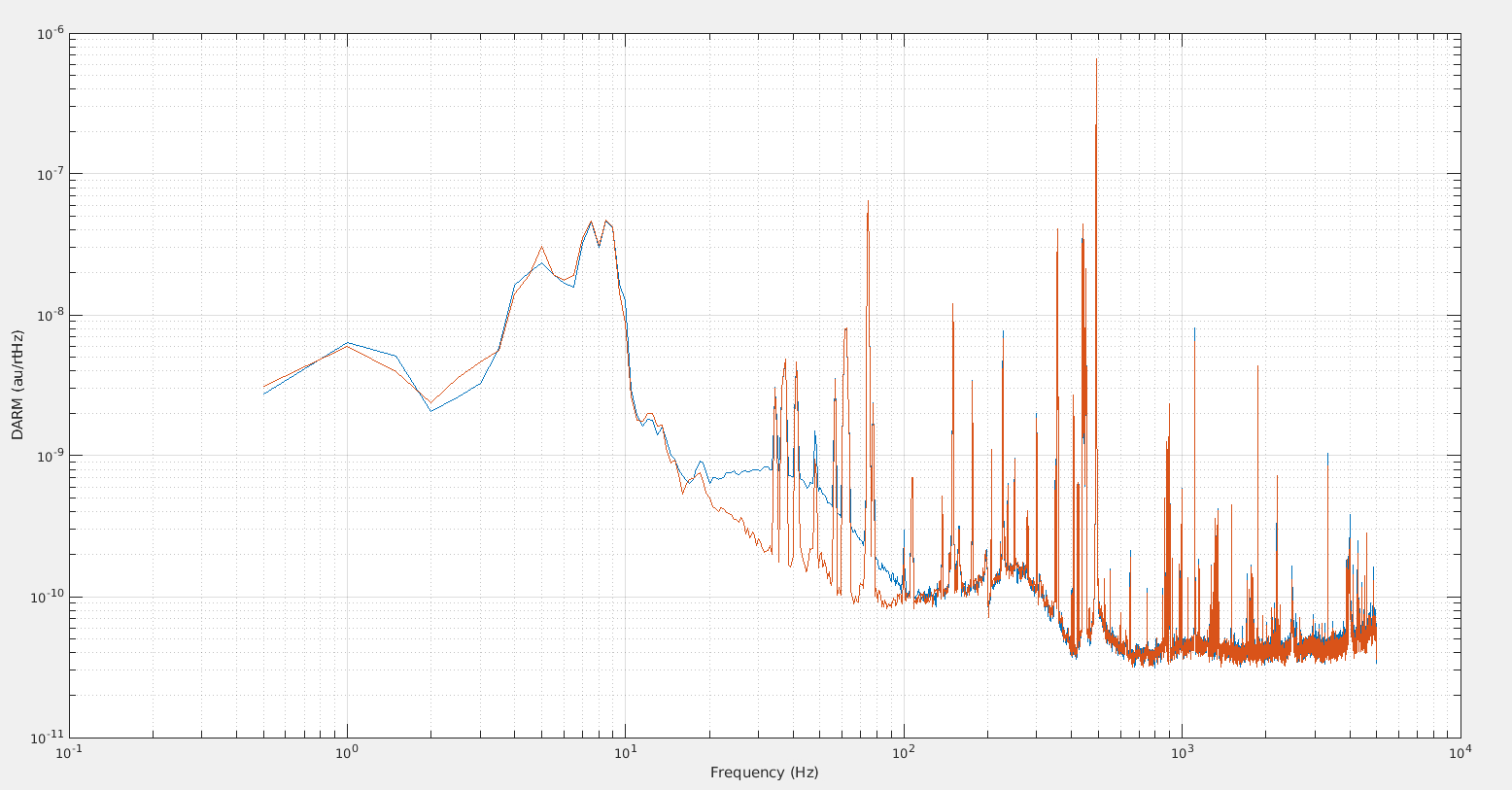
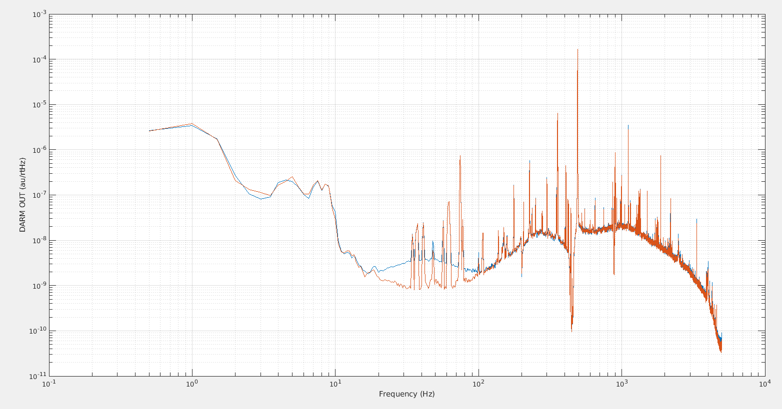
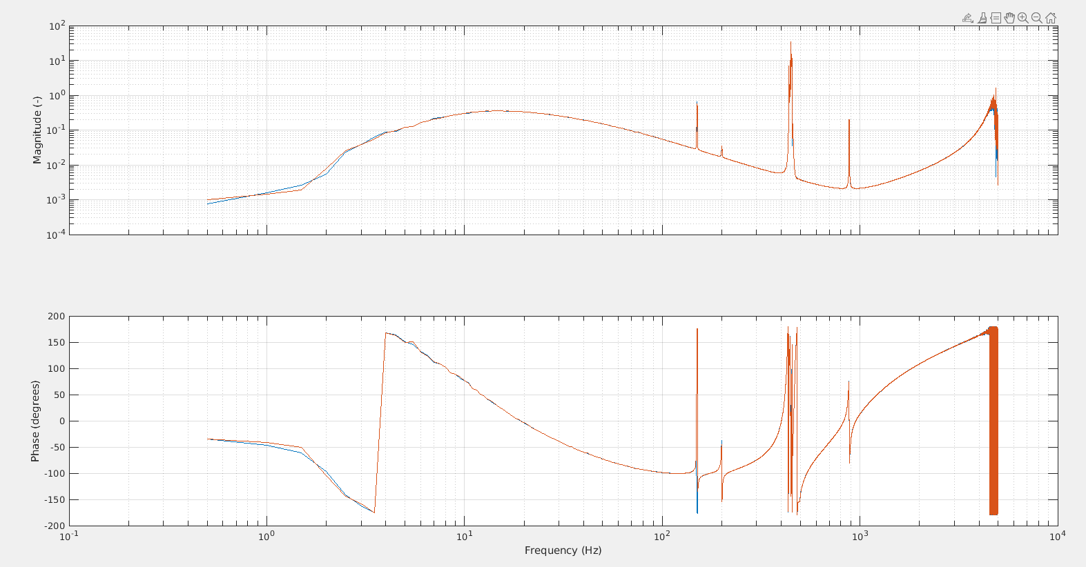
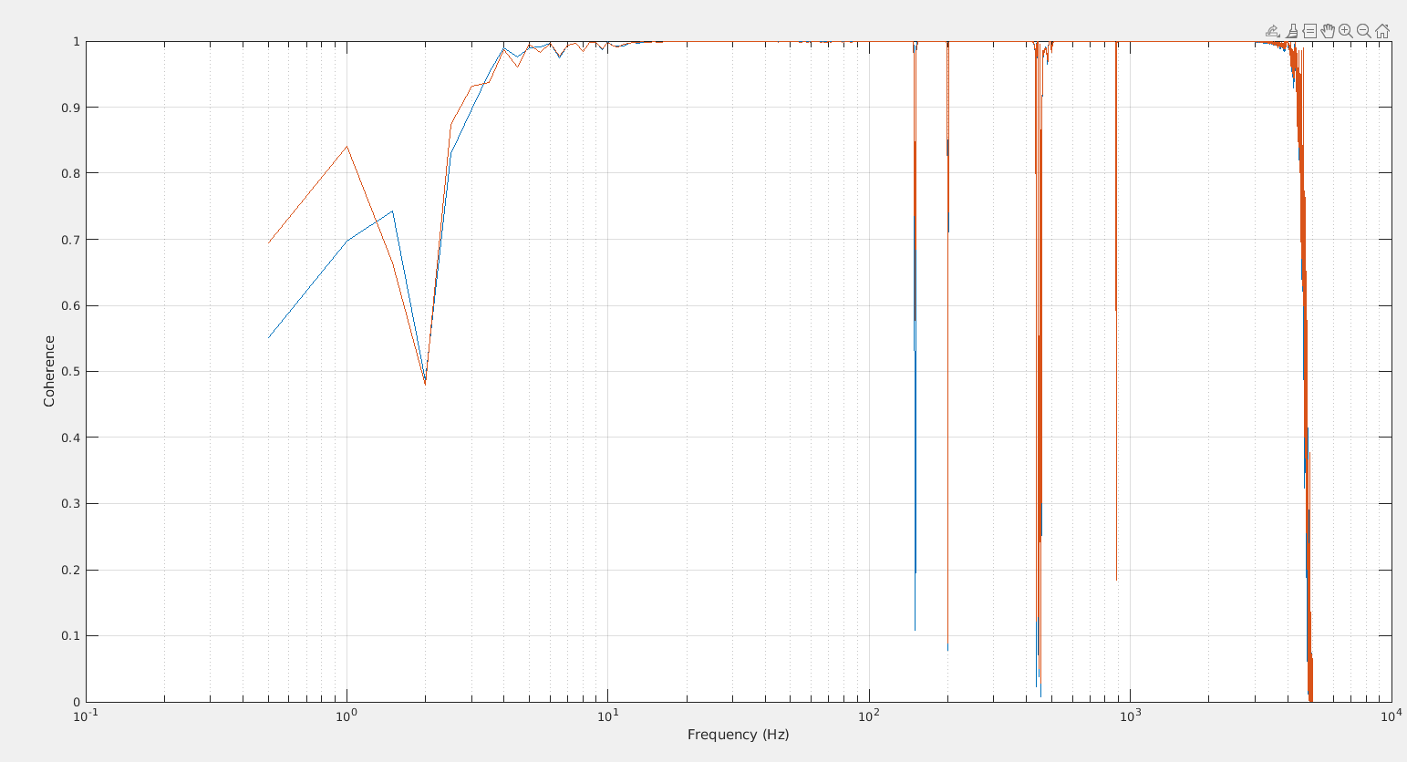
Figure 3 summarizes that train of thought, with in purple 2s of data including one of the glitches, and in blue 2s of data without a glitch. The glitch is clearly visible in the bandpassed h(t) data, the shape is different from figure 1 & 2, presumably becasue the type of filter is different (a causal filter instead of a zero phase one). Looking at the transfer function one can notice that for example the SDB2_B1_DC to LSC_DARM transfer function doesn't change, as expected. But some other transfer functions do change, in particular the LSC_DARM to LSC_DARM_OUT transfer function (bottom right corner) changes shape during the glitch. The only explanation I can find is that the source of the glitch is in between these two channels instead of being inside the interferometer.

This should narrow down the origin of the problem to these 3 lines of Acl code:

ACL_FILTER_CH    DARM_OUT    "au"    1    LSC_FREQ    DARM        1    "LSC_NONE"
ACL_FILTER_CH_OPTION DARM_OUT        -1 "sin_inout" "linear" 0 10 0 50
ACL_FILTER_CH_RESET_CND        DARM_OUT    DARM_TRIG

So either there is a glitch in the computation of the DARM filter or the DARM trigger sets the filter output to zero for a very short time (one sample?) despite being constant equal to one in the data saved by the DAQ.

Images attached to this report
Comments to this report:
dal canton, direnzo, was - 0:54 Tuesday 10 October 2023 (61945) Print this report

Following the initial suggestion by Tito and the push from Michal, I have tried to directly compare the waveforms of multiple occurrences of these glitches by aligning their time series to the peak time of the corresponding omicron triggers. First of all, notice that if their phases had been completely random, averaging these shifted time series would have given zero as a result. For example, in Fig. 1 I have reported the mean (orange line) of 1000 sine-Gaussian signals (represented by the blue lines); their mean is indeed close to zero and the larger the number of averages, the closer. This was my concern too for a similar operation on the glitch time series but, in fact, this has been the discriminating factor in the analysis I'm about to describe.

I have tried to identify the omicron triggers representing the annoying 25-minute periodic glitches by applying the following selection criteria: 35 Hz < peak frequency < 110 Hz, and SNR > 40. I have put the last 1000 omicron triggers matching the previous criteria in the attached CSV file (I had to change the extension to txt but this is in fact a CSV). Notice that the previous criteria are not perfect and the CSV file contains a number of triggers not belonging to this family of glitches.

In Fig. 2 I have plotted, with semitransparent tiny blue lines, the time series of 1000 glitches bandapssed between 20 and 1024 Hz. The darker the color, the larger the superposition of the waveforms. In fact, most of them follow the same exact pattern, that is, they have the same phase. Moreover, all these glitches seem to have very similar SNRs. The orange curve represents their median (not mean to be more resilient to completely different waveforms). Notice also the darker shade in the correspondence of the y = 0 axis. This takes into account all the other glitches, not belonging to the 25-minute family, with random phases and that average to zero.

In order to verify the effects of the lowpass filter, in Fig. 3 I have reported the same analysis as before but with the second corner frequency set to 100 Hz. This and the former figure look in fact very similar, with the former being visually more "furry" (more high frequencies) than the latter, as expected.

As a final check, I repeated the analysis one last time making use of the whitened time series: Fig. 4. There are visible differences at the sides with respect to the previous figures but the main oscillations at the center are still all similar.

This confirms the hypothesis that the sign of these glitches is always the same, possibly reinforcing the claim in the main entry that these are originated by a zeroed sample in some filter output related to DARM.


EDIT:  the y-axis label in Fig. 2 and 3 is wrong. These signals are not whitened and they have strain units (x 10^-19).

Images attached to this comment
Non-image files attached to this comment
mwas - 9:55 Wednesday 11 October 2023 (61964) Print this report

On Oct 16 after 12:16 UTC there was a new DARM filter. The previous one has not changed since 2022. The change of filter seems to have changed the spacing between glitches.

Figure 1 shows 3 glitches during the operation of the new filter, the spacing is ~22min.

Figure 2 shows 3 glitches earlier in the morning, the spacing was wider, ~25min.

So the glitch occurence rate seems to depend on the details pole/zero of the filter used.

Images attached to this comment
mwas - 14:22 Thursday 12 October 2023 (62143) Print this report

Maddalena pointed out that there is a lack of coherence between DARM and DARM_OUT in normal times (without the glitch)

Figure 1 shows that with the short FFT length (2s) I have used to look at only the time of the glitch, the DARM_OUT spectrum has a 1/f^3 spectrum up to 200Hz due to the leakage from the FFT window. So the transfer function is not measured properly.

Figure 2 shows that with longer FFTs (10s) in blue with the glitch and in purple without, the difference between the time and without glitch becomes smaller (and the coherence is still not great)

Figure 3 shows a time without glitch with 100s long FFTs, and then the transfer function and coherence between DARM and DARM OUT becomes good. And there is no visible problem with the DARM filter computation.

Figure 4-7 show that applying a double zero high pass filter at 50Hz for both DARM and DARM_OUT for 30min of data. And comparing 1min with a glitch and 1min without a glitch. Then the glitch is clearly visible in the spectrum with short FFTs (as the dynamic range is reduced by the high pass), and there is no impact on the transfer function and the coherence between DARM and DARM OUT is good in both cases.

In conclusion the ~25min spaced glitches are not related to a problem in the DARM filter computation. This was just a problem in the data analysis due to the high dynamic range of DARM_OUT

/users/mwas/DAQ/DARMfilt_20231012/DARMglitchAnalysis.m

Images attached to this comment
Search Help
×

Warning

Error

The present report has been modified outside this window. Please check for its integrity in the main page.

Refreshing this page will move this report into drafts.

×