Reports 1-1 of 1 Clear search Modify search
AdV-SGD (FDS commissioning)
YuhangZhao, MarcoVardaro - 22:50 Tuesday 27 June 2023 (60706) Print this report
New matrixes are implemented for dithering calibration and actuation

New matrixes are implemented for the dithering loop of filter cavity. This is done from UTC 15:37:00 to 16:28:00

The new loop should be able to tell more precisely the relation between mirror angle change and the voltage we apply on M5 and M7. Follow up analysis will be done to examine this.

Some preliminary test has been done to check the calibration, the UTC time for this check was 17:58:00. From the real-time data, it seems the calibration is roughly fine now. But there will be more detailed analysis in the next days.

Comments to this report:
Zhao - 20:16 Thursday 03 August 2023 (61108) Print this report

The new calibration matrix has been tested today. The work started from 15:02, 03, Aug, 2023 UTC. Two SQZ automation was put in pause.

For the test of calibration matrix, GR_AA and BPC2 were opened. The test was done between 15:10 and 15:30.

For the measurement of actuation matrix, only BPC2 was open. Only GR_M5_X, GR_M5_Y, and GR_M7_X were tuned between 15:30 and 16:00. (Due to some unlock of FC)

Before left EGO, the system was recovered to automation exec.

The GR_M7_Y was tuned between 17:40 and 18:02.

After all these work. The filter cavity is put back to automation exec. 


Zhao, Magazzu, Vardaro - 20:51 Monday 07 August 2023 (61158) Print this report

I arrived this morning and found that filter cavity is misaligned. After some investigation with Magazzu and Vardaro, we conclude that the problem is due to that filter cavity was not locked for a long time and suspended mirrors drift too much away from the good position. The IR beam was put away but brought back by Vardaro so that we can do some test.

The new cal matrix was tested on 4th Aug (logbook is here). This test result is shown in Figure.1. We can see that all the tilts we introduce for filter cavity mirrors can be sensed with good calibration now. We could estimate the error of this sensing but will be done at a later stage.

The new act matrix is measured on 4th Aug (logbook is here). After some calculation based on Figure.2, I implemented the new matrix here (line 68-74). The implementation of the new matrix requires the restart of AFC process, which requires the update of setpoints in the vpm. The details of updating set points are summarized in the attached note. In attached Figure.3, we see the situation of several channels at the moment when AFC process was stopped and recovered. We can see that all channels are brought back to original points and I also put automation back to exec after this operation.

Note that I tried to test the fast shutter for closing SQZ towards FC, but I fotgot to stop automation. This problem was pointed out by Vardaro and summarized in the attached note as well.

The test of new act matrix will be done in the next days.


Images attached to this comment
Non-image files attached to this comment
Zhao, Guo - 11:48 Thursday 10 August 2023 (61211) Print this report

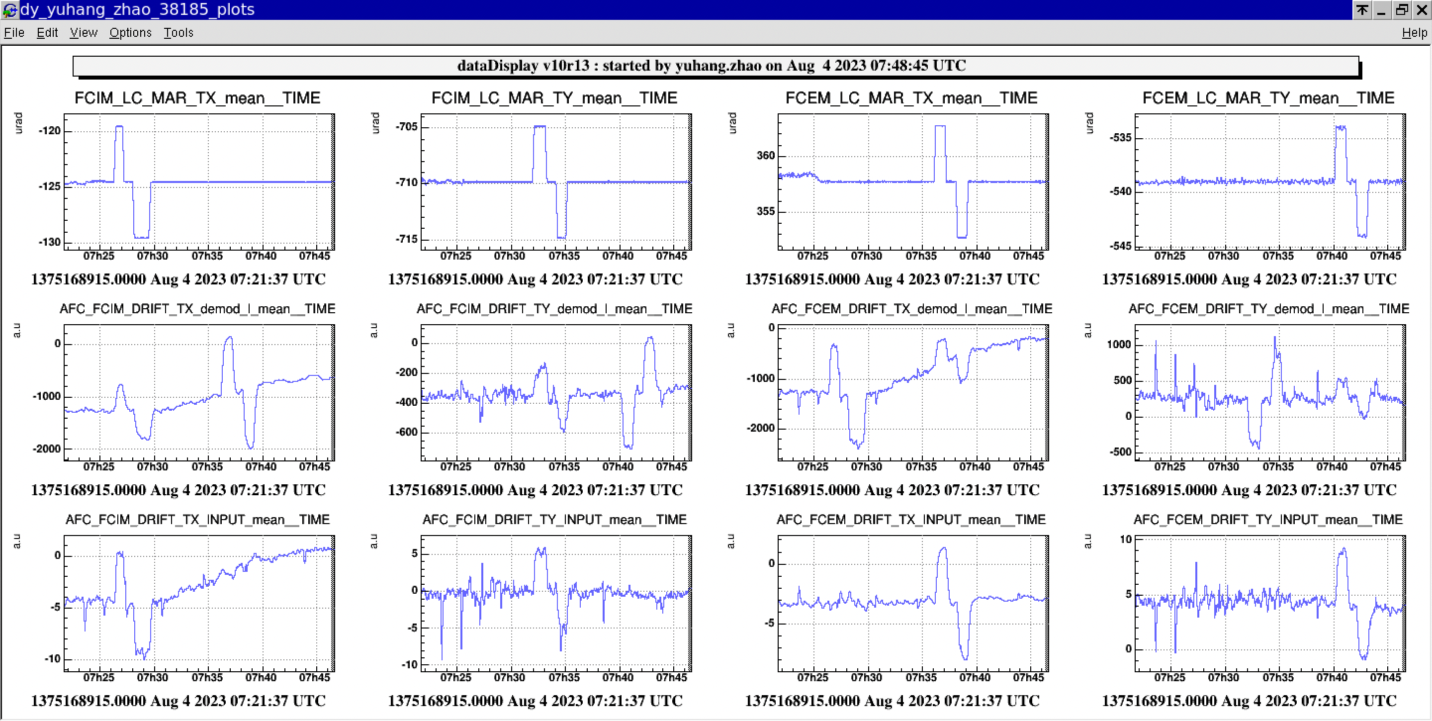
The precision of the dirthering control loop is characterized using the period when the filter cavity is continuously locked. The GPS is 1375487418.0, and duration is 3600 seconds. In this period, the precision is estimated from channels 'AFC_FCI/EM_DRIFT_TX/Y_INPUT_mean', their values (the standard deviation value) are as following

  Input TX Input TY End TX End TY
precision [urad] 0.22 0.62 0.15 0.61

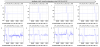
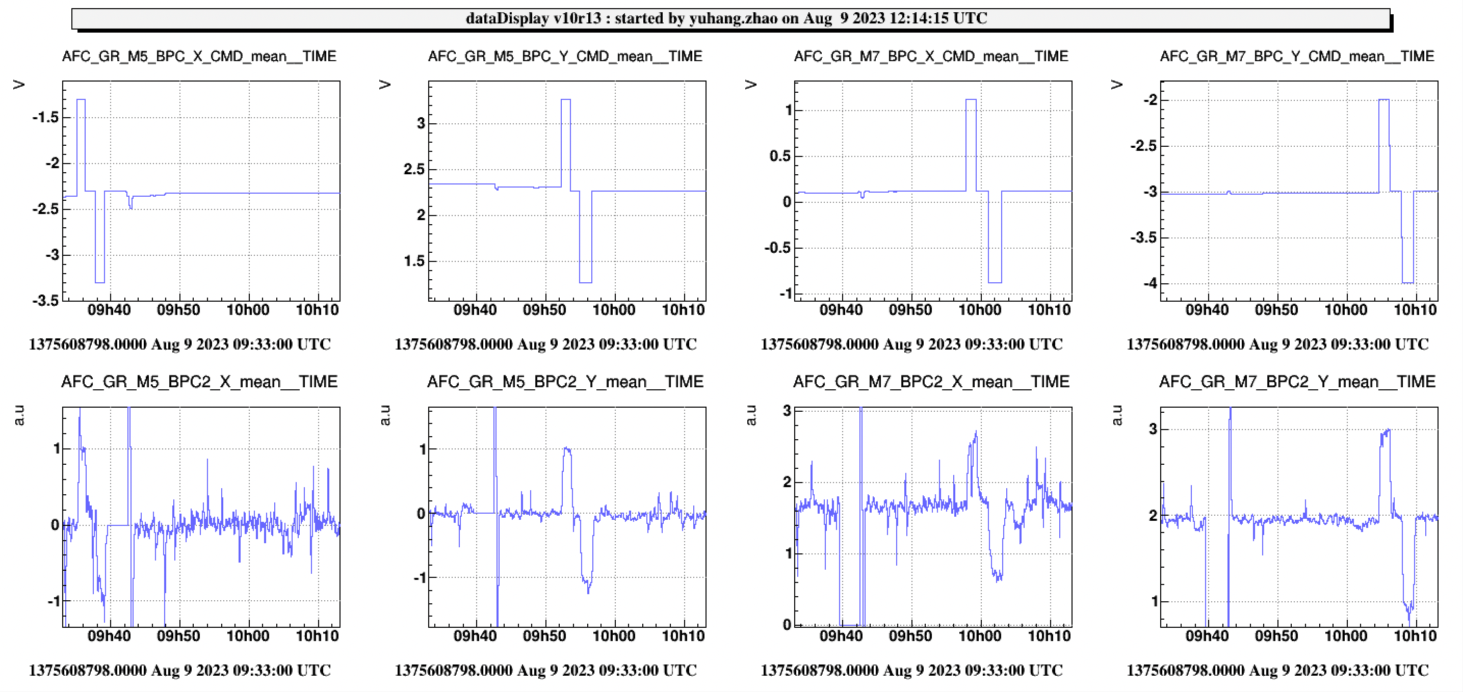
The new act matrix is implemented on 7th August (logbook is here). Yesterday, this matrix is tested. The method of testing this matrix can be found here. As we can see from the attached Fig.1, the amount of M5/7 mirror tilt is sensed by AFC_GR_M5/7_BPC2_X/Y channels with good calibration.

After confirming these calibration, I made calculation here (can be accessed with LSC members). Due to these proper calbration, we know that we could scan mirror with range +/- 9mm from the center of the mirror, assuming that M5/7 mirror original voltage is 0V. The limitation is given by the +/- 9V limitation, which is the maximum voltage we could send to M5/7.

Note that during this work, we found that there was an offset in the BPC2 loop. After confirming with Yuefan, we realize that this offset in the BPC2 loop is set to have the desirable beam position when we use the PSD in the transmission of the filter cavity. However, since we are not using PSD anymore, this offset we are using doesn't make sense for the alignment control.


Images attached to this comment
Search Help
×

Warning

Error

The present report has been modified outside this window. Please check for its integrity in the main page.

Refreshing this page will move this report into drafts.

×