Beam scan methodology investigation
The scan of the beam position inside the filter cavity relies on the offset we put in the dithering loop. The offset we will give has been calculated in terms of mirror tilt angles. However, we realize that the offset (or called set point) is, in fact, put to the acutation on the two green steering mirrors (M5 and M7) in front of the filter cavity (described from line 80 here: /virgoData/VirgoOnline/AFC_GR_pointing.cfg). We thought two ways to surpass this issue: calibrate mirror tilt to acutation on M5/M7 or modify the control loop configuration. After checking that the calibrated dithering error signal (described from line 70 here: /virgoData/VirgoOnline/AFC_GR_drift_ctrl.cfg), we decide we will not modify the control loop configuration. So we will calibrate from mirror tilt to autuation on M5/M7.
Calibrate from mirror tilt to actuation in the dithering control loop
As described in the previous section, there are two steps from mirror tilt to acutation: Matrix_calibrate (demodulated dithering signal to calibrated mirror tilt), Matrix_actuation (demodulated dithering signal to actuation on M5/M7). So to go from 'mirror tilt' to 'actuation', we do 'actuation' = Matrix_actuation * Matrix_calibrate.inv * 'mirror tilt'. While doing the calculation, we noticed that the input/output vectors for above Matrix are not having the same sequence, this should be paid attention also in the future. (such as: input_tx, input_ty, end_tx, end_ty for one case, and input_tx, end_tx, input_ty, end_ty for the other case)
After realizing the calibration of desriable mirror tilt to actuation, we tried in the python script to move manually the M5/M7. However, we found that we want to move end_tx by 3 urad, but we got end_tx moved -6urad. Later on, we found that the negative sign is due to the set point has a negative sign when it is summed to the control loop. And the larger value may come from a wrong calibration. It was realized that the last calibration was done almost two years ago. So we did again the calibration of the two Matrix.
Measurement of the Matrix_calibration and Matrix_actuation
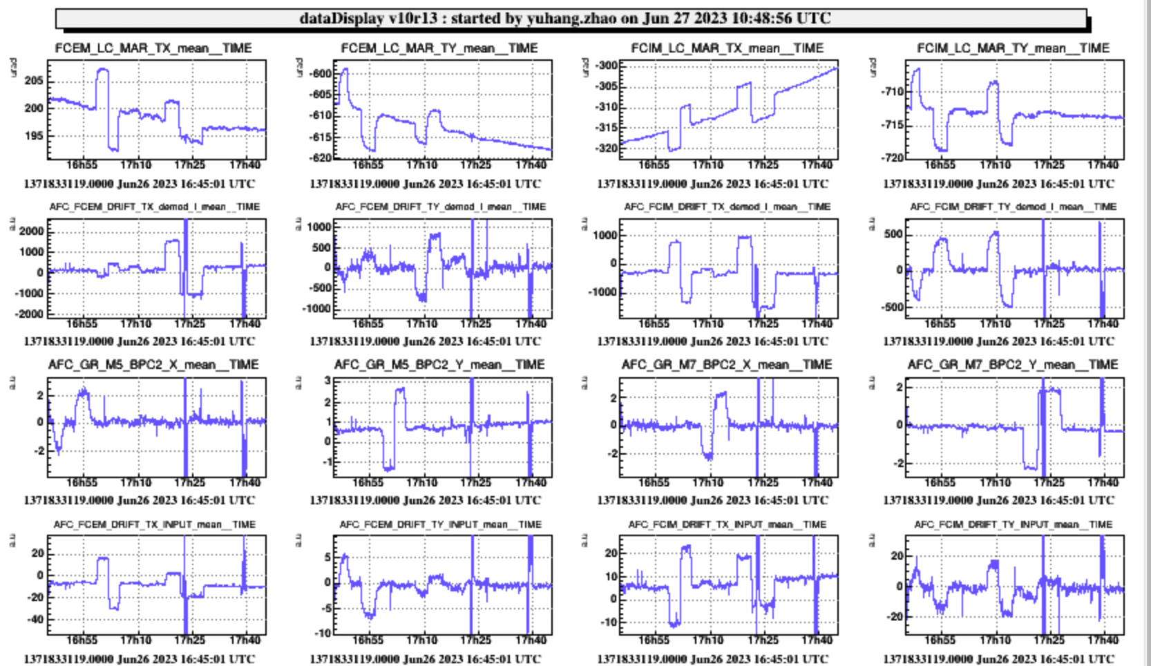
For the Matrix_calibration, we opened the IR AA loop, opened the IR pointing loop, opened the automation PySQZ_IR loop. Then we used SQZ/fcUI moved the oplev with a step of 5urad (this 5urad is calibrated). Then we checked the AFC_FCI/EM_DRIFT_TX/Y_demod_I (starting from UTC 14:48:00 for FCIM, and UTC 15:25:00 for FCEM). We will check later the trend data to calculate matrix.
For the Matrix_actuation, we closed the IR AA loop, opened the IR pointing loop, opened the automation PySQZ_IR loop. I made some mistake at the beginning. It's import to keep IR AA loop closed while the pointing loop open. Then we checked the AFC_FCI/EM_DRIFT_TX/Y_demod_I (starting from UTC 16:45:00 for FCIM and FCEM). We will check later the trend data to calculate matrix.
Measurement of RTL at the center of mirror and the operation point in the past year
We noticed the filter cavity transmission variation due to the operation point change. So we performed some RTL measurements. These measurements are also prepatation for the writting of the automatic code. We will post the analysis of these results later. (UTC 17:38:00 for center, UTC 18:05:00 for the usual operation point)
Next step: Put operation point to the farthest alignment condition (such as 15mm upper, 15 mm left) to check if the range of tilt actuators are large enough. Write the script to make automatic RTL measurements.
The system is put to automation node 'FLT_IR_AA_FMODERR_TUNED' state 'EXEC' at the end of the shift.