The main goal of this afternoon shift was to study the impact of the SDB1/OMC alignment on the sensitivity. Before starting this activity, we made a quick test of increasing the modulation depth of the 8 MHz side band in Low Noise 1.
1/ 8 MHz modulation depth increase:
Triggered by an observation made by Michal this morning ( https://logbook.virgo-gw.eu/virgo/?r=59911 ) we took some data with the 8 MHz modulation depth increased.
Initial setting of 8MHz modulation depth : 9dBm
8 MHz at 10 dBm, at 14h14m35 utc.
8 MHz at 11 dBm, at 14h18m10 utc.
8 MHz at 12 dBm, at 14h20m53 utc. Collecting data for 10 min.
8 MHz at 11 dBm, at 14h31m38 utc.
8 MHz at 10 dBm, at 14h33m41 utc.
8 MHz at 9 dBm, at 14h36m28 utc. Collecting data for 8 min.
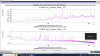
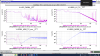
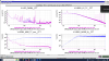
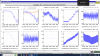
The impact of the 8 MHz modulation depth increase on the SSFS error signal quadrature is shown on Fig.1. (purple with 12dBm, blue with 9dBm). A detailed analysis has been posted by Michal under: https://logbook.virgo-gw.eu/virgo/?r=59915
2/ OMC-SDB1 alignment versus sensitivity
16h50-52 utc: swapping the error signal of SR AA to B1p_DCP (after increasing the DARM_HF_LINE_AMPL at 4e-5).
MICH_SET loop opened at 14h55 utc.
Misaligning SDB1 by adding offset in B1s QD2 RF horizontal error signal (initial offfset is 0 for horizontal signal).
scanning horizontal offset :
15h01m52 UTC +0.001
15h04m03 UTC +0.004
15h07m55 UTC +0.008
15h12m25 UTC +0.016
15h17m35 UTC +0.024
Adjusting B1s camera integration time at 15h21 utc to avoid saturation.
15h27m08 UTC +0.032
15h30m41 UTC +0.037
15h33m45 UTC +0.042
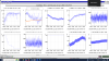
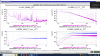
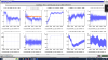
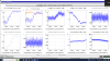
The TY scan of SDB1 is shown in Fig.2. We moved the bench by about 7 urad in TY. There is a cross coupling with TX which changed by 2-3 urad. We have reduced the optical gain by order of 10% and clearly worsened the CMRF.
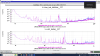
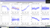
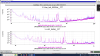
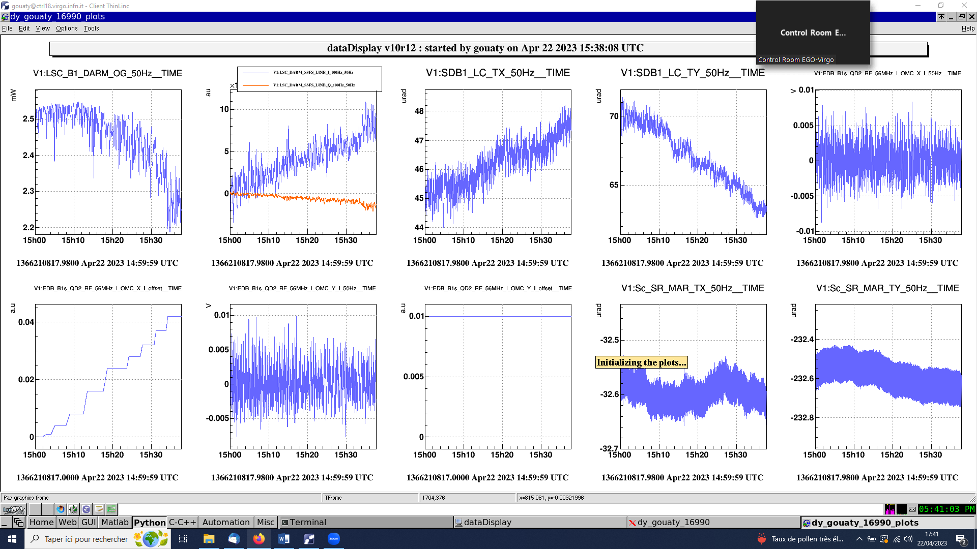
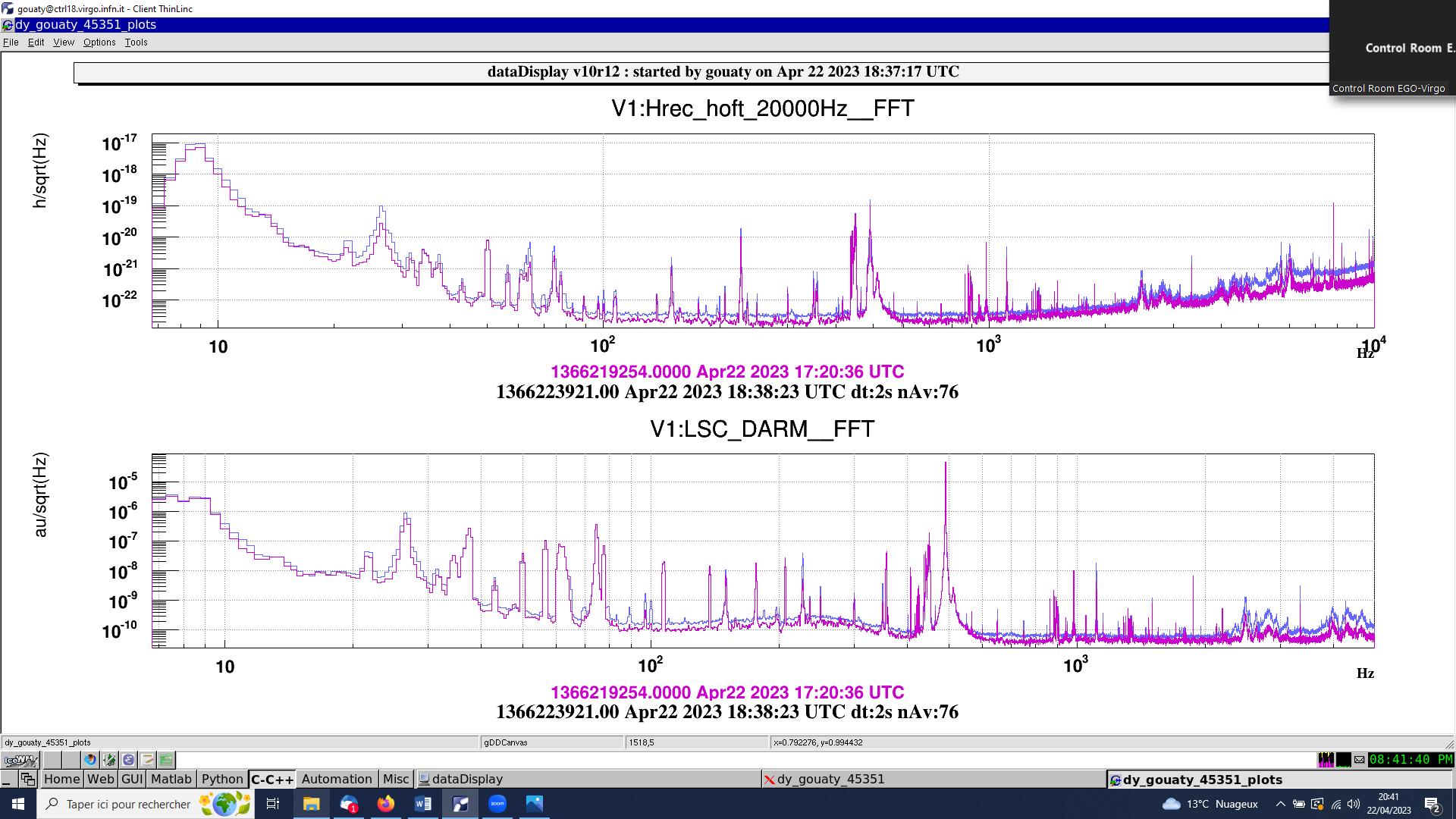
Collecting data with SDB1 bench misaligned in TY from 15h36 utc, for 23 min. Fig.3 compares the sensitivity curves with SDB1 misaligned in TY (blue) to the sensitivity curve when everything is aligned (purple). We can clearly see an increase of noise from ~70Hz.
Start injecting high frequency noise in SDB1_MAR_TY at 16h00m03 UTC
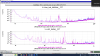
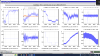
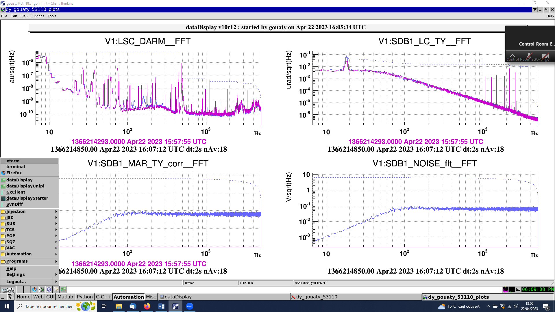
Noise amplitude 0.1 V/sqrt(Hz) (6.4 V RMS) at 16h04m52 UTC. Collecting data with the noise injected for 7 min. Stop noise injection at 16h12m18 UTC. Fig.4 compares the LSC_DARM spectrum with (blue) and without (purple) the noise injection.
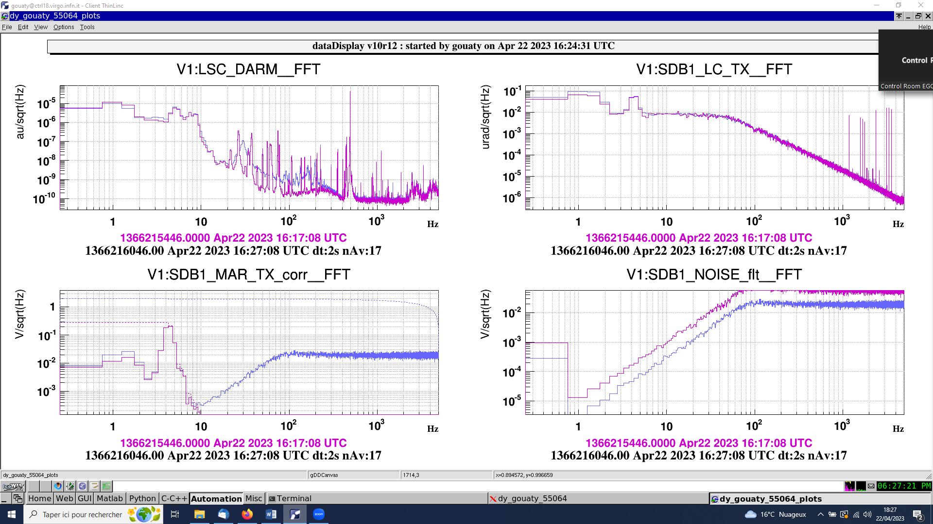
Start injecting high frequency noise in SDB1_MAR_TX at 16h17m40 UTC
Noise amplitude 0.02V/sqrt(Hz) (2V RMS), at 16h24m23 UTC. Collecting data with the noise injected for 5 min. Stop noise injection at 16h29m55 UTC . Fig.5 compares the LSC_DARM spectrum with (blue) and without (purple) the noise injection.
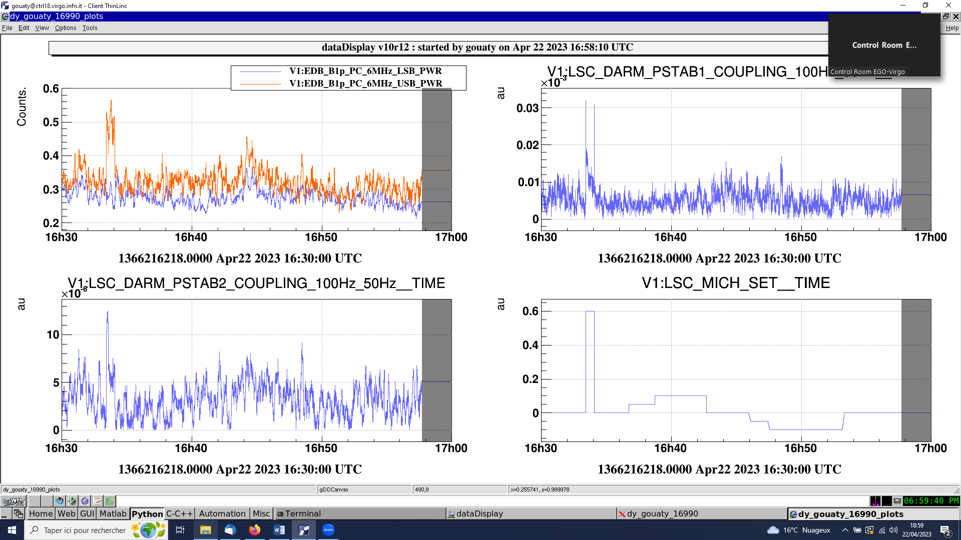
Adjusting MICH offset from 16h30 utc to 17h00 utc. I incidentally doubled the MICH offset from 0.6 to 1.2 at 16h33, then restored it to 0.6. We performed a small scan of MICH_SET but it is not clear that we can improve the tuning (Fig.6). Thus we leave it back to 0.6.
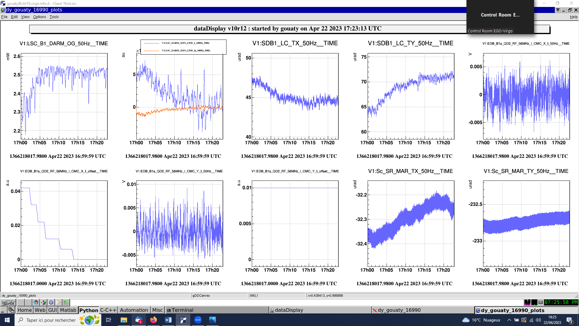
We realign the SDB1 bench in TY from 17h02 utc to 17h19 utc (Fig.7). Taking 8 min of reference data with bench aligned from 17h20 to 17h28 utc.
Injecting high frequency noise in SDB1_MAR_TX at 17h29m49 UTC: Noise amplitude 0.02V/sqrt(Hz) (2V RMS). Collecting data with SDB1 bench aligned and TX noise injected for 6min30 (Fig.8 : blue with the noise, purple without the noise). A careful analysis will have to be done offline to understand if the noise coupling is really reduced with respect to the misaligned situation. Stop injection at 17h36m39 UTC.
Injecting high frequency noise in SDB1_MAR_TY at 17h41m13 UTC: Noise amplitude 0.1 V/sqrt(Hz) (6.5 V RMS). Collecting data with SDB1 bench aligned and TY noise injected for 8 min (Fig.9: blue with the noise, purple without the noise). In this case the noise coupling seems to have increased (by a factor 2 or so) with respect to the misaligned situation shown on Fig.4. Stop injection at 17h49m22 UTC.
Reducing B5_QD2 vertical offset from 490 to 390 um at 17h55m37 UTC (90s of ramp time).
Scanning vertical offset of B1s QD2 RF (initial offset 0.010):
18h02 utc: offset at 0.015
18h06 utc: offset at 0.020
18h11 utc: offset at 0.025
18h14 utc: offset at 0.030
18h17 utc: offset at 0.035
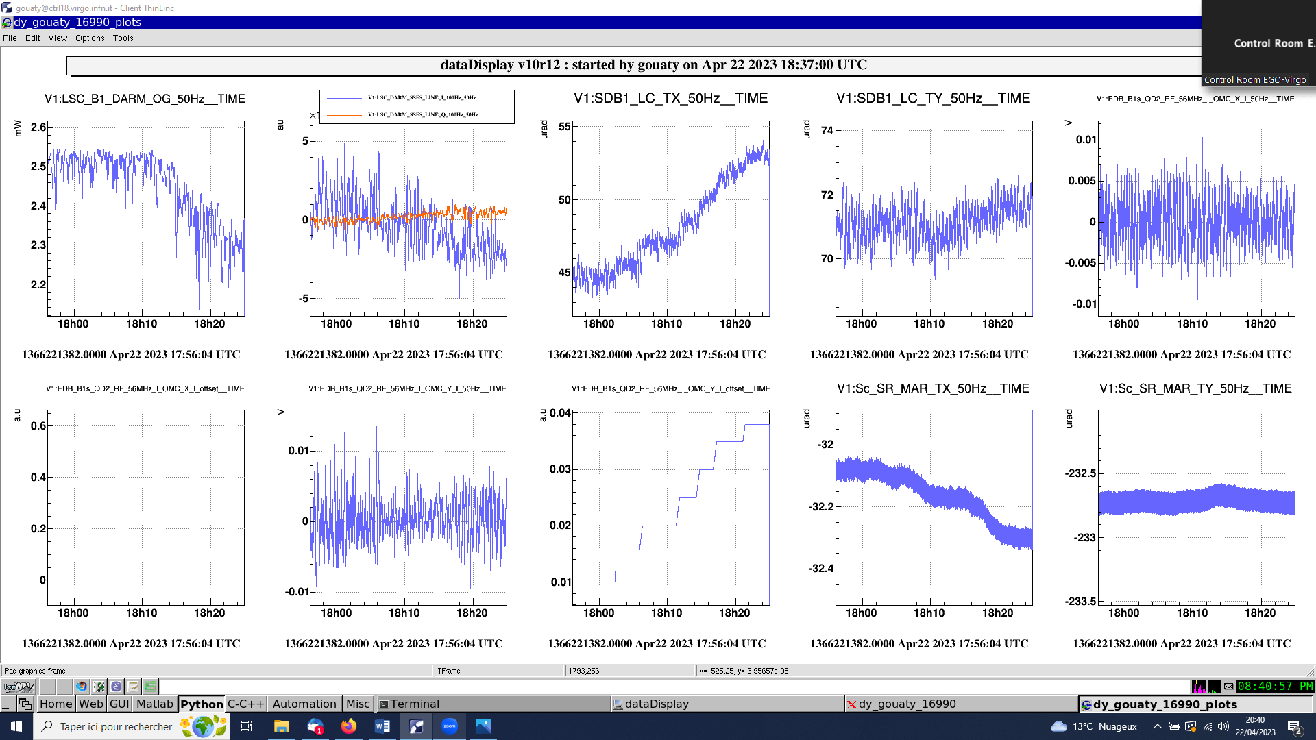
18h21 utc: offset at 0.038
The scan of the SDB1 bench in TX is shown on Fig.10. Looking at the evolution of the CMRF it seems that a vertical offset of 0.015 or 0.020 could actually be more optimal. During the scan, the bench has moved by a total amount of ~8 urad in TX. In this case there is no significant coupling to TY. Although the CMRF has worsened, the effect of the bench misalignment in TX on the CMRF seems to be smaller than when we misaligned the bench in TY.
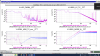
We collect data with the SDB1 bench misaligned in TX from 18h22 utc to 18h58 utc (36 min). Fig.11 compares the sensitivity with SDB1 misaligned in TX (blue) to the sensitivity when the bench was aligned (purple). There is a clear increase of the noise floor above 80 Hz, but this time there also seems to be an effect at lower frequency.
Injecting high frequency noise in SDB1_MAR_TY at 18h58m58 UTC : Noise amplitude 0.1 V/sqrt(Hz) (6.5 V RMS). Collecting data with SDB1 bench misaligned in TX and TY noise injected for 6min40 (Fig.12: blue with the noise, purple without the noise). It is not very clear how the noise coupling changed from the aligned position to the misaligned position in TX, to be analyzed more carefully. Noise injection stopped at 19h05m44 UTC.
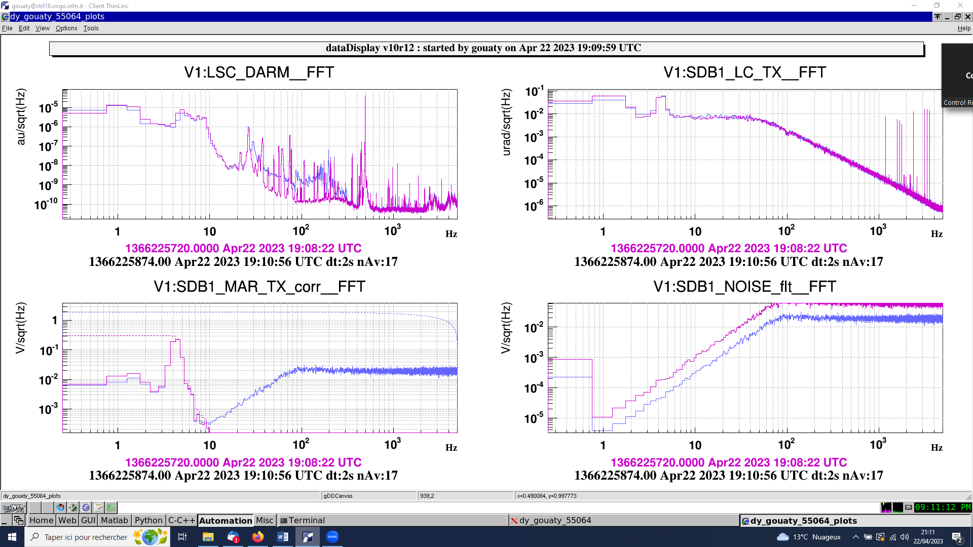
Injecting high frequency noise in SDB1_MAR_TX at 19h09m17 UTC: Noise amplitude 0.02V/sqrt(Hz) (2 V RMS). Collecting data with SDB1 bench misaligned in TX and TX noise injected for 6 min40. (Fig.13: blue with the noise, purple without the noise). This time the noise coupling is increased with respect to the aligned case (Fig.8). Noise injection stopped at 19h16m05 UTC.
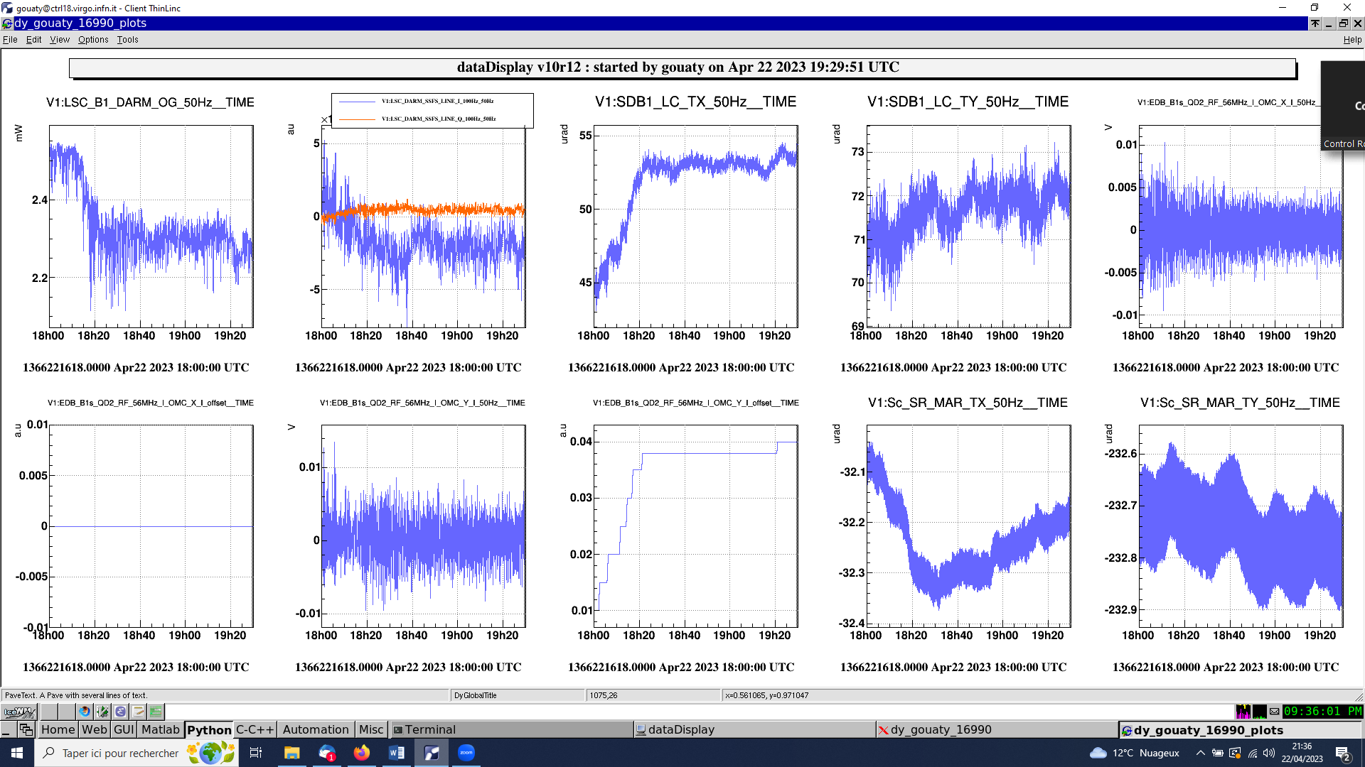
We try to misalign the bench in TX a bit more: B1s QD2 vertical offset at 0.040 at 19h20m40 utc. We can see more clearly the impact at low frequency, in particular on the noise bump around 26 Hz (Fig.14). However at high frequency the CMRF does not get as bad as when we misaligned the bench in TY. Although in term of optical gain both misalignments (TX and TY) are roughly equivalent (Fig.15).
Adjusting MICH_SET from 19h31m20 utc. Engaging MICH_SET loop at 19h44m15 utc. The loop is bringing the MICH_SET around 0.0. Fig.16 shows again the measurement sensitivity curve with the MICH_SET loop engaged (blue). The coupling of the power noise does not seem to play any role in the excess noise.
Realigning SDB1 in TX from 19h59 utc to 20h23 utc (see Fig.17). We will now use a vertical offset of 0.020 for the B1s QD2 RF signal, as this offset seems better from the point of view of the CMRF (while still maintaining a good optical gain).
Collecting data with SDB1 bench aligned (and MICH_SET loop engaged) from 20h23 to 20h36 utc.
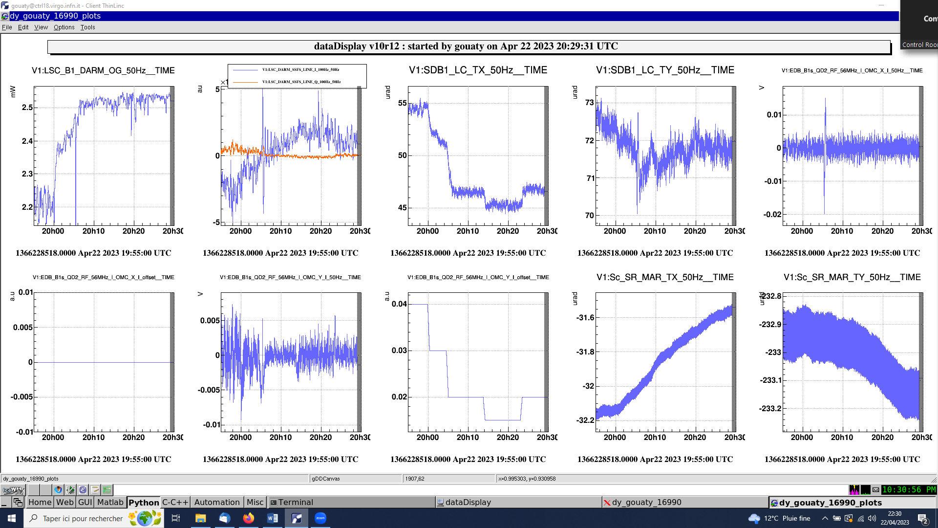
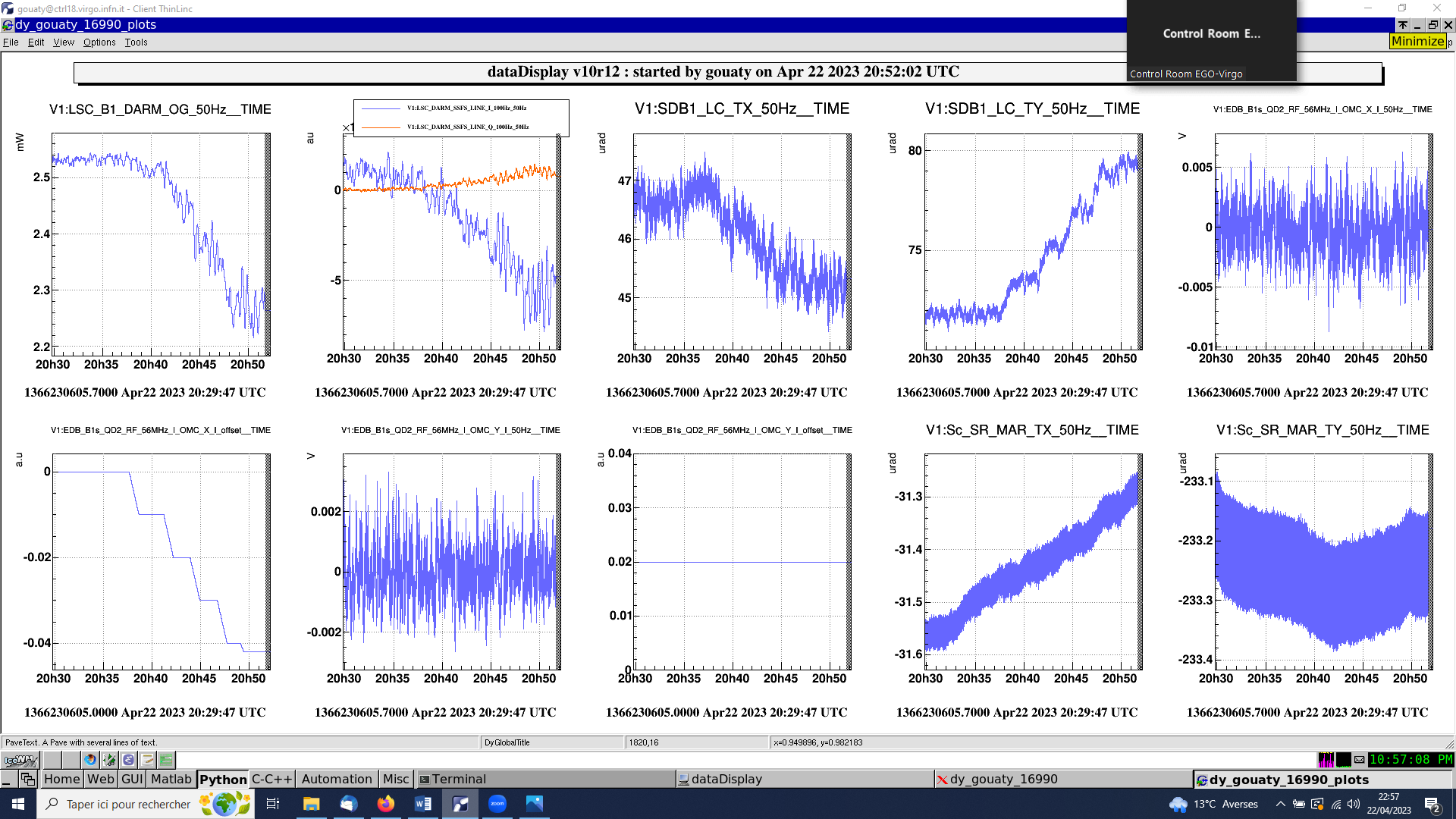
We try to misalign SDB1 in TY in the opposite direction (negative offsets in B1s QD2 RF horizontal signal), but this time we leave the MICH_SET loop engaged: scanning SDB1 TY from 20h37 utc to 20h51 utc (see Fig.18). Again we see a clear worsening of the CMRF. This seems to confirm that the TY misalignment has more impact on the CMRF than the TX misalignment.
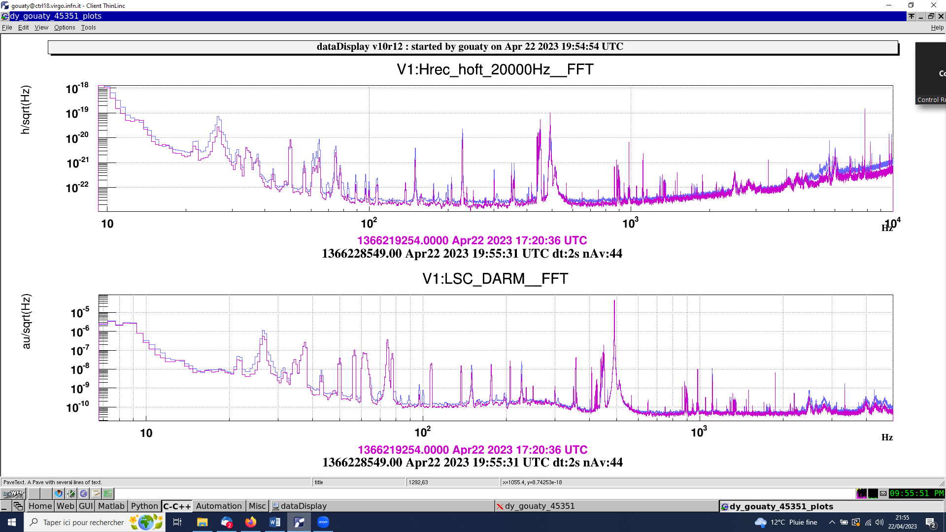
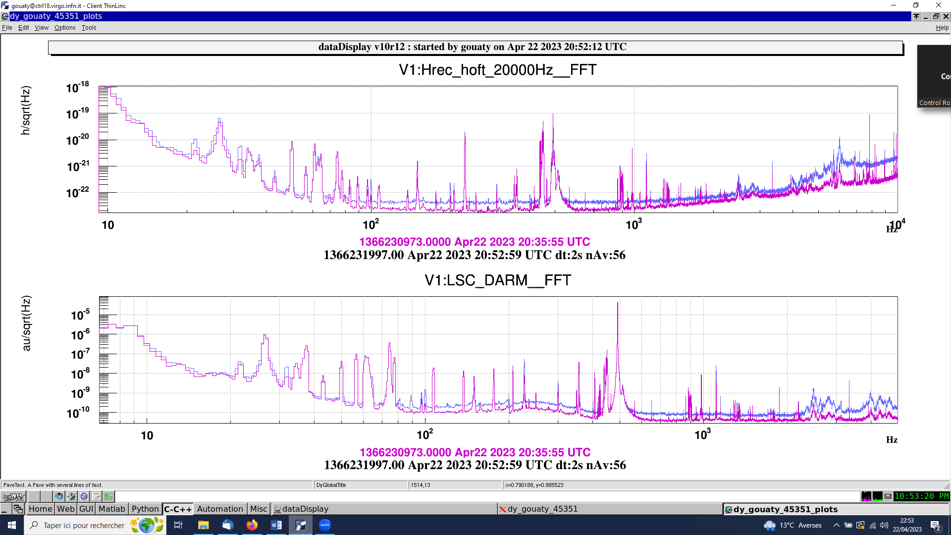
Collecting data with SDB1 bench misaligned in TY (opposite direction) from 20h52 utc to 21h00 utc. The impact on the sensitivity is shown on Fig.19 and seems comparable to what we observed with the TY misalignment in the opposite direction.
We realign SDB1 in TY from 21h00 to 21h20 utc. We leave a small negative offset in the B1s QD2 RF error signal (-0.005) as it seems to minimize the CMRF (Fig.20).
At the end of the shift we restored the standard configuration for the SR AA loop. The SR alignment loops are closed back using the B1_DCP signals at 21h29 utc (and the DARM_HF_LINE_AMPL is lowered back to 2e-6).
We leave the ITF in Low Noise 1 for the night.


