Reports 1-1 of 1 Clear search Modify search
AdV-COM (AdV commissioning (1st part) )
mwas - 20:55 Saturday 22 April 2023 (59915) Print this report
A good lead on origin of noise spoiling SSFS sensing

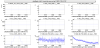
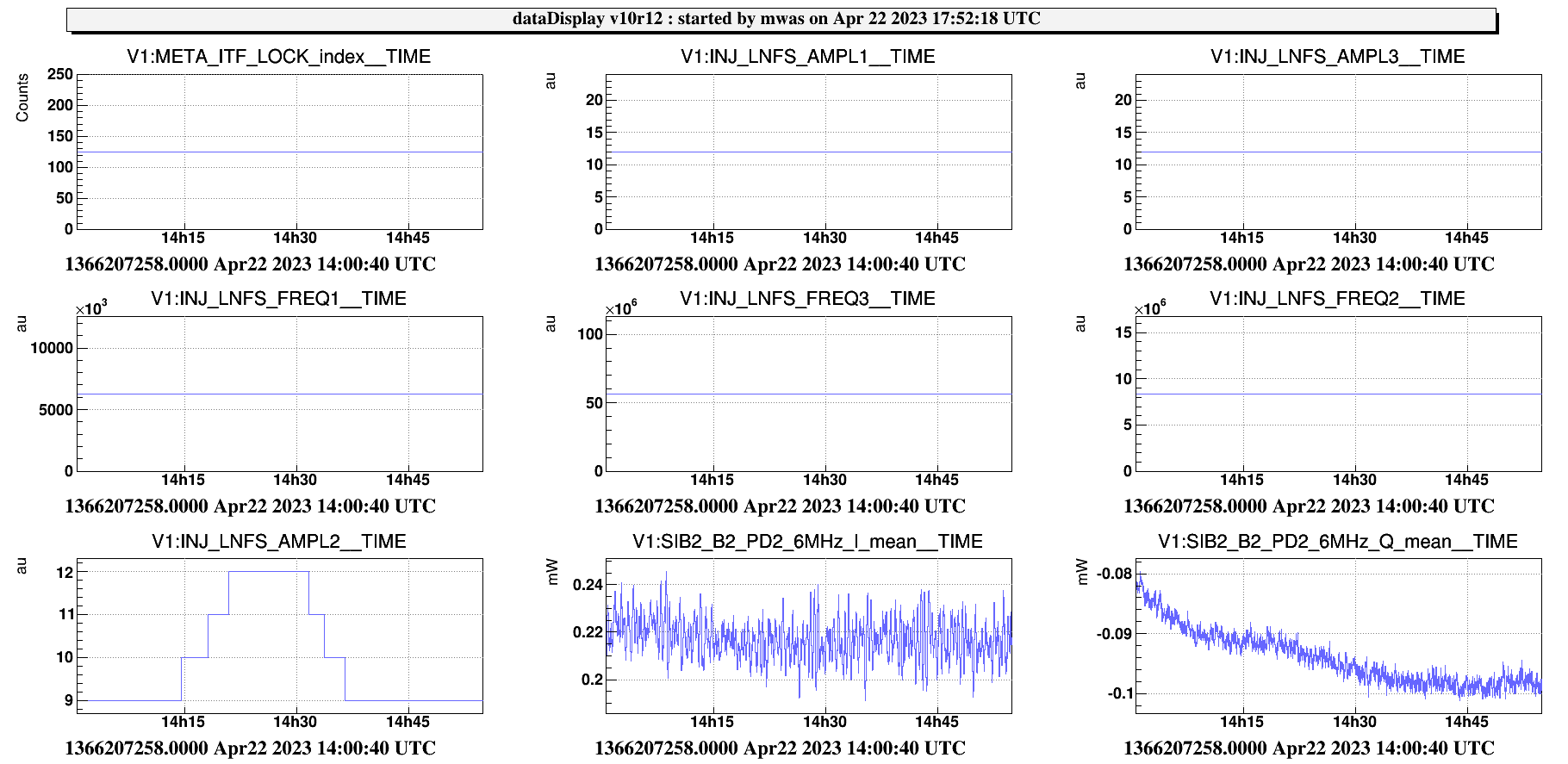
Figure 1. Romain has kindly increased the 8MHz modulation depth by 3dB during a few minutes in LN1 today.

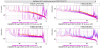
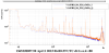
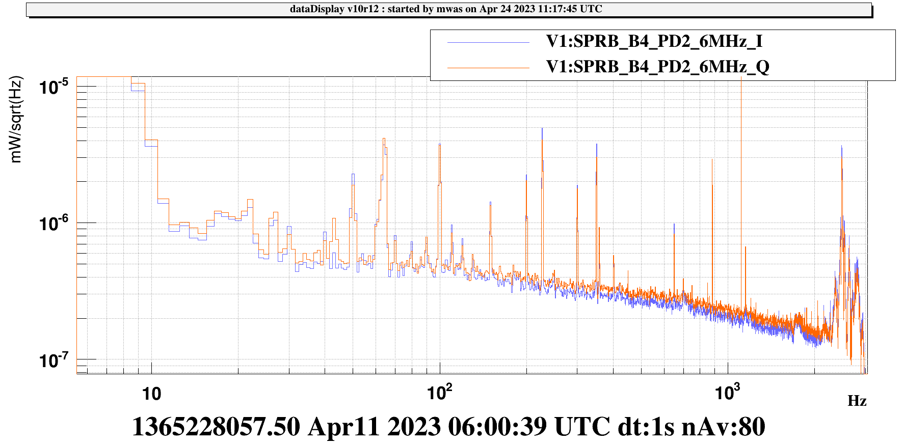
Figure 2 shows spectra in purple for the nominal modulation of 9dBm, and in blue/red the modulation with 12dBm of 8MHz. The spectrum of SSFS quadrature increases by about a factor sqrt(2), the B2 6MHz spectrum increases by ~sqrt(2) for both quadratures.  Also B4 PD1 56MHz Q (SRCL) increase by ~sqrt(2), this is explained as in the SRCL noise budget frequency noise dominates the error signal. So everything is consistent with the noise at 6MHz demodulations increasing by a factor sqrt(2) for both quadratures due to the increase in 8MHz modulation depth. The B2 8MHz quadrature spectrum doesn't change, which is consistent with the observation that 8MHz noise level depends on the 6MHz modulation depth.

So the issues seems to be that the modulation at 8MHz produce a noise at 6MHz proportional to the 8MHz modulation amplitude. That noise has the same amplitude in both quadrature of the 6MHz. It is very likely a white noise at the EOM level (i.e. constant level over at least a few kHz around the 6MHz frequency), that is the filtered by the IMC cavity pole at ~500Hz.

An open question is what is the origin of this issue.

  1. It may come from an interaction of the two sidebands, if both the 6MHz and 8MHz are modulated using the same crystal. Noise from the 8MHz modulation electronics, can travel through the crystal, and the become amplified by the resonant circuit of the 6MHz modulation. A way to test it would be to move the 8MHz modulation to another crystal, for example the crystal currently used for the 81MHz sideband.
  2. It may come from the modulation electronics itself, if the resonant circuit is not selective enough, and we see the tails of the resonance at 8MHz modulating the light at 6MHz.
Images attached to this report
Comments to this report:
mwas - 14:59 Wednesday 26 April 2023 (59952) Print this report

Figure 1 shows the noise induced at 6MHz by the 8MHz modulation on the B4 photodiode. The demodulation phase is not well tuned, so these spectra show each a part of the noise seen SSFS quadrature signal (in the in-phase signal any noise is eaten away by the SSFS high loop gain).

At 80Hz the noise level is ~5e-7mW/rtHz for both quadratratures, which correspond to ~7e-7mW/rtHz in the SSFS error signal quadratures. The question is how to relate that to noise at the level of the EOM modulation, and there are several answers depending on the assumption taken.

If one just look at one sideband the the signal at 6MHz is

B4_{6M} = 2 \mathrm{Real}\left[ E_0^*(E_6 + E_n) \right]

With E_0 the carrier field, E_6 the sideband field, and E_n the noise that we are trying to quantify. On the B4 PD we have 40mW of carrier light, the 6MHz sideband at the modulation has 1% of the carrier light power, and the optical gain of the 6MHz and carrier are similar, so one can assume that also on B4 the 6MHz is 1% of the carrier, so 0.4mW.

B4_{6M} = 2\sqrt{40 \text{mW} \times \text{0.4}} \left( 1 + E_n/E_6 \right ) = 7\times 10^{-7} \textrm{mW/rtHz}

Which would mean that the relative fluctuation of field at 6MHz at the input is E_n/E_6 ~ 1e-7 1/rtHz

But in reality we have two sidebands, and the mean field on B4_6M should in theory be zero, not 8mW like in the computation above. In reality, it is not zero due to the SRCL and MICH offsets, and there is a field of ~0.3mW on the 6MHz signal. So a factor ~25 reduction compared to the single sideband computation. If we assume that the noise between the upper and lower sideband also cancels by the same factor, then at the modulator level it could be E_n/E_6 ~ 2.5e-6 1/rtHz.

I don't really trust the evaluations above, but it is a starting point to compare with expectations at the modulator level. In other units the noise we try to understand at the modulator level is somewhere in between -140 dBc and -110 dBc, depending on which assumptions one take.


Images attached to this comment
nocera - 11:22 Thursday 11 May 2023 (60176) Print this report

In a quick and dirty attempt to understand something more about the origin of the 6 MHz signal on the 8MHz modulation line, on Tuesday morning, May 9th, a ~25 dB deep notch at 6 MHz has been added at the output of the RF Amplifier driving the 8MHz EOM resonant circuit.
It has been conceived as a test to understand whether the coupling comes (or not) upstream the modulator itself.

mantovani - 11:28 Thursday 11 May 2023 (60177) Print this report

This morning I've done the test to raise back the 8MHz to 9dBm

the noise is visible in figure 1.

Images attached to this comment
Search Help
×

Warning

×