Reports 1-1 of 1 Clear search Modify search
AdV-ISC (Commissioning up to first full interferometer lock)
derossi, mantovani, gouaty, hui, bersanetti, ruggi - 17:23 Friday 07 April 2023 (59687) Print this report
ISC shift - modulation depth at 15dBm, set point of MICH vs RIN in LN1

The first unlock of this morning was manual (by error).

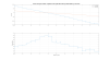
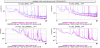
At 07h57 UTC unlock due to DIFFp high gain oscillation (plot 1). This was due to the servo of the DIFFp, which was working up to LN1 (since after that no coherence was visible due to the lowering of the line, which stops the servo). Unfortunately in the OMC lock phase the alignment loop is not optimal, we observe a transient in which the SR is aligned, then when the SR is aligned back in LN1 the sideband increase and the absence of DIFFp servo made the gain of the loop too high causing the unlock.

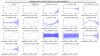
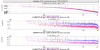
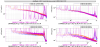
The solution implemented is to open the SR alignment loop after CARM 1f and close it back at LN1 with a slow ramp. see Figure 1 and 2.

ALS NARM: since the ramp was not scanning enough to find the TEM00, we changed the vco ramp set from 0.2 to -0.1 and vco ramp amp from 0.4 to 0.8

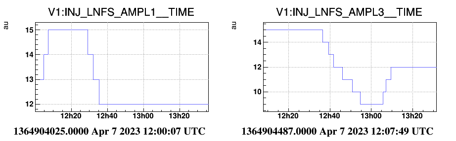
In LN1 we had to increase the DIFFp lines ampl for tx and ty from 1e-4 and 1e-3 to 2e-4 and 2e-3 because there was poor coherence with the line to let the servo to work during the change of modulation index for 56MHz (we have put back them to the standard config).

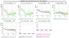
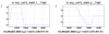
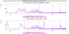
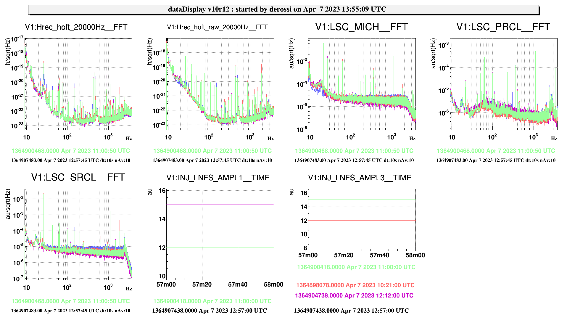
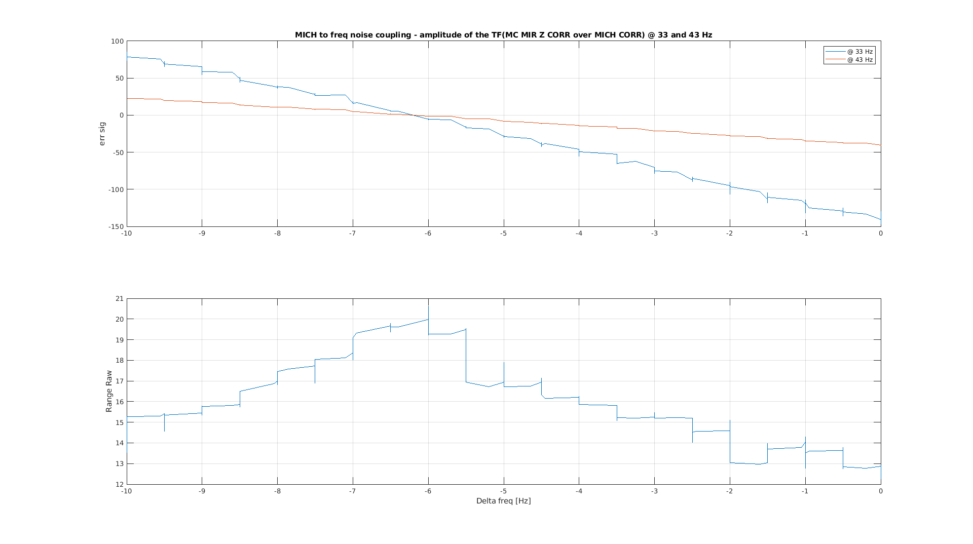
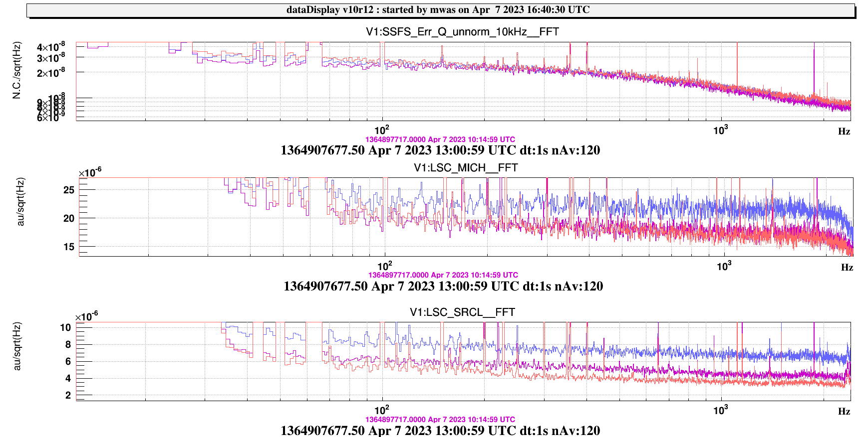
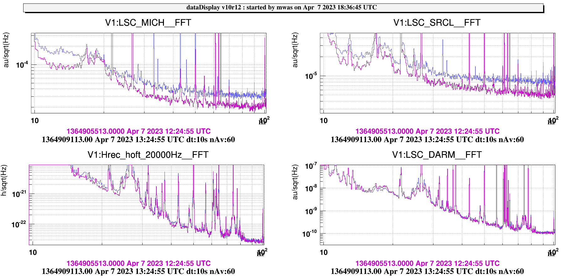
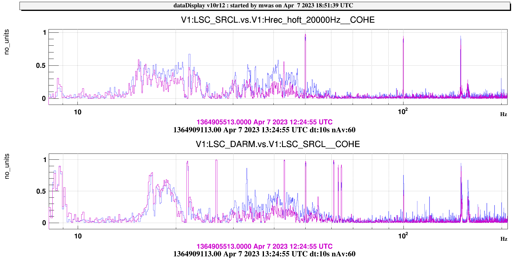
The purpose of the shift was to increase the modulation amplitude of the 56MHz and 6 MHz to 15 dBm and check if we could gain at low frequency.  We removed the clipping on the SRCL set to be able to compare the different situations (now it is at 40). It was impossible to improve the sensing noise nor the sensitivity. We also tried to decrease the 56MHz to have the quadrature smaller, but still no change at all was visible (plot 3). The trend is visible in figure 4.

We also have tuned the Fmoderr with the calibration done yesterday but we were already at the zero. The calibration is visible in Figure 5.

We also tried the test of balancing the sidebands putting a MICH offset. See figure 6 After a while EPRB PC singal disappeared.

Moreover we tested the more perfomance filter for DIFFp ty which works correctly but I reverted the engagment since it is not yet manageble by the automation and we can not acquire DIFFpty with that loop. The effect on rms is visible in Figure 4.

Images attached to this report
Comments to this report:
bersanetti - 20:08 Friday 07 April 2023 (59700) Print this report

The new filter for DIFFp TY was re-engaged and kept until the unlock at 17:46:55 UTC.

Unfortunately, as spotted before, I confirm that despite being visible, the GNAME SW_DPTY (and SW_DPTX as well) cannot be read (nan is returned) or written by PythonVirgoTools. So, it can't be automated yet.

I disengaged the filter directly from the ScWEPSDi DSP card.

mwas - 20:55 Friday 07 April 2023 (59697) Print this report

The effect of the 56MHz modulation depth changes is clearly visible in the MICH/SRCL error signal noise levels, but one needs to to choose appropriate FFT lengths or data duration, to be able to see small changes in wideband noise. The figures in the logbook have factor 3 statistical fluctuations, so one cannot conclude much from them.

Figure 1 shows spectra with 1s long FFT, and one minute of data in each case. In purple is the 12dBm case, in red the 15dBm case and in blue the 9dBm case. For SRCL, the three curves are separated by a factor ~1.4 each, which is what one would expect from steps of 3dB in modulation. For MICH the 9dBm case is clearly worse, (by about 1.3), and the 12dBm and 15dBm are the same, so it seems that the MICH noise sensing becomes limited by something else when going above 12dBm.

Figure 2, looking at later data when the modulation depth was reduced

Figure 3, comparing the 15dBm on 6MHz and 56MHz case (purple) and 12dBm on 6MHz and 56MHz (blue), with 5min for each time. MICH and SRCL are both with the expected factor ~1.4 lower sensing noise. And h(t) also improve slightly just below 20Hz, and between 40Hz and 45Hz, which are the two frequency bands where there was coherence between DARM and SRCL

Figure 4 shows the coherence between the SRCL and DARM / h(t) for the same times, and indeed the coherence with SRCL is smaller when the modulation depth is larger

Images attached to this comment
mwas - 8:52 Saturday 22 April 2023 (59911) Print this report

Figure 1. Shows the test of changing the modulation depth of sidebands. In purple with 12dBm on the 6MHz, and in blue/red with 15dBm. What is surprising is that the spectrum of B2 8MHz increase with a higher modulation depth. With a noise in a shape of a pole at ~500Hz increasing.

A possible explanation is that the modulation of the 6MHz adds phase noise at the 8MHz frequency. Are the two sidebands modulated using the same crystal?

This could be also an explanation for the SSFS error signal and quadrature being affected by a noise shape like ~500Hz pole. If the reverse process happens, the 8MHz modulation creates a phase noise at 6MHz. A simple check of that hypothesis is to increase or decrease the 8MHz modulation depth by ~3dB and see if that changes the spectrum of the SSFS quadrature signal. There might be already past tests with such a change that just need analyzing.

Note that we don't have a good way of measuring the 6MHz phase directly, as all the photodiodes on B2 and B4 have a notch at 12MHz.

Images attached to this comment
Search Help
×

Warning

×