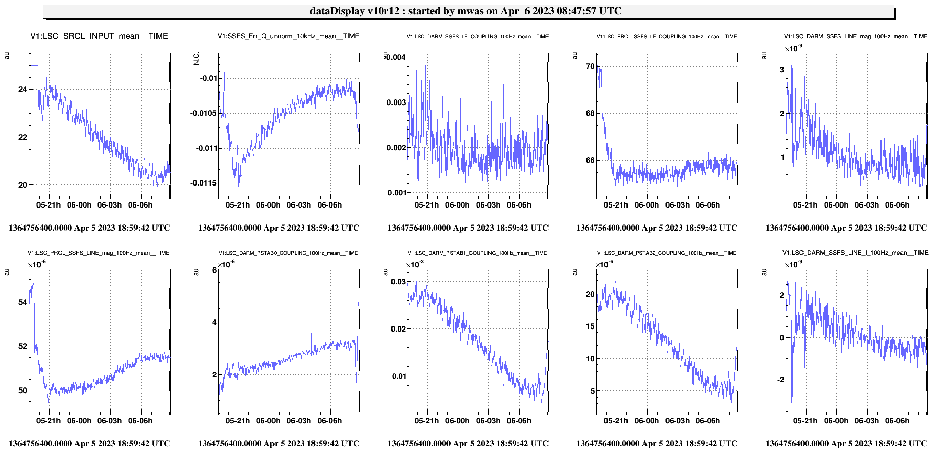
I have tried to make a noise budget of the data of this morning that is at ~20Mpc of BNS range.
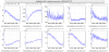
Figure 1 shows the trend over the night, which highlights one issue with trying to use fix transfer function from PSTAB and SSFS measurement of coupling to DARM done last week. The coupling of the SSFS at 3345Hz decreased by a factor 4, but the coupling of the SSFS at 227Hz decreased by at most a factor 2, so the shape of the coupling transfer function has changed. Also the PSTAB coupling changed during the night, it improved by a factor 4 at 1.5kHz and ~200Hz, but it got worse by a factor ~1.5 at ~40Hz where the PSTAB0 line is.
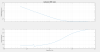
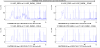
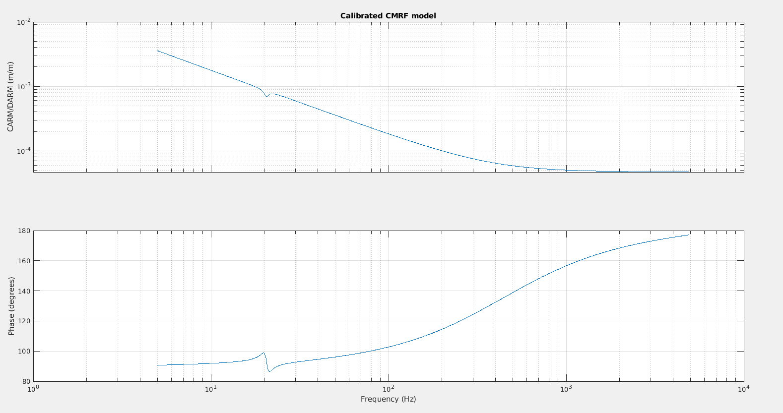
Figure 2 I have tried to adjust for the change in SSFS coupling shape, unlike before when a coupling lower at 200Hz was needed, now a flat coupling of phase noise to B1 between ~200Hz and ~1kHz explains well both lines of the SSFS. This result in a coupling between CARM and DARM as shown in the figure because of various cavity poles.
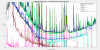
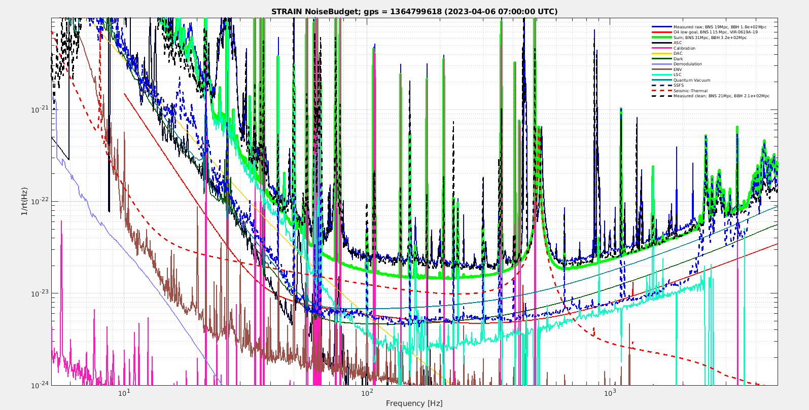
Figure 3 shows the resulting noise budget. With a large gap (40%) in the understanding of noise in the 100-300Hz band. The missing noise seems to be slow raising at low frequency.
At 1kHz the measured noise is well explained by understood noises (quantum noise, B1 PD electronic noise, SSFS sensing noise, and laser RIN).
At low frequencies, below 80Hz, the noise seems well explained by LSC contributions
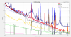
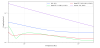
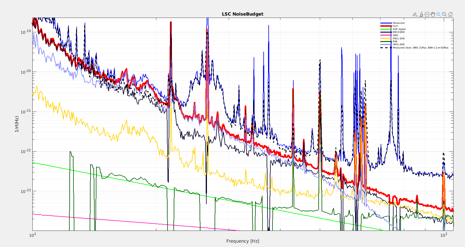
Figure 4 shows the contribution of the noises put into LSC at low frequency. With the better phase noise subtraction in MICH, and strong MICH roll-off, MICH and SRCL noise are comparable at most frequencies. The 26.6Hz SRCL line has lots of sidebands, we should consider trying to understand why the coupling is fluctuating so much in time, and if possible lower the SRCL line. For MICH, there has been so many changes that the projection may not be accurate anymore.
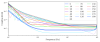
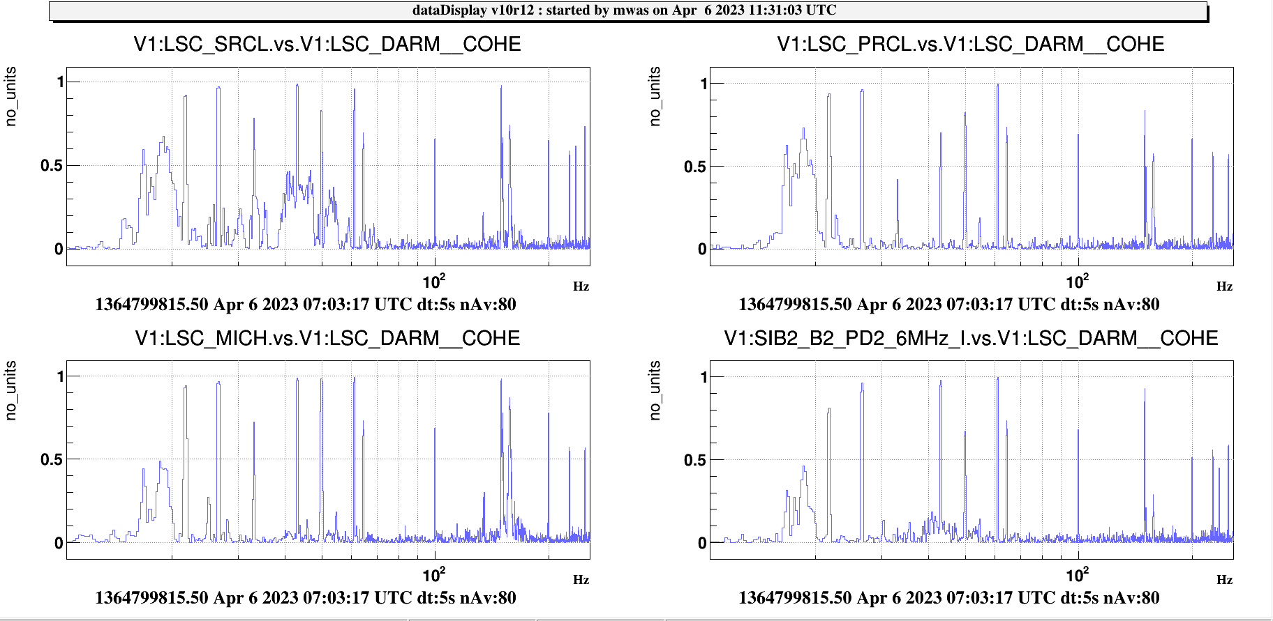
Figure 5 shows the coherence with the various LSC signals, SRCL is the one which has the most coherence around 20Hz and between 40Hz and 50Hz.
The projection of SR onto the sensitivity is done with a model from Optickle, which results in a 1/f^2/(1 + 1j*f/450) coupling of SRCL displacement to DARM displacement. So one could try to do a SRCL_CORR feed-forward to DARM_CORR using a high-passed version of 1/f^2/(1 + 1j*f/450) and adjust a gain and sign, if fully fitting the transfer function from the data is too difficult. To improve on the model, one would need to also compensate for the difference in SR and NE/WE coil response that have a pole at different frequency.
Coming back to the CMRF, figure 2 can be compared to what has been simulated a few years ago in Finesse, VIR-0062A-21, for different temperatures of the input mirrors (etalon effect). Two of the figures from that document follow.
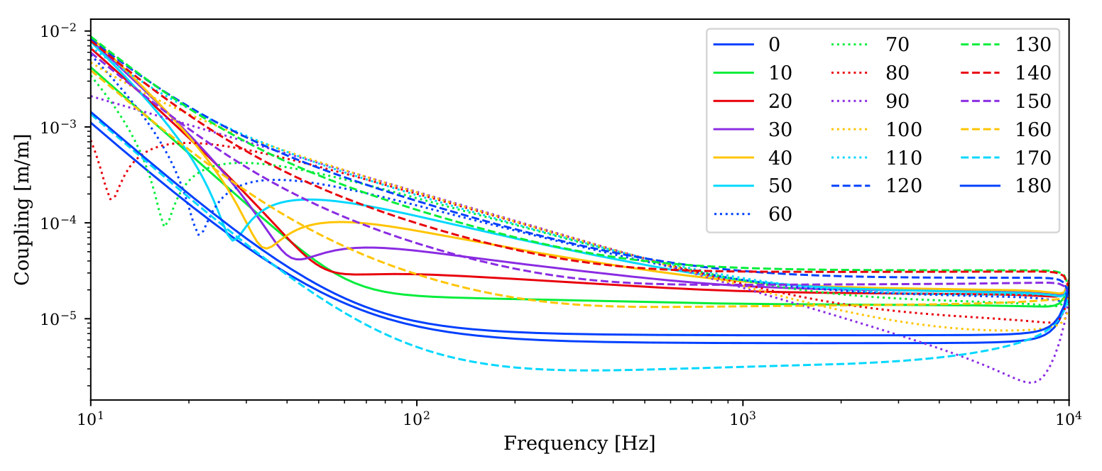
Figure 6 shows the simulations of a perfect interferometer, with different etalon tunings. It should be the same units as what is used in figure 2, DARM/CARM.
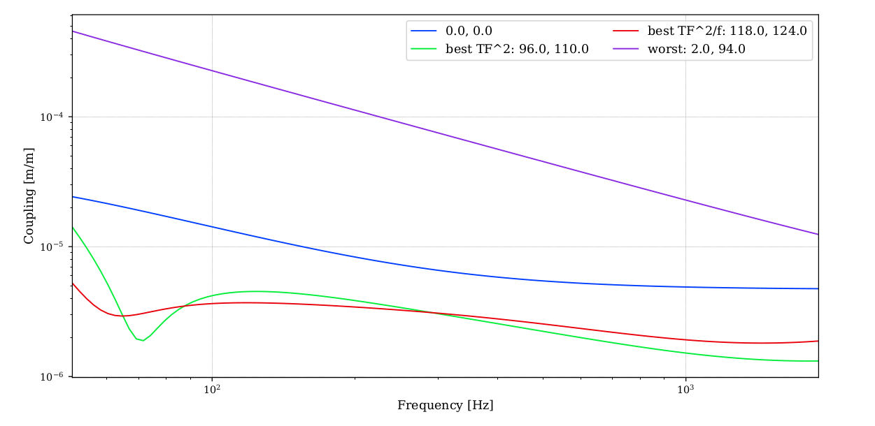
Figure 7 is in many ways more useful, it is the simulation of an imperfect interferometer, with ~1.5% mismatch between the two arms, and similar level mismatch of the input beam to the arms. The coupling we had this morning is compatible with these curves, so with a random and rather bad tuning of the etalon effect. Note that with an imperfect mode matching Etalon affects both the low frequency coupling, and the high frequency coupling of the frequency noise.