Reports 1-1 of 1 Clear search Modify search
AdV-DET (Output mode cleaner)
mwas - 16:36 Friday 23 September 2022 (57166) Print this report
Dangerous flash through resonant OMC

Summary:

  • We had a powerful flash with the OMC locked in CARM null and the fast shutter closed only after the flash finished
  • That flash could have damaged the OMC (based on the O3 experience)
  • The good news is that the OMC seems to unlock by itself due to thermal absorption in the fused silica
  • We shouldn't open the OMC shutter in CARM null until a solution is found

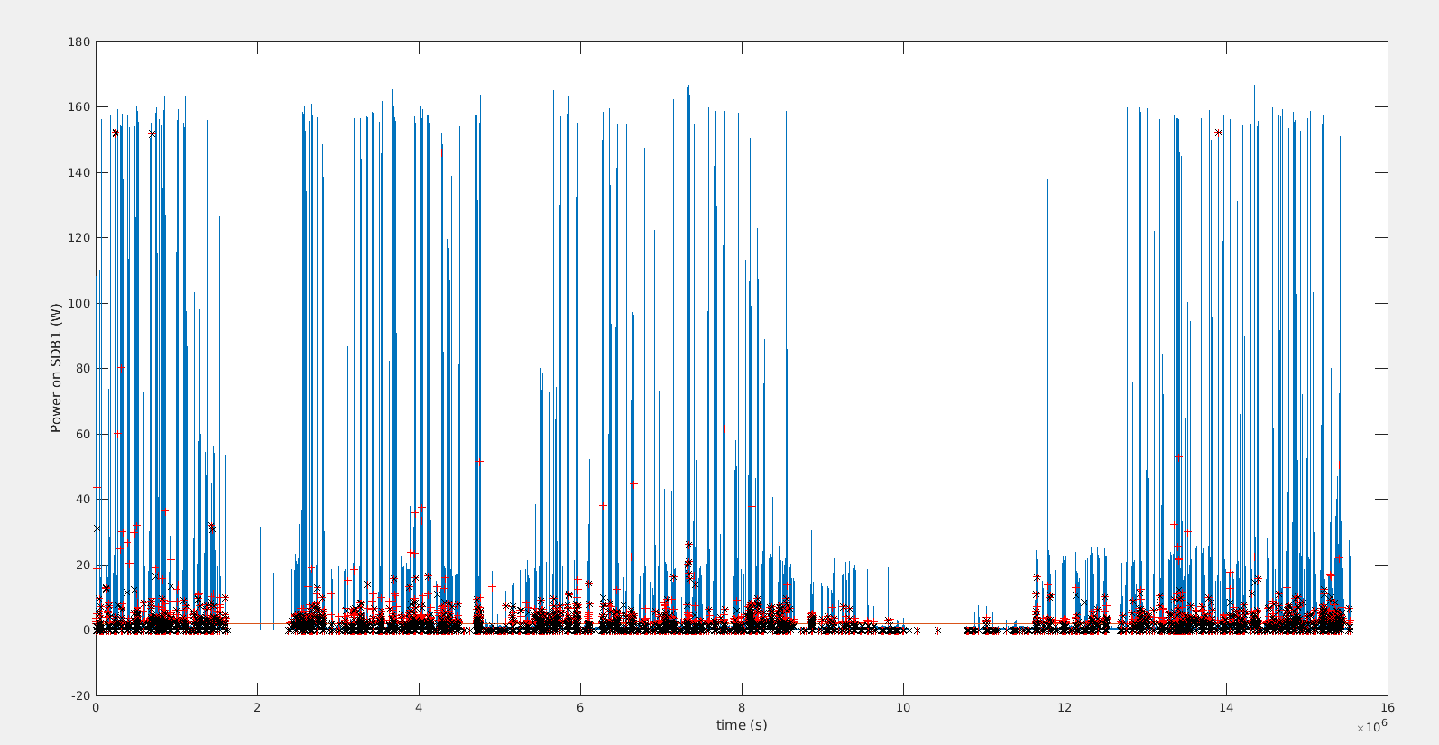
While investigating past unlock flashes to find what a safe threshold for the dark fringe power could be for the OMC I have found that the worst case scenario has already happened on Aug 30.

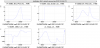
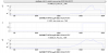
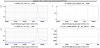
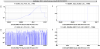
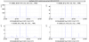
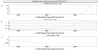
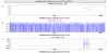
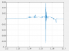
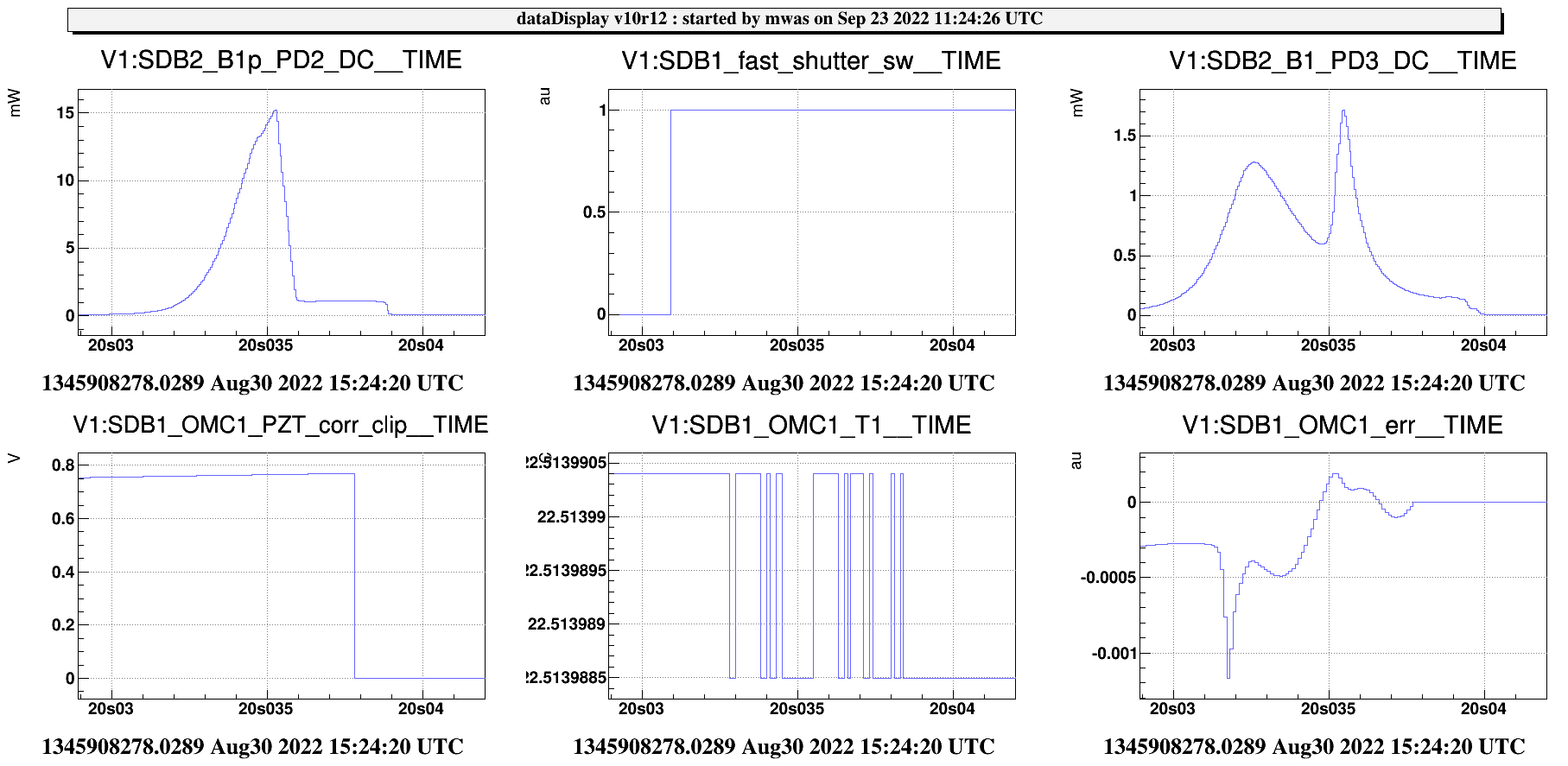
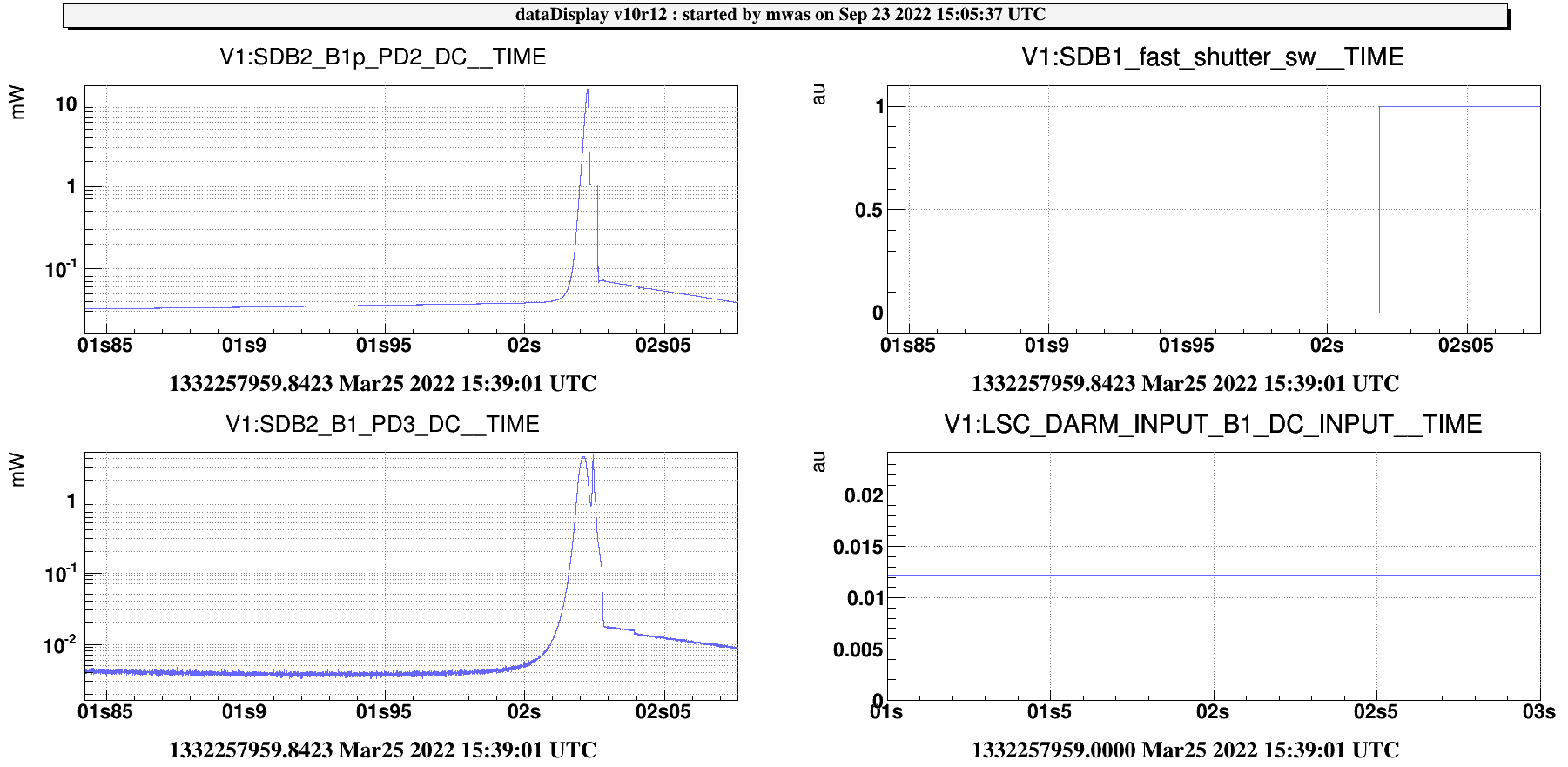
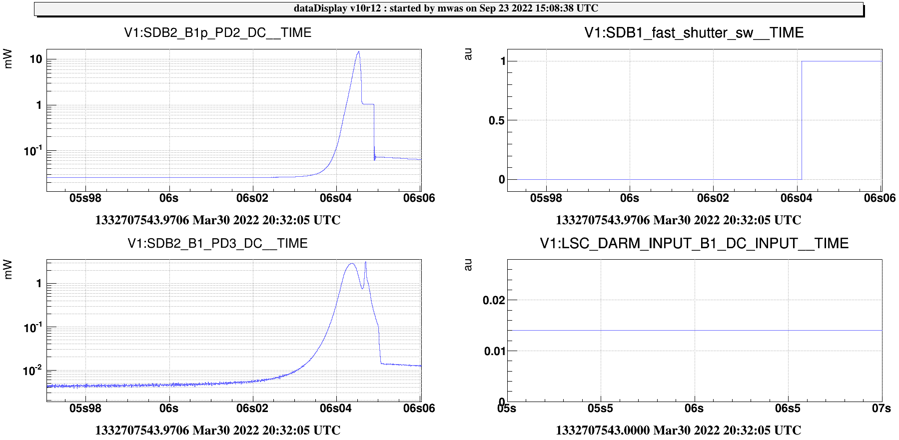
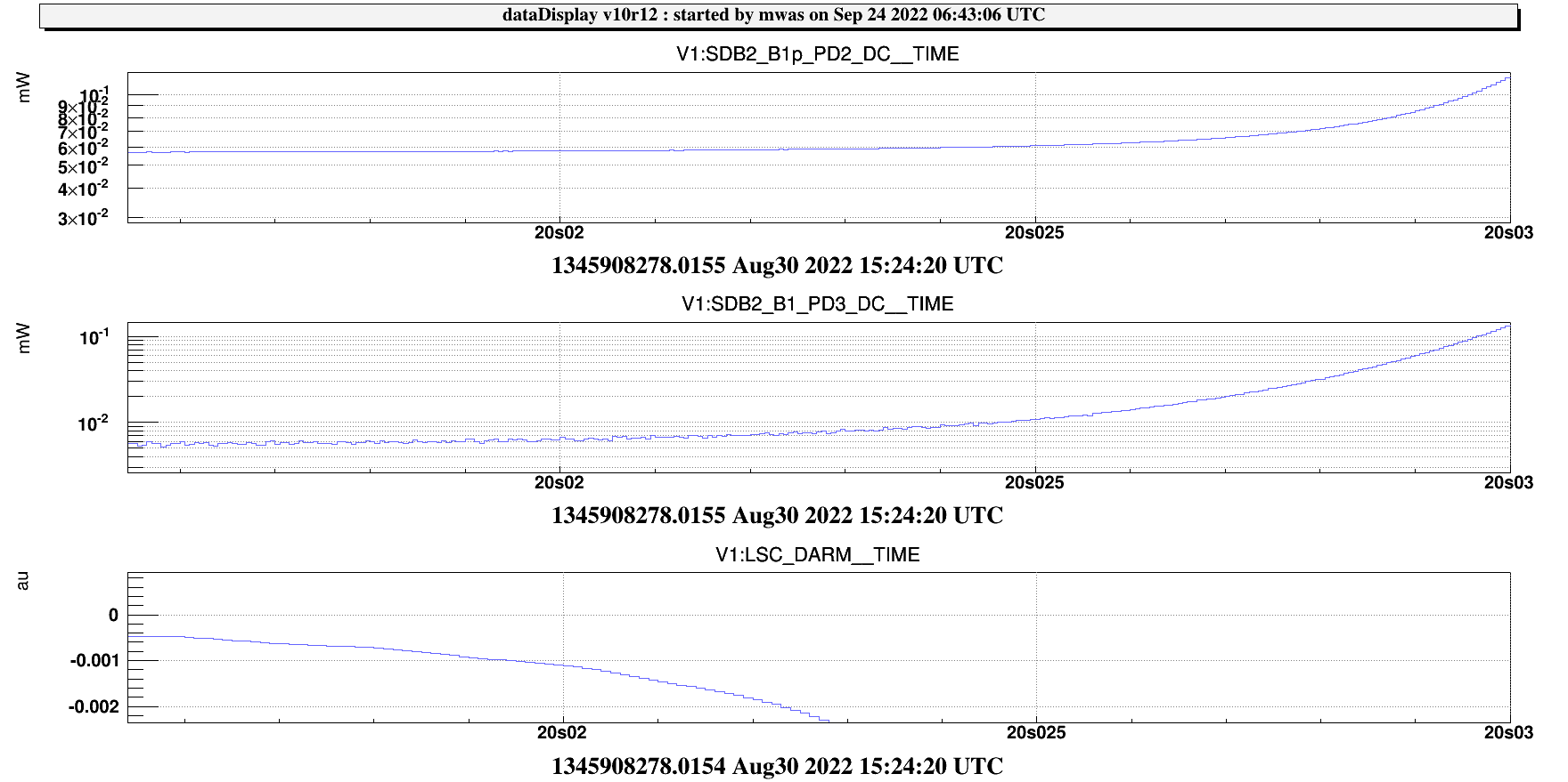
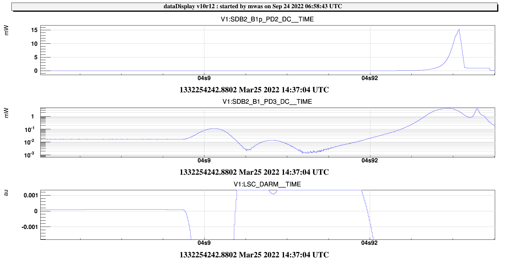
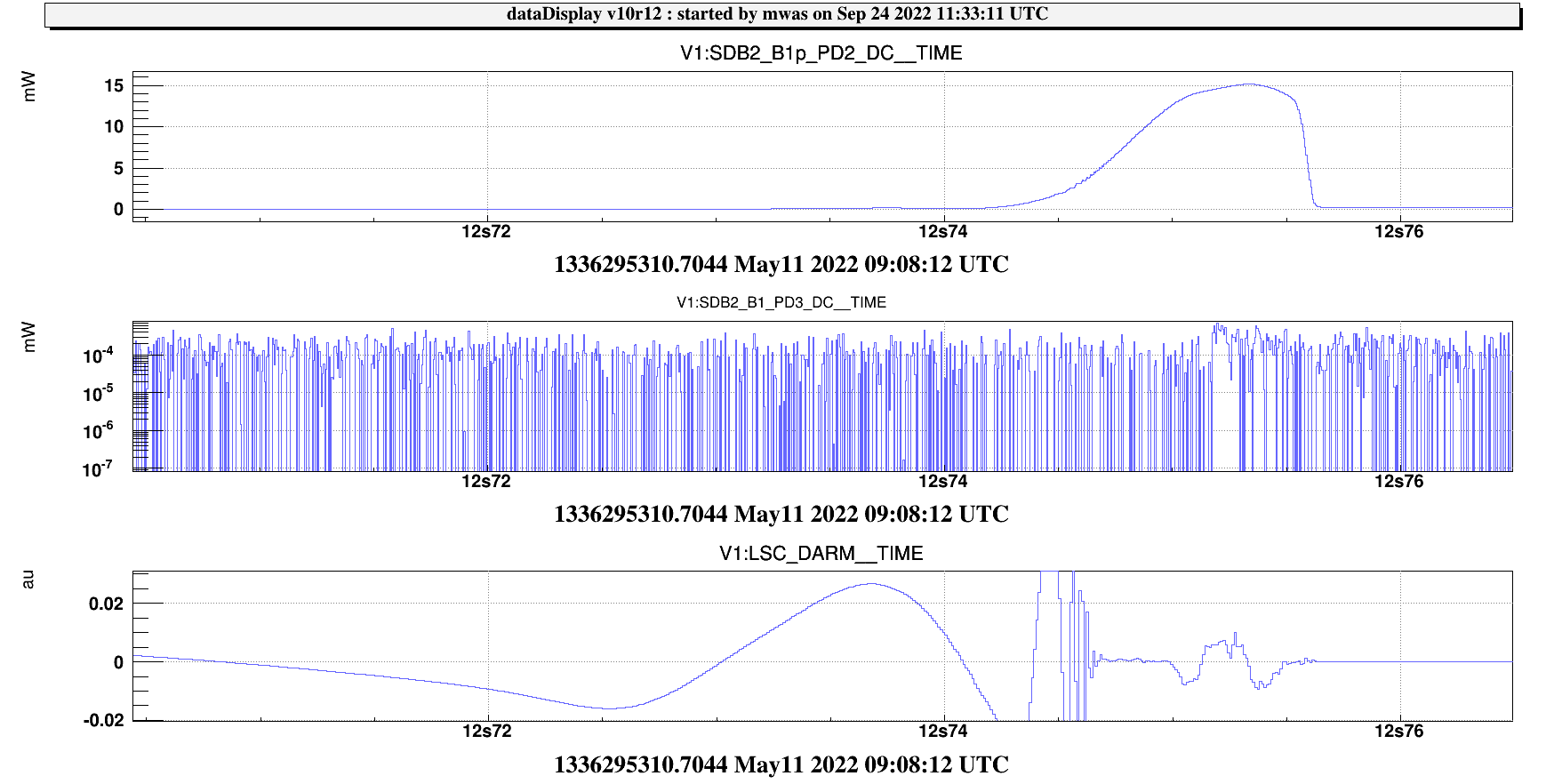
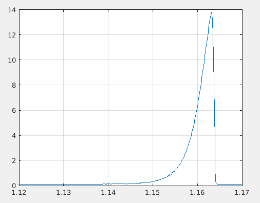
Figure 1 is a zoom on the unlock flash, the OMC was then on resonance, locked using B1 PD3. This was a failed attempt to hand off DARM to DC read-out

On B1p PD2 one can see the power quickly increasing in 2ms, the 15mW peak corresponds to 150W on SDB1. This triggers the closure of the shutter of the PD itself at 35.5ms and the switch off its voltage bias. So the top of the peak is not visible on B1p PD2. The fast shutter is triggers at 31ms, but it takes 9ms to close, so it cuts the beam at 40ms, which is beyond the edge of this figure.

On B1 PD3 one can see the OMC power transmission, it is a 0.1% pick-off from the transmission, so the 1.7mW peak, corresponds to 1.7W in transmission of the cavity and 566W resonating inside the cavity. For comparison, a flash of 500W peak power on an unlocked OMC has burned a hole in the coating of an OMC in 2018. That was well below the damage threshold of the coating, and the theory is that some dust on the coating had burned the hole back in 2018.

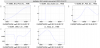
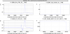
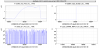
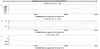
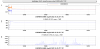
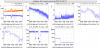
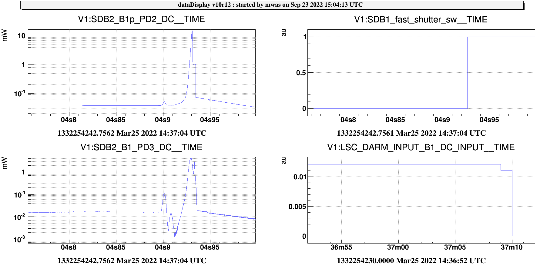
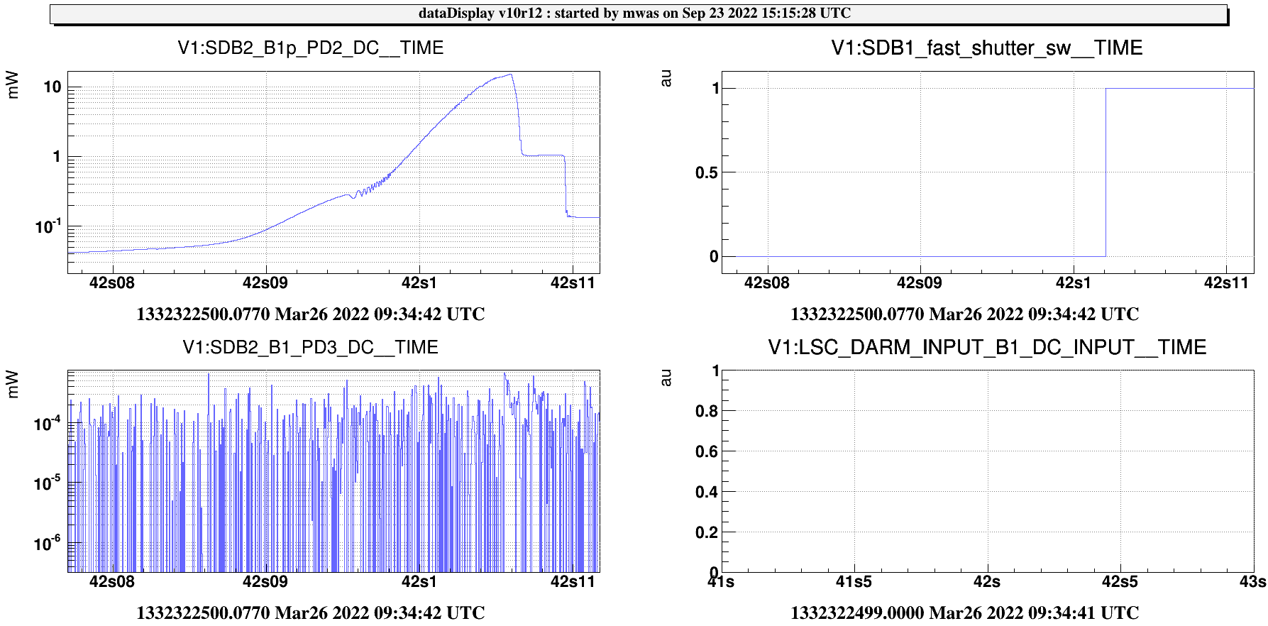
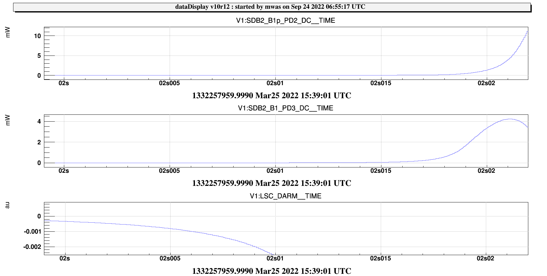
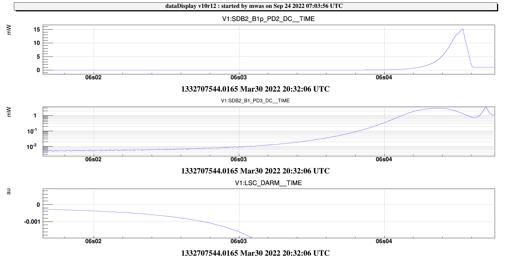
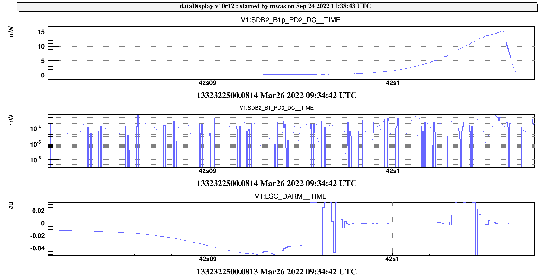
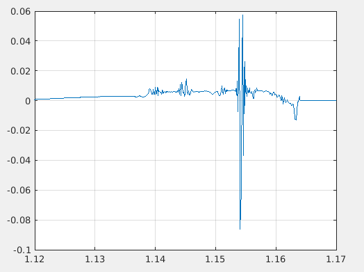
Figure 2 is a zoom that higliths that the power evolution in transmission of the OMC does not match the impinging beam.

B1 PD3 has a maximum at 32.5ms, while B1p PD2 is increasing continously to 34.5ms. The ratio of the two power (zz_mwas_ch) has a maximum earlier on at 31.5ms, at the same time the OMC error signal starts decreasing, has a large deviation at 31.7ms. Note that the OMC error signal is low passed at 200Hz, so these evolutions are actually much faster than the bandwidth of the error signal. I expect that what is happening is that the absorption in the OMC unlocks the cavity. The power ratio shows us that at 31.5ms the OMC transmission efficiency start falling off as the OMC is driven off resonce by the temperature dependence of the optical index, and we partially see it with some delay on the error signal. The thermal diffusion time scale for a size comparable to the beam waist is 1s, so any thermal deposition that happens faster than that stays were it is. I.e. the heat / temperature increase is not removed from the beam path by thermal conductance.

Also one can see that the B1p PD2 is increasing by a factor 10 in 2ms, this correspond to an e-folding time of 0.9ms, much shorter than the 2.8ms cavity storage time. This is somewhat unexpected, but it does make sense. SR is lowering the finesse of arm cavities towards the anti-symmetric port, if the double pole cavity is at 450Hz, in principle the storage time could be as short as 0.35ms.

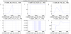
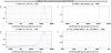
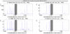
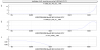
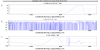
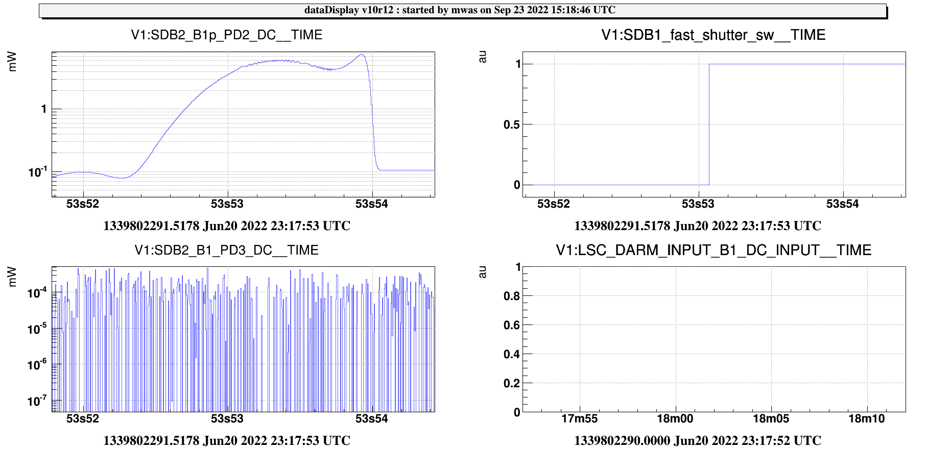
Figure 3 The OMC control itself turnes off the PZT only at 38ms, and the control loop bandwidth is ~3Hz, so the PZT is not doing anything during this transient.

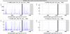
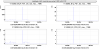
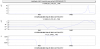
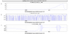
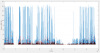
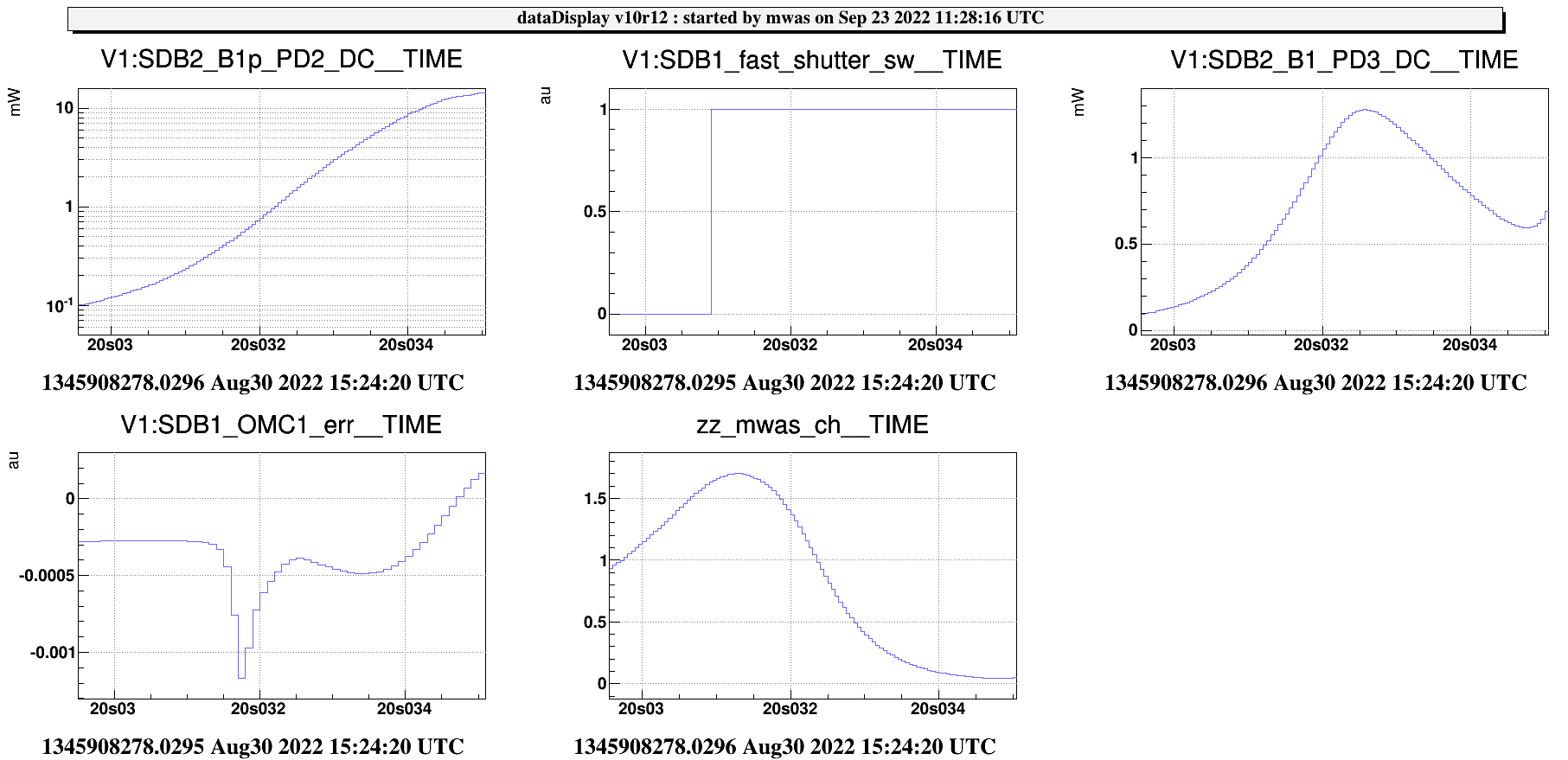
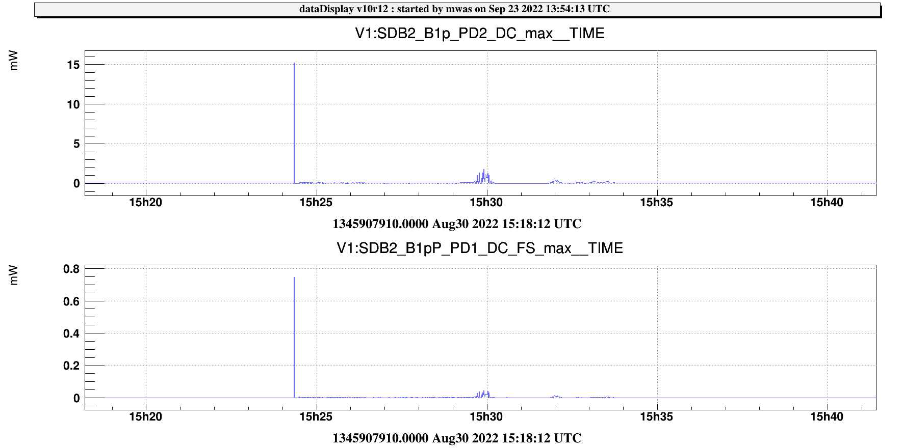
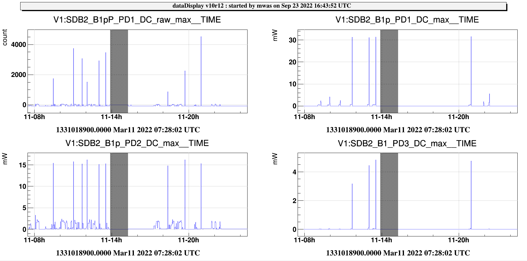
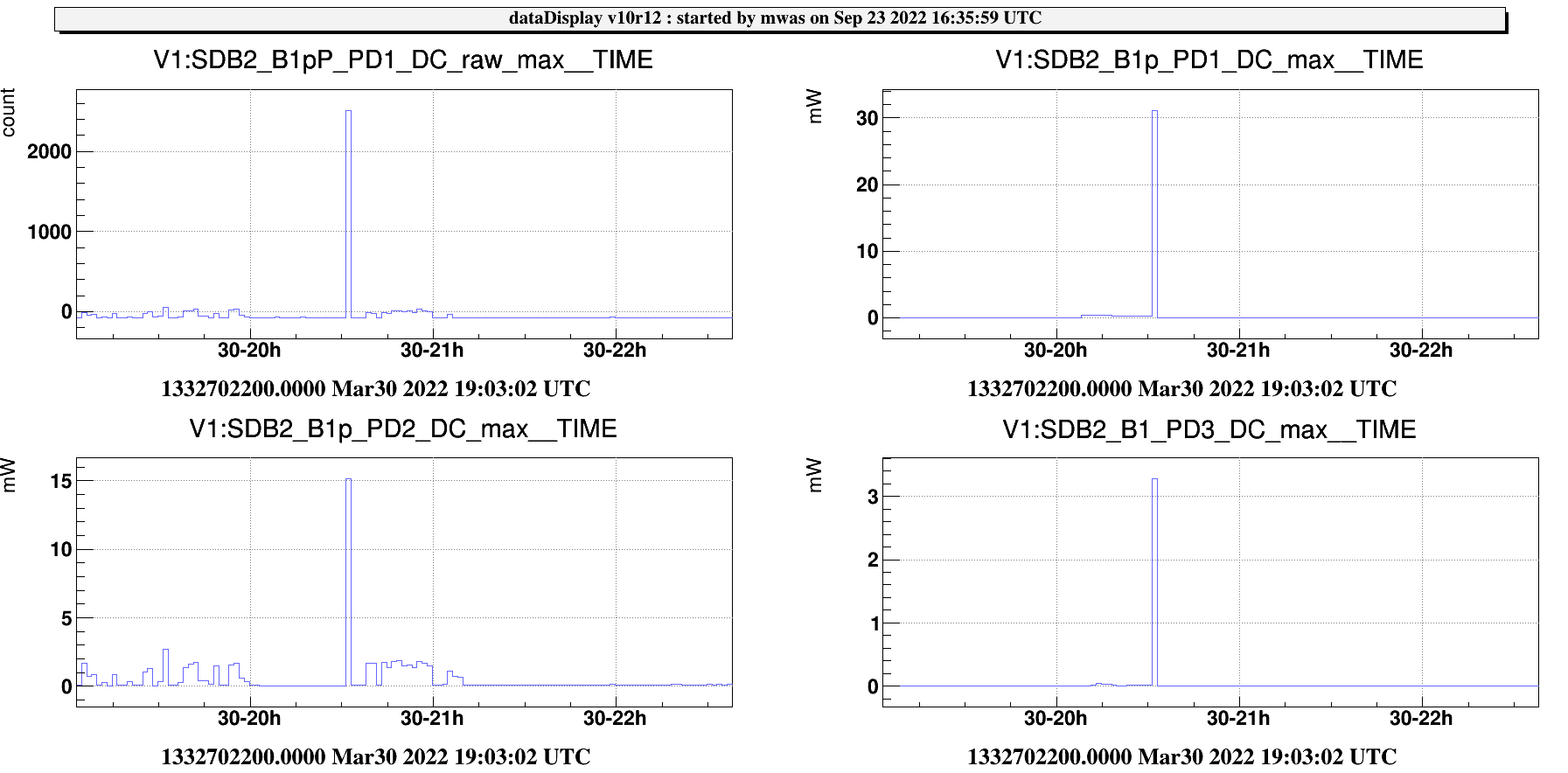
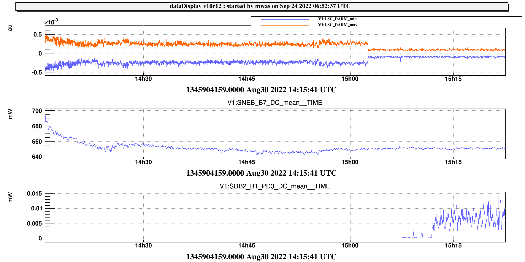
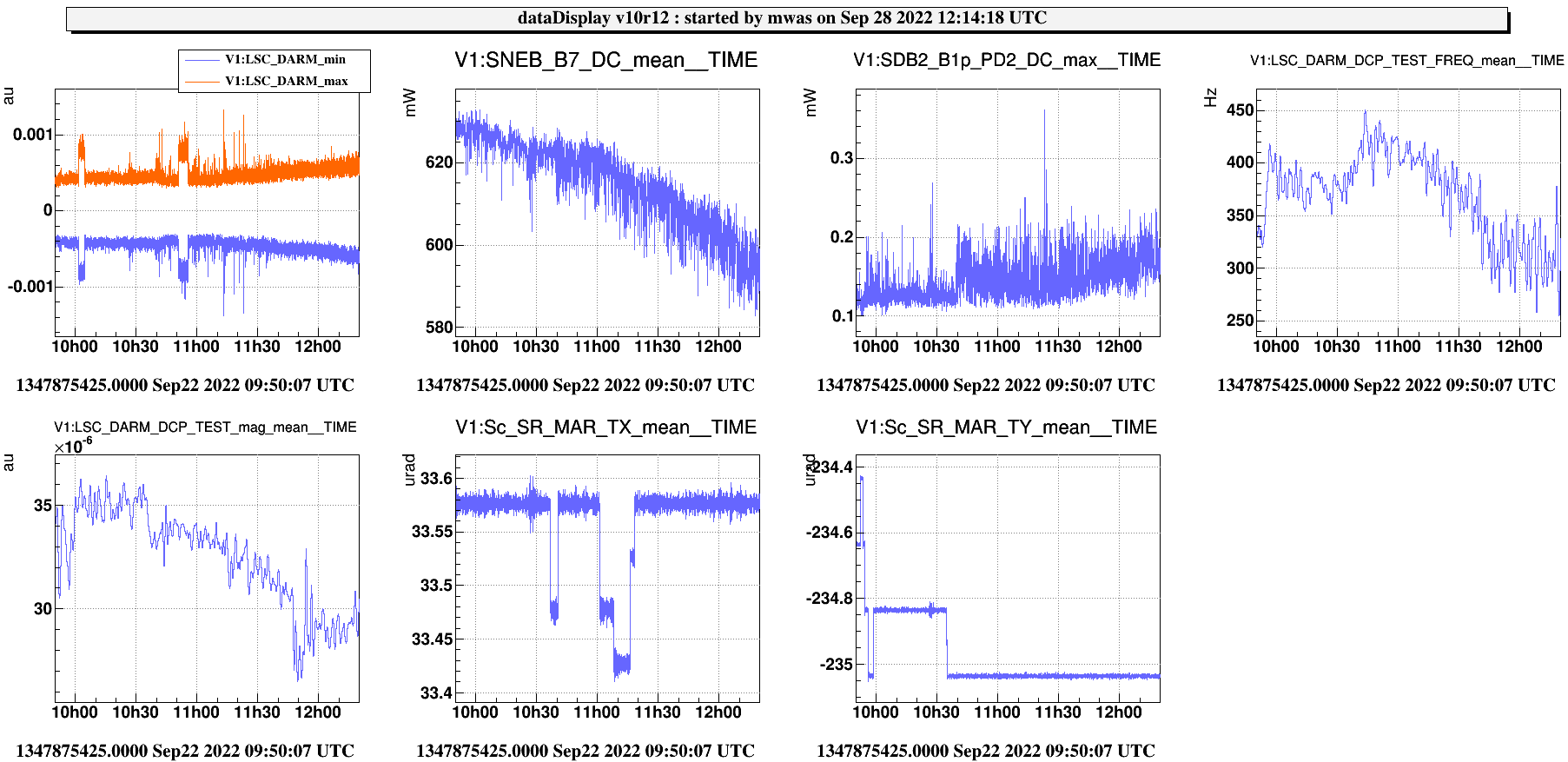
Figure 4 Looking at the trend data we can look on B1pP (the P-polarized PD), it is not saved in the raw, only in the raw full that last 7 days. But the maximum in the trend will give us a good idea of the peak. It is at 0.75mW, and the ratio of power between B1pP and B1p PD2 is a factor 0.023 when looking at other less bright flashes a few minutes later. So the peak power was ~320W on the SDB1 bench.

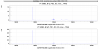
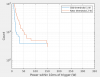
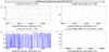
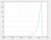
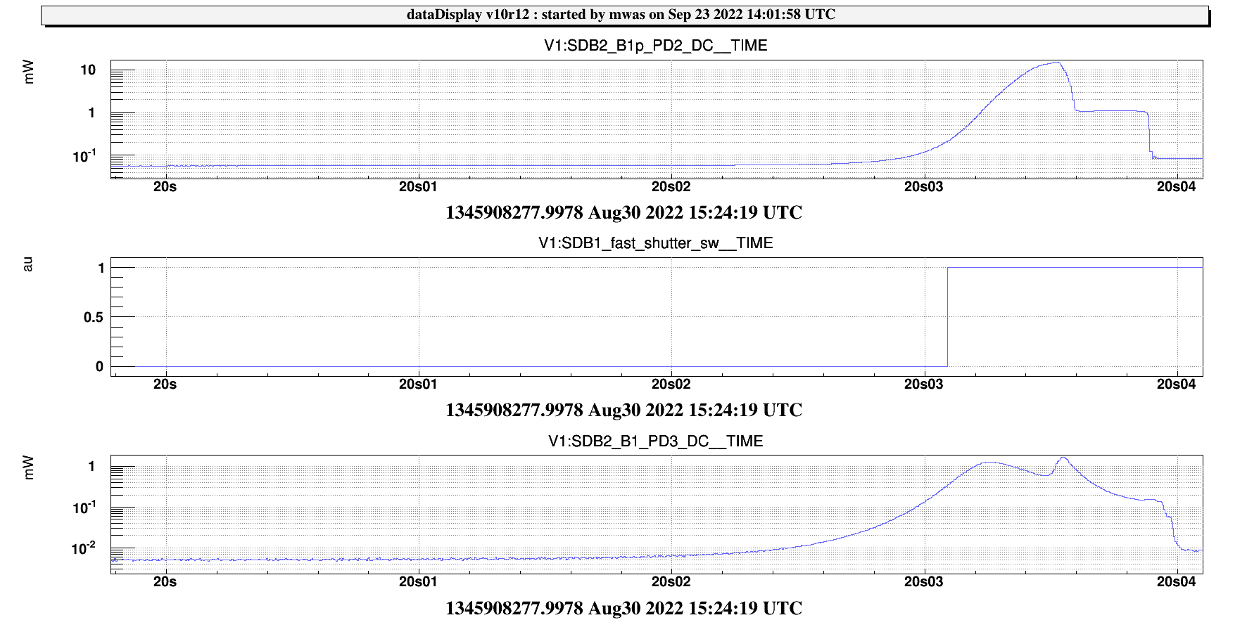
Figure 5 Looking on a log scale at B1 PD3, the loss of control start to be visible earlier on, with B1 PD3 going above 1e-2mW at 24ms. So if that was the trigger the fast shutter would have closed at 33ms, when there was 30W on the bench.

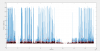
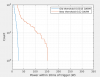
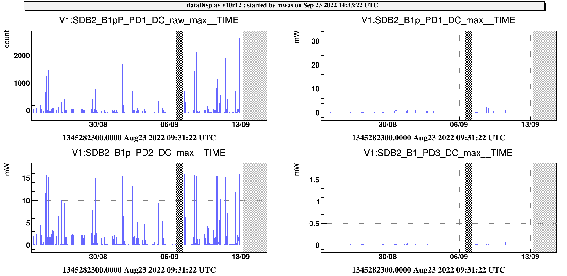
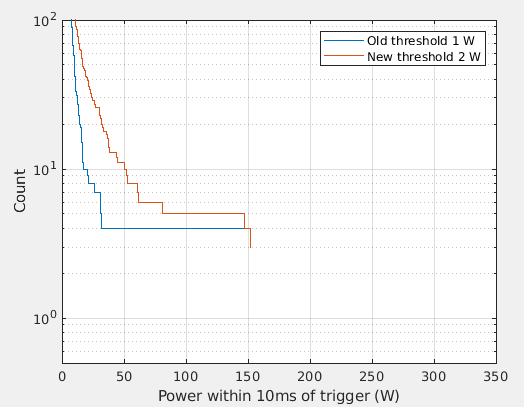
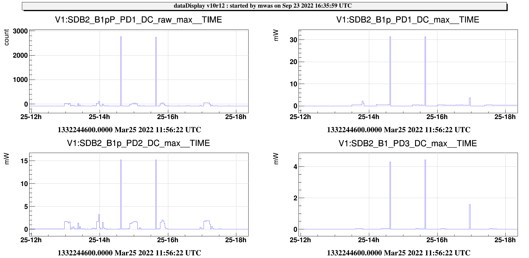
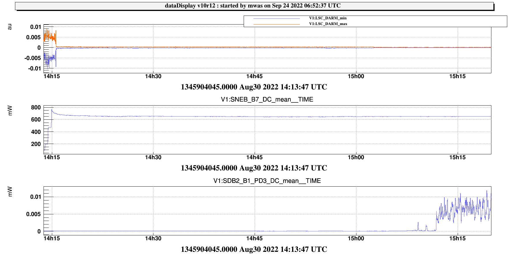
Figure 6 Looking at the trends data, B1pP is available only in terms of counts. This 320W flash corresponds to 1500 ADC counts, and the brightes flashes over a month of data seem to be 2500 counts, so 530W.

Images attached to this report
Comments to this report:
mwas - 18:47 Friday 23 September 2022 (57171) Print this report

Summary

  • The most dangerous unlocks happen in DC read-out. A lower threshold on B1p would not help with those, but a lower threshold on OMC transmission might
  • Further down the list, a threshold of 1W on SDB1 is much safer than a threshold of 2W on SDB1.
  • This year there has been already ~10 of these dangerous flashes (mostly in March), and they had up to 900W impinging on the OMC, 4W in transmission, and 1.3kW resonating inside the cavity.

I have tried to do a more systematic study of all the unlock flashes since March.

Figure 1 shows the B1p PD2 trend calibrated into power on SDB1 (mutlipied by 10e3). The red crosses correspond to what would be the maximum power if the fast shutter was triggered at 2W on the bench, and the black pluses at 1W on the bench (in CARM null up to two weeks ago the threshold was 40W on the bench if I am not mistaken. There have been a few other cases where the max power is ~150W (threshold at which the shutter of the photodiode closes, so it is just a lower limit).

Figure 2 is a histogram of these results. The brightest 4 flashes would be as dangerous with a threshold of 1W or 2W on SDB1 to trigger the fast shutter. It would have only an impact on the bulk of the distribution, having less flashes exceeding 30W, but not stopping these brightest cases.

The brightest case is the one from Aug 30. The next 3 are

Figure 3 with OMC locked, and DARM DC read-out, March 25

Figure 4 with OMC locked and DARM DC read-out, another one March 25

Figure 5 with OMC locked and DARM DC read-out, March 30

Figure 6 This one is very different, in RF read-out. A 2W threshold lets it go up to 150W, while a 1W threshold stops at 1W, as there was an oscillation for many seconds on B1p before that transient.

Figure 7 also in RF readout. A 2W threshold lets it go up to 80W, one a 1W threshold stops it at 1W, as there is a few waves in the 100ms before this flash that go slightly above 1W.

Figure 8 also in RF readout. A 2W threshold lets it go up to 60W, one a 1W threshold stops it at 1W, as there was an oscillation for many seconds on B1p before that transient.

Figure 9, 10 and 11 Looking back at the trend data of B1pP. The flashes in March reported above had 2500 counts, which correspond to ~500W on SDB1, and there was even a few more earlier in March, that had 4500 counts, so about 900W on SDB1.

/users/mwas/OMC/OMCflashSafety_20220923/flashAnalysis.m

Images attached to this comment
mwas - 9:53 Saturday 24 September 2022 (57178) Print this report

Figure 1-4 show the 4 examples of powerful flashes in OMC read-out. In all cases LSC_DARM moves beyond the +/-0.001 range more than 10ms before the bright part of the flash. So this could be an excellent trigger for the OMC fast shutter.

Figure 5 shows an example CARM null lock, and after a few minutes LSC_DARM is well within +/-0.001. Once the dither lines are reduced to prepare for OMC lock, there is even a factor 10 of margin with fluctuations staying within +/-1e-4 on LSC_DARM.

Images attached to this comment
mwas - 13:45 Saturday 24 September 2022 (57180) Print this report

Figure 1 and 2 shows two lock acquisition, DARM stays within +/-0.02 during the last two steps of CARM offset reduction. This could be a threshold to use to trigger the fast shutter during the lock acquisition end stages when there can be powerful flashes.

Figure 3, 4 and 5 shows the most dangerous DARM RF unlocks in the last 6 months. In all cases a +/-0.02 threshold on DARM would have allowed to close the fast shutter in 10ms, well before the bright flash arrives on SDB1.


Images attached to this comment
mwas - 10:11 Monday 26 September 2022 (57190) Print this report

This is a more systematic check of using DARM absolute value for triggering the fast shutter over 6 months of data.

Figure 1 shows the histogram of the power on SDB1, using a 0.02 and 0.0015 threshold on DARM. The 0.0015 threshold cuts the max power to 20W. With an 0.02 threshold there is a dozen of flashes that go beyond 100W, and a few that arrive at the PD saturation of 150W (so could be brighter than that).

Figure 2 shows that the red cross (threshold of 0.02) in most cases are well below the peak recorded power (blue line), so a threshold of 0.02 on DARM would be much better than what we do right now during lock acqusition

Figure 3 and 4 are one of the flashes that is not stopped by the 0.02 threshold. Figure 3 is B1p PD2, which almost reaches the PD saturation of 15mW, and the trigger on DARM of 0.02 (figure 4), would be due to the glitch, which happens 10ms before the peak power on B1p PD2, so marginally too late.

Images attached to this comment
mwas - 14:37 Wednesday 28 September 2022 (57224) Print this report

Figure 1 shows a time when SR was well aligned (high DCP frequency but also high B1p fluctuations). During that time DARM stays within +/-1.5e-3, so the trigger on the fast shutter at 1.5e-3 could work well in these conditions. There are periods of a few minutes where DARM is at +/-1e-3, I expect this is during DARM noise injection to check the DCP. There are a few glitches on DARM that get very close to +/-1.5e-3.

Images attached to this comment
Search Help
×

Warning

×