Summary
- Lowering the CHRoCC power seems to improve the 56MHz mode matching by 40% for the USB and LSB from the point of view of the OMC
- The mode shape is very bad in any case with ~30% of order 1 mode and ~50% of order 2 mode, and many bright higher order modes
I have looked at the scans for 3 powers of the PR CHRoCC. Note that the USB (as described by the phase camera) is at lower OMC temperature, so that is why it appears first and is marked at negative frequency in the figures below.
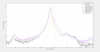
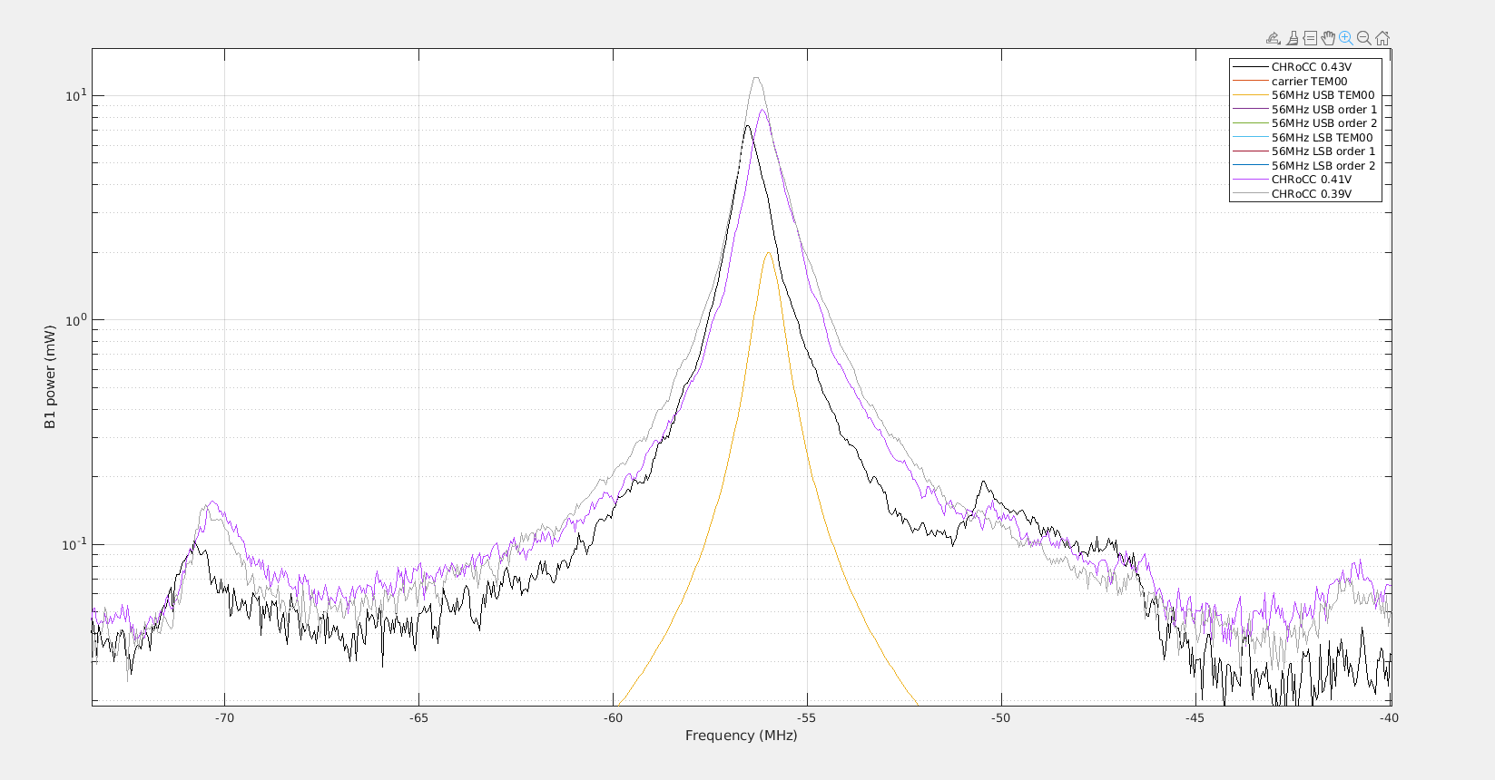
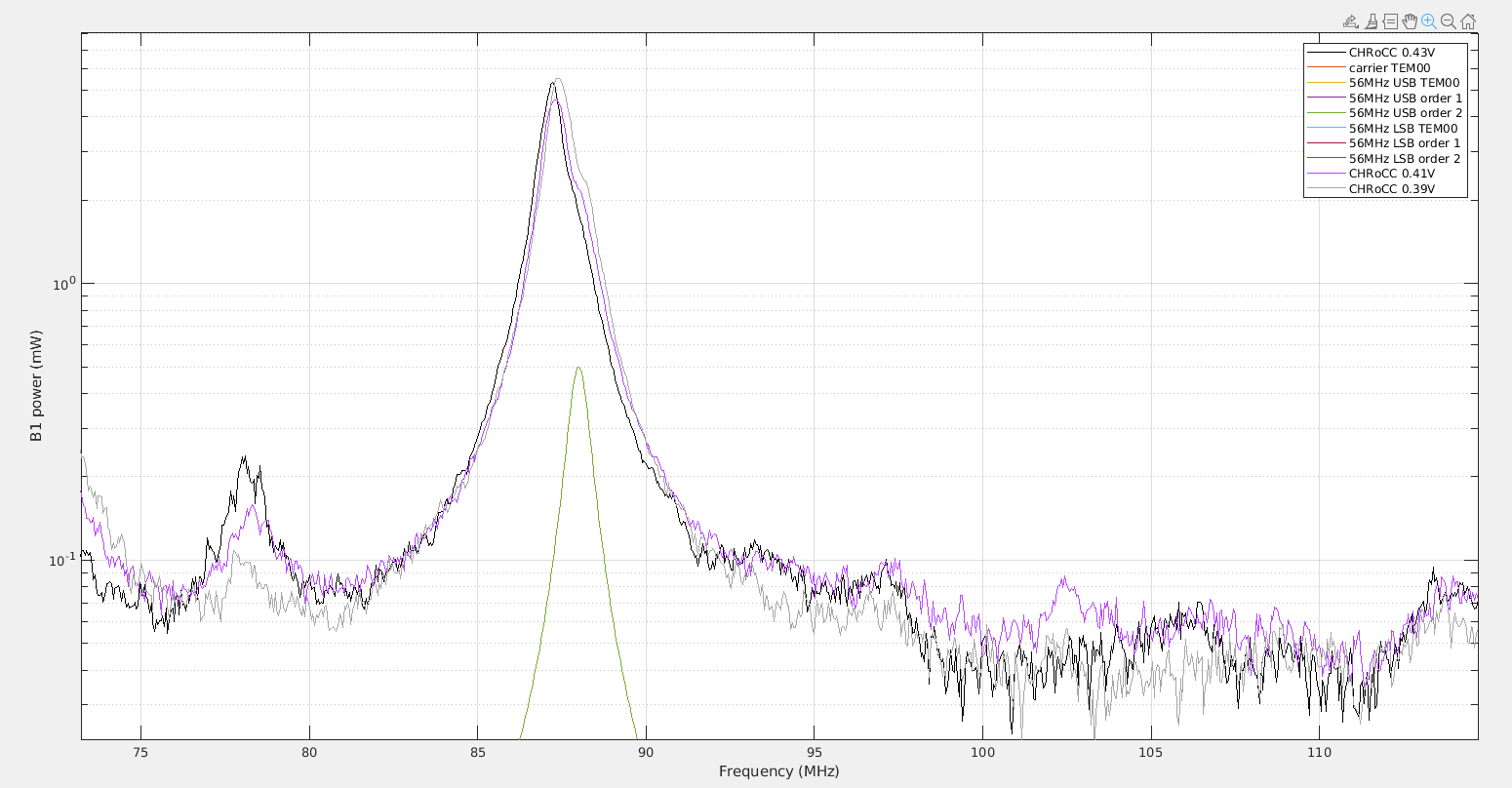
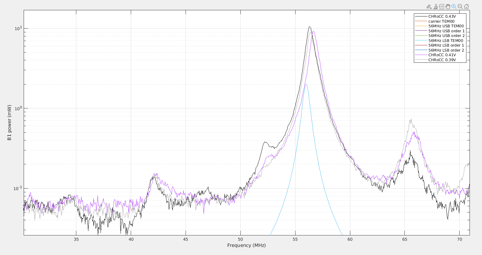
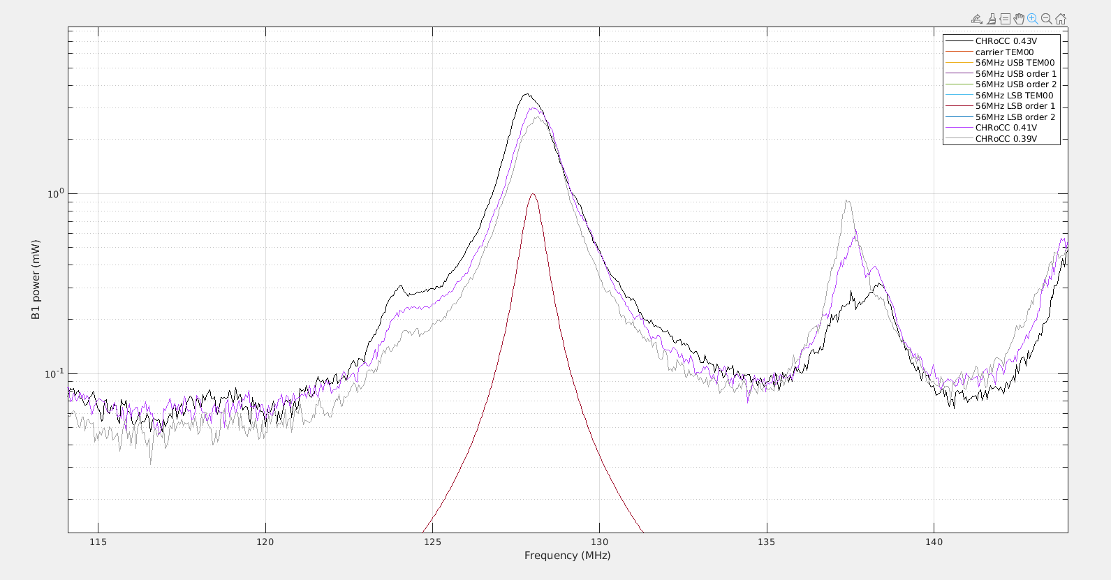
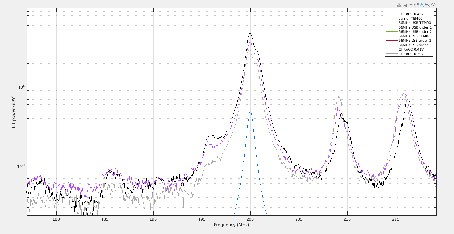
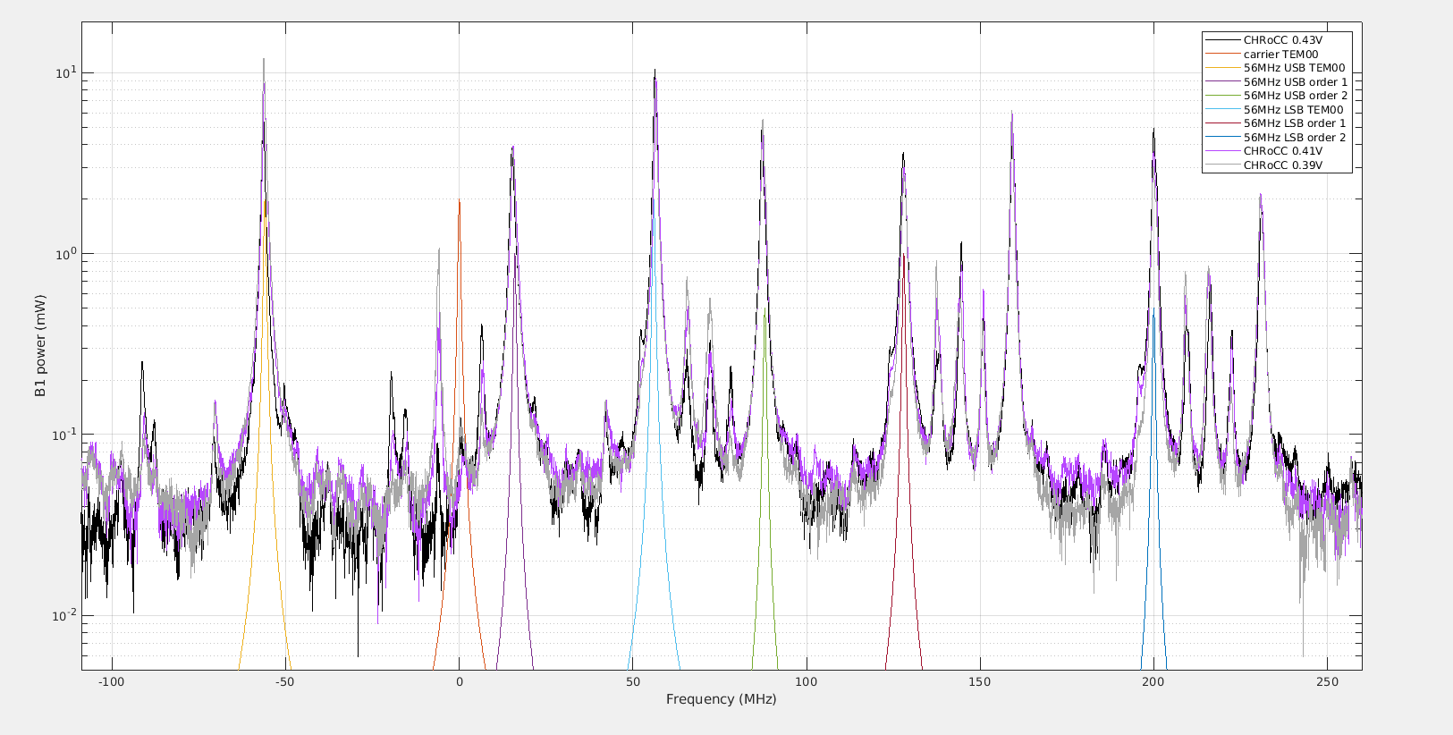
Figure 7 is the overview, with the time roughly rescaled into MHz. The black line is for 0.43V, purple for 0.41V and grey for 0.39V. Also the position of the LSB/USB order 0, 1 and 2 are marked as a guide for the eye. The order mode has roughly 1/3 of the power of the TEM00, and the order 2 mode has roughly 1/2 of the power of the TEM00. This is a lot of misalignment and mode-mismatch. But I don't know what our expectation should be. Note that there is quite of higher order modes to. For example the USB order 3 mode has also 50% of the power of the TEM00.
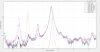
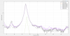
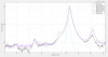
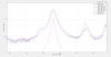
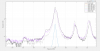
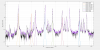
Figure 1, 2 and 3 show respectively the oder 0, 1 and 2 mode for the 56MHz USB. Figure 4, 5 and 6 show the order 0, 1 and 2 mode for the 56MHz LSB.
The USB TEM00 seems to increase in power by ~20% for each step of reduction in CHRoCC power. The order 1 and 2 modes stay roughly the same, changing by less than 10%.
The LSB TEM00 stays the same within 10%. While the order 1 mode is reduced by 30%, and the order 2 mode is reduced by 40%.
So for both the 56MHz LSB and USB the mode shape improves as the CHRoCC power is reduced, as the ratio of TEM00 to order 1 and 2 modes is improving by 40%. The balancing of the sideband TEM00 remains roughly the same but changes signs. For 0.43V, the USB TEM00 was 30% lower than the LSB TEM00, while at 0.39V the USB TEM00 is 30% more powerful than the LSB TEM00.
When I look at the mode shapes during the scan at 0.43V the USB order 1 mode is ~80% a vertical misalignment, and the order 2 mode is completely vertical. For the LSB the order 1 mode is also ~80% vertical, while the order 2 mode is unclear as the camera shows a vertical mode, then a cross shaped mode, then a bull-eye mode, and there is only one image per second, so it is unclear what is corresponding to the peak, the order 2 mode in the time series does look like it is double with one peak half the size of the other, so it is reasonable to think that the horizontal and vertical order 2 mode contribute, with power ratio of a factor 2 between them.
When I look at the scan at 0.39V. The USB shows the same pattern, and the LSB as well, with also an ambiguous order 2 mode shape, that happens to be the brightesst for the horizontal order 2 mode, but this is somewhat random due to the sampling of 1Hz for the camera image.
Code used for these figures is in /users/mwas/OMC/OMC_scan_20220812