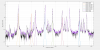
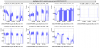
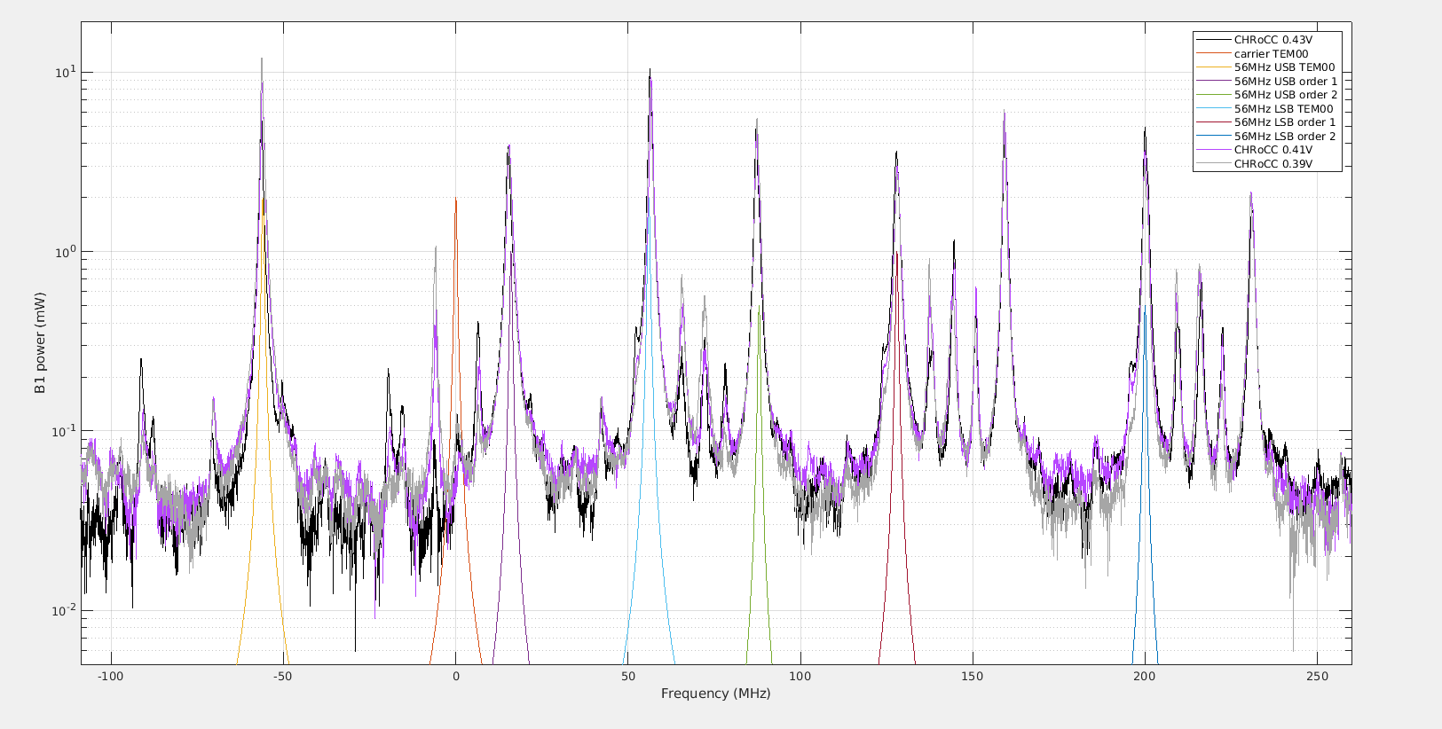
Explore different CHRoCC settings and to study the matching of the sidebands in the CITF.
Most of the data analysis has already been explained in the entry by Cabrita (56736).
Additionally, at 14:00 UTC the thermal transient for a third point finished, and we repeated the procedure for the matching scan. The following table shows the UTC of each scan over the course of the shift.
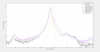
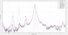
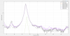
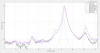
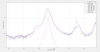
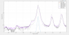
For the CITF scan, the CARM offset was swept between 3000 Hz and 32250 Hz with the CITF locked (56737).
| CHRoCC tension | Long Cavities FSR + Matching Scan | CITF Scan | OMC Scan | Notes |
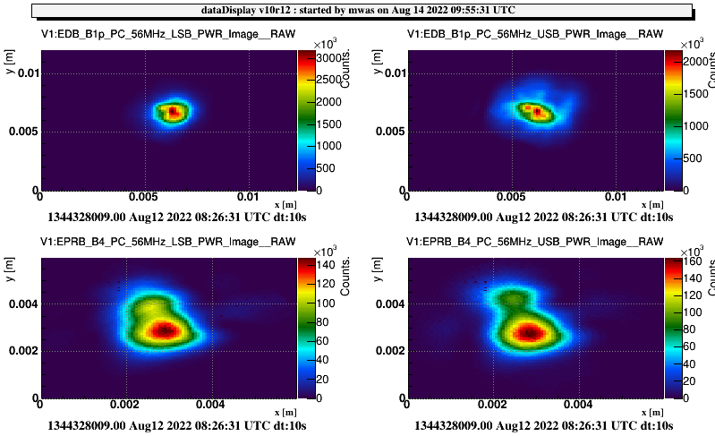
| 0.43 V | UTC:06:58:00+1080s | UTC:08:09:00+300s | UTC:08:26:00+1200s | |
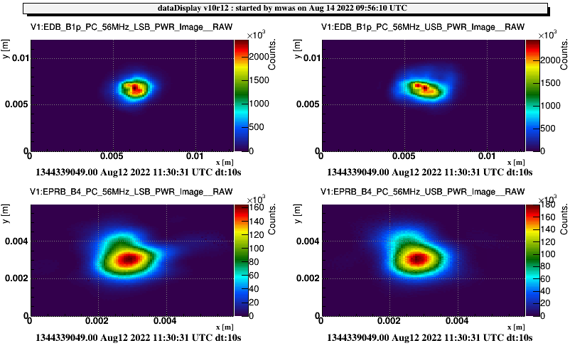
| 0.41 V | UTC:12:04:00+1320s | UTC:11:03:30+900s | UTC:11:33:00+1200s | the CITF unlocked during the "coming back" part of the CARM SET scans. |
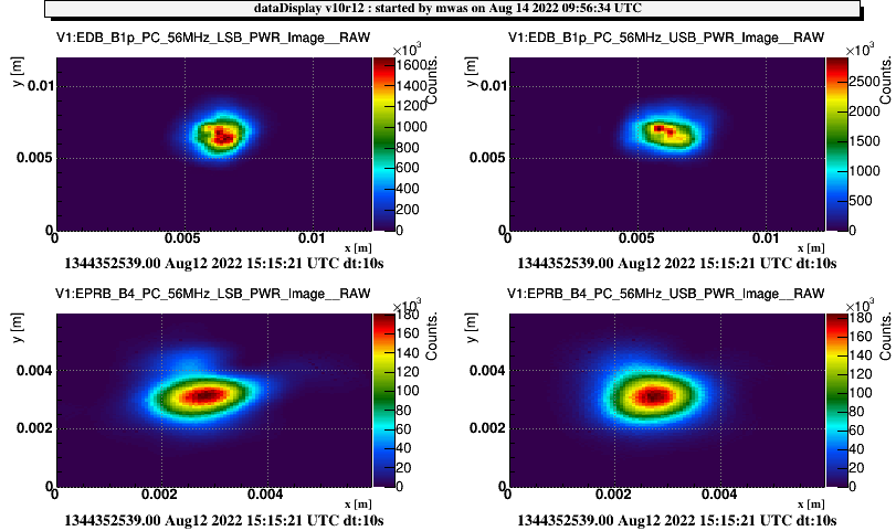
| 0.39 V | UTC:14:11:00+1020s | UTC:15:42:40+100s | UTC:15:06:00+1200s | We have one full cycle but the CITF is very critical during the second and unlocked twice right at the end of the ramp up. |
While the CITF unlocked repeatedly during the "return" part of each ramp for 0.41 V, we decided that the data gathered during the first half of each ramp were sufficient and, given the long time taken by each measurement, it was more important to move on the the next point than to try and make the CITF stay locked. With this idea in mind, from the ISC point of view, no significant change to the lock parameters were made over the course of the shift.
For the third CITF scan, we were able to complete one scan at 0.39 V but lost lock ramping up on the second. This point will be studied further during tomorrow's shift.
We left the ITF in single bounce.