Reports 1-1 of 1 Clear search Modify search
Detector Operation (Operations Report)
amagazzu - 17:18 Saturday 13 August 2022 (56745) Print this report
Operator Report - Daily shift

The shift was dedicated to the planned ISC/OSD/DET activity (PRC matching with CHRoCC fine-tuning, scan of arm cavities and OMC in CITF), carried out by Casanueva, Spinicelli, Guo.
During the first part of the shift, we finished the measurements started Yesterday morning, exploring the previous PR CHoRCC value (V_DAC at 0.39 V). Here is the timetable of the measurements performed;

From 7:00 UTC to 7:25 UTC - CITF Scans;
7:28 UTC - 5 minutes of CITF locked;
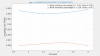
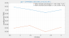
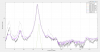
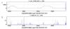
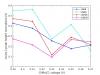
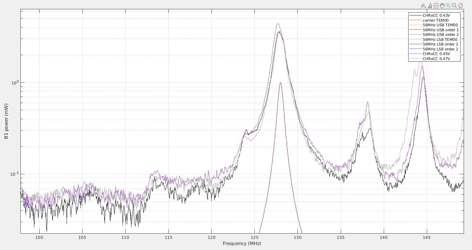
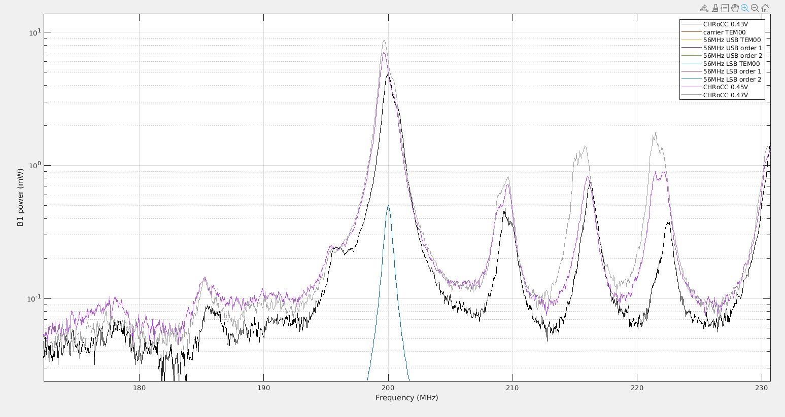
7:45 UTC - Cavities Scan Matching, command SCAN_TEMs_TOT(1) (see attached plot #1);

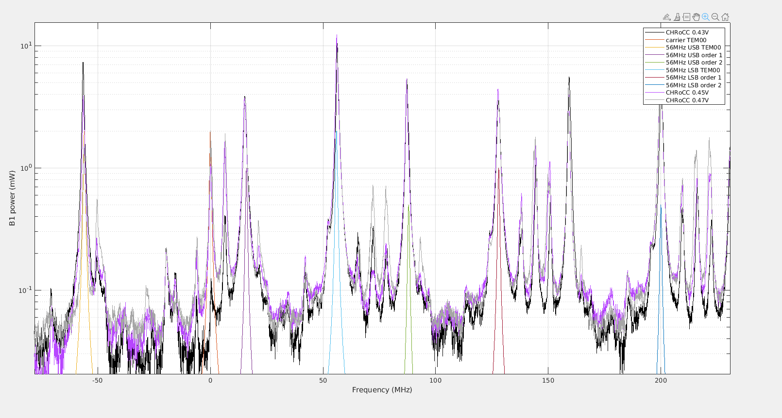
At 7:59 UTC we changed the DAC_V of PR CHRoCC in the opposite direction, from 0.39 to 0.45 V. We waited 90 minutes and then proceed with the measurements:

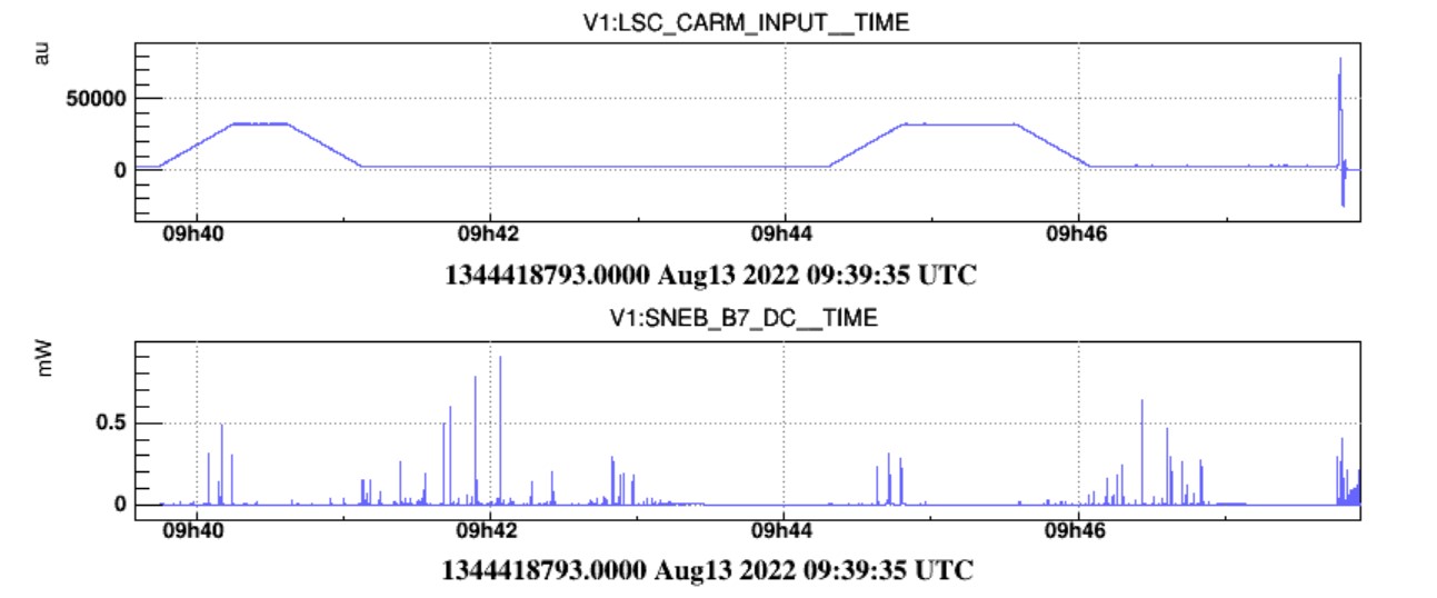
9:39 UTC - CITF Scan;
10:35 UTC - Attempted OMC Scan, it was followed by an unlock a few seconds after starting;
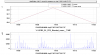
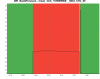
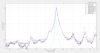
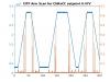
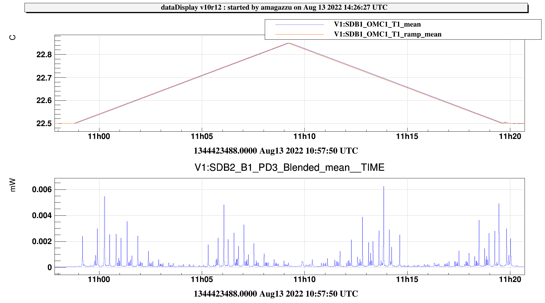
10:58 UTC - OMC Scan (see plot #2). At 11:11:50 we noticed a spike in the Powers of the CITF and a change in its behavior.
11:33 UTC - Free Spectral Range Scan while in LOCKED_ARMS_BEATING, command CARM_SET_scan_FSR(6);
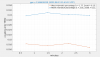
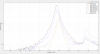
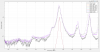
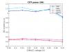
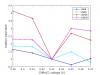
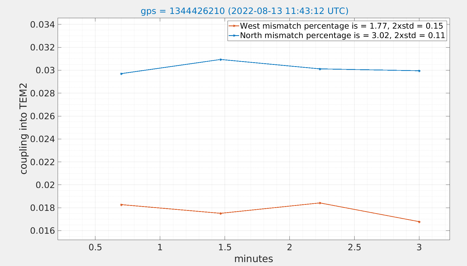
11:38 UTC - SCAN_TEMs(1) (see plot #3);

At 11:51 UTC we changed the V_DAC of PR CHoRCC, from 0.45 to 0.47 V. We waited 90 minutes and then performed the last sets of measurements.

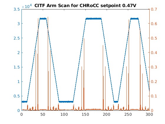
13:25 UTC - CITF Scan;
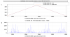
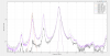
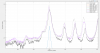
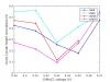
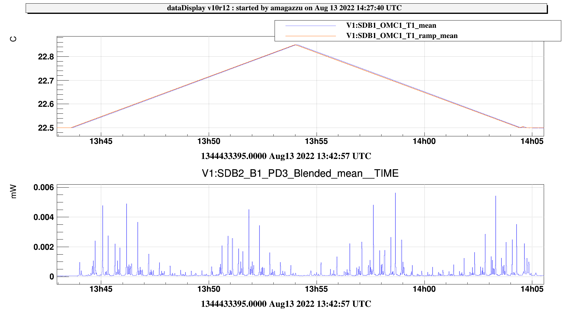
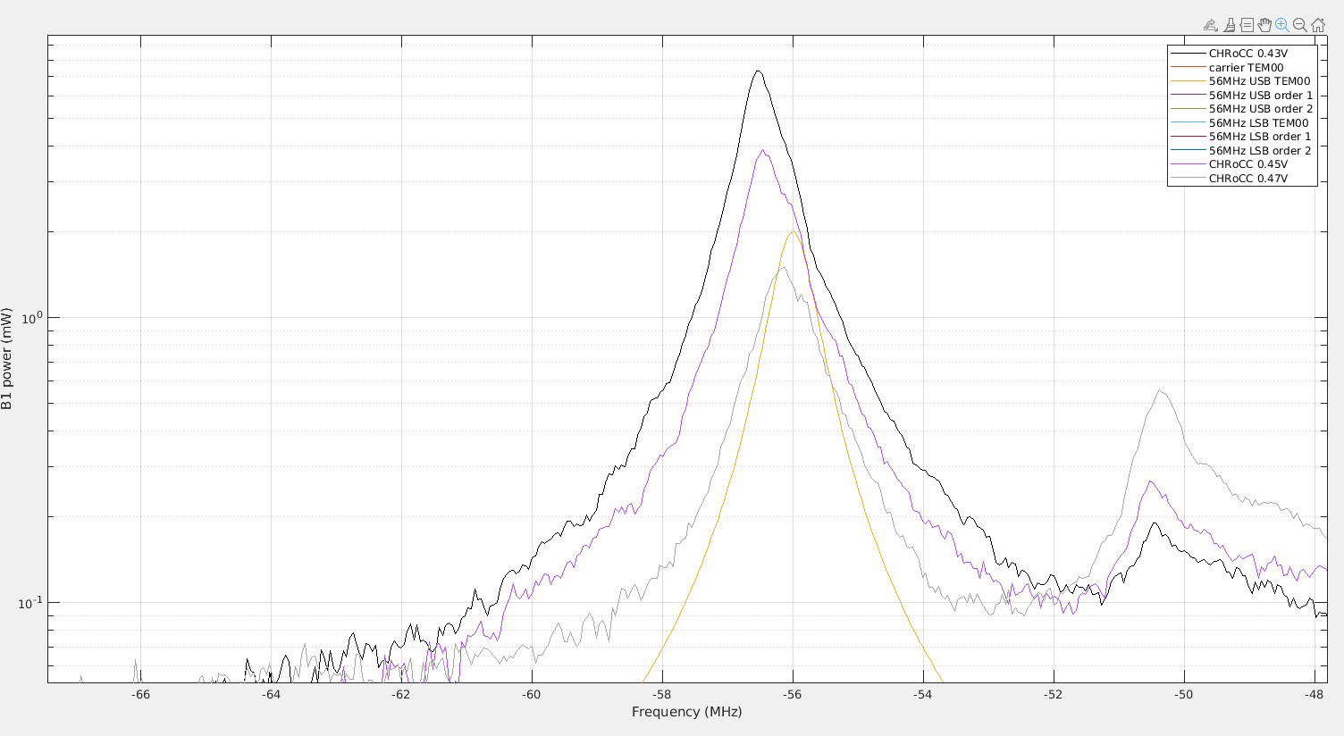
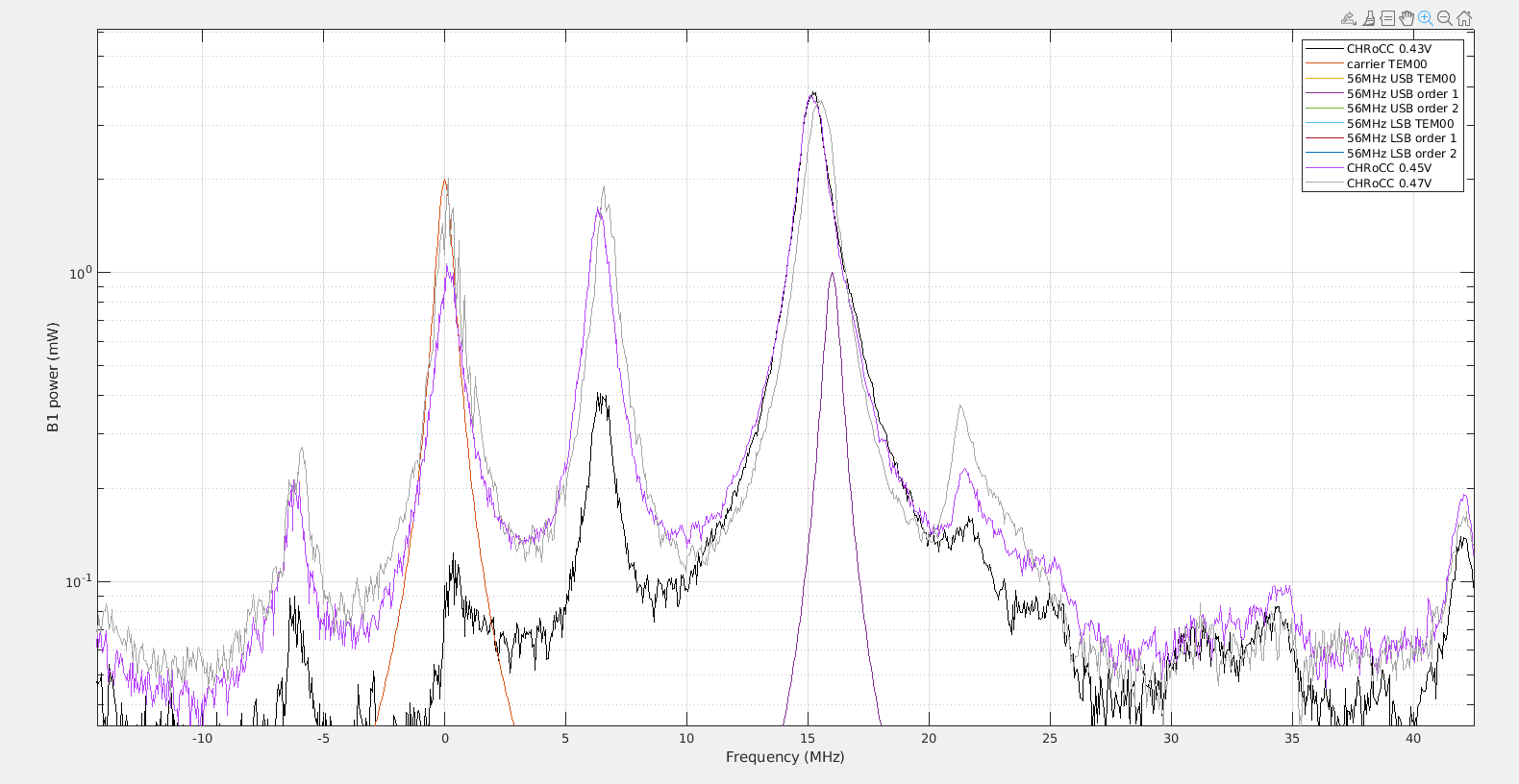
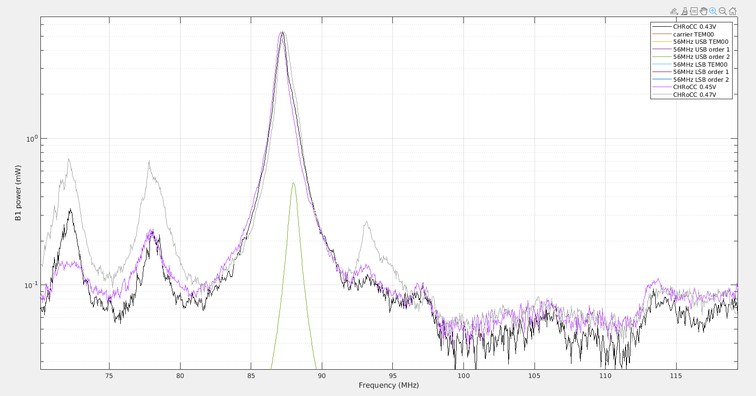
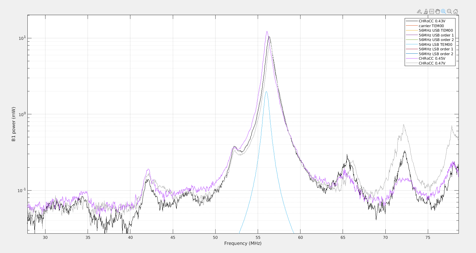
13:43 UTC - OMC Scan (see plot #4);
14:14 UTC - CARM_SET_scan_FSR(6);
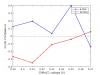
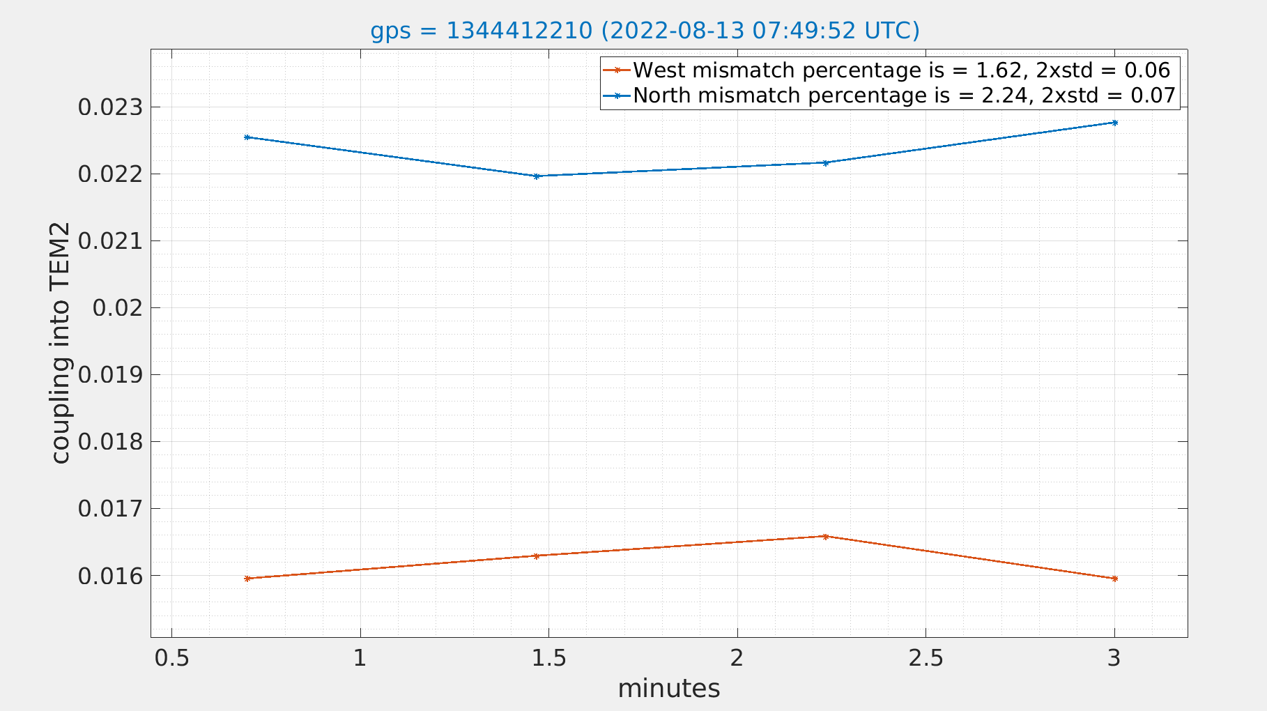
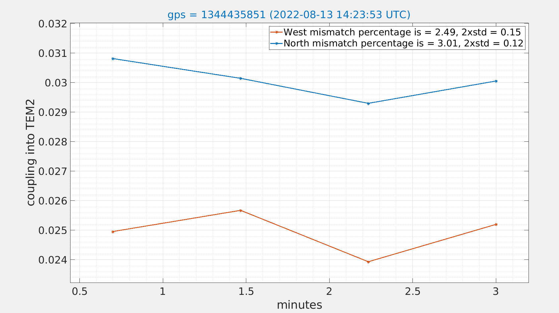
14:19 UTC - SCAN_TEMs_TOT(1) (see attached plot #5);

At 14:33 UTC, as agreed with the Weekly Coordinator, I set back the Voltage to 0.43 V as a starting point for tomorrow's shift.

Infrared cavities left locked.

Sub-system reports

Vacuum
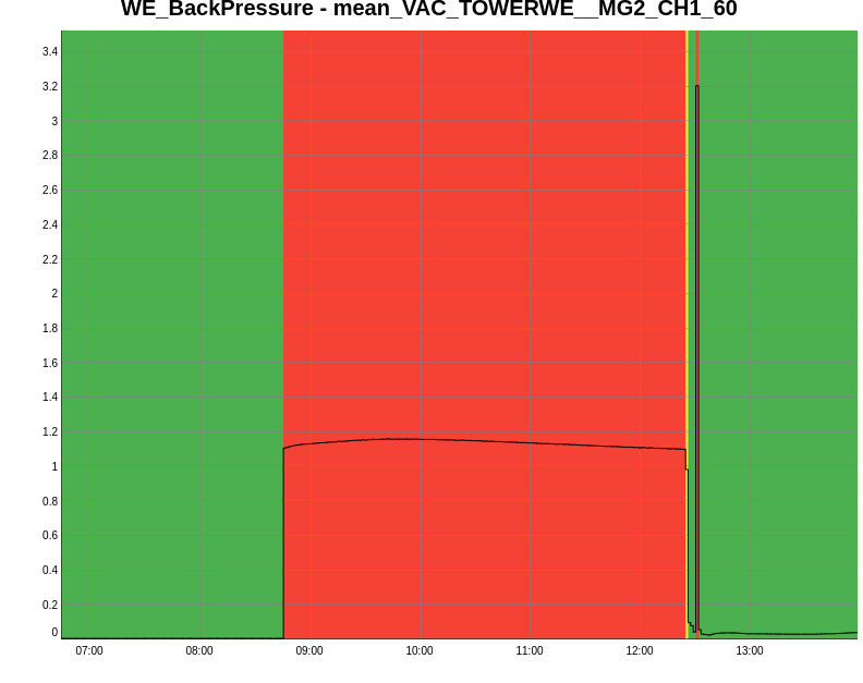
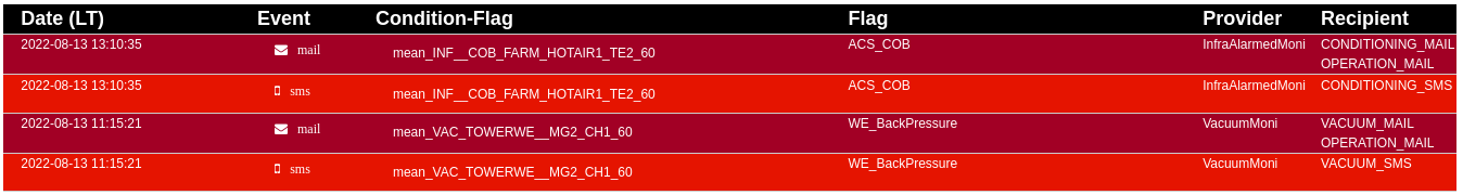
At 8:45 UTC the value of the flag mean_VAC_TOWERWE__MG2_CH1_60 suddenly increased (see attached plot #6). Francescon came on site and, at around 12:30 UTC, switched on a supplementary P61 Pump in the WE Building. The value returned to its threshold, further investigation will be performed next week.

Images attached to this report
Comments to this report:
mwas - 22:55 Saturday 13 August 2022 (56749) Print this report

I have looked at these two OMC scans at 0.45V and 0.47V on the CHRoCC and compared to the 0.43V case from yesterday as a reference value. This complements the analysis of the OMC scans from yesterday

Figure 1 shows the overview. Figure 2, 3 and 4 shows the USB order 0, 1 and 2 modes. While Figure 5, 6 and 7, show the LSB order 0, 1 and 2 modes.

There is the same pattern as observed yesterday, increasing the CHRoCC power reduces the USB TEM00 power, by a factor 5. While the order 1 and 2 modes stay about the same within 10%. For the LSB the order 0 and 1 mode remain the same, while the order 2 mode keeps increasing by almost a factor 2 when reaching 0.47V.

Images attached to this comment
cabrita - 21:23 Tuesday 16 August 2022 (56759) Print this report

I looked at the data for Friday and Saturday shifts, whith changing CHRoCC values from 0.39V to 0.47V. First, when looking at the plots it is important to notice that for the 0.45V data point half of the scans weren't usable since there was no signal on the downward ramp, and the signal that was obtained was changing quite a lot, see Fig. 1. For the 0.47V datapoint no 56 MHz LSB was showing up in the scan, so there is no data for it (Fig. 2).

Fig. 3 shows the reference power in CITF as seen by the B4 phase camera, same power that was used to normalize the mode order 2 power during the CITF arm scans.

Fig. 4 shows the normalized peak height values for each sideband HOM2 for each CHRoCC datapoint.

Fig. 5 shows the relative mode mismatch, computed in relation to the central point for 0.43V.

Fig. 6 shows the sideband imbalance for mode order 2 (computed from Fig. 4).

Conclusion: The apparent point of lower mismatch, 0.43 V except for LSB 6MHz (at 0.45V) does not coincide with the most power in CITF. In simulation (ideal case), only the 56 MHz had mode 2 imbalance around the optimal value, here we see it as well for the 6 MHz, albeit in smaller amount. Additionally, in simulation the mode imbalance of 56 MHz the imbalance sign flips around the modematched value, working as a kind of error signal, however, here due to the difficulties with 0.45V and 0.47V data points, we can't be sure where is the 0 crossing of the imbalance.

EDIT: Forgot to mention only the North Arm was used for this analysis, since it is difficult to interpret the signal from the west arm, see: https://logbook.virgo-gw.eu/virgo/?r=56736

Images attached to this comment
cabrita - 19:32 Wednesday 17 August 2022 (56768) Print this report

Julia pointed out a set of scans that I had missed for the 0.47V CHRoCC setpoint that also have data for the LSB 56 MHz. I re-did the analysis with the new data, I also fixed a bug in the calculation of the 56 MHz values at 0.47V setpoint.

We can now see a 0 crossing in the sideband mode 2 imbalance, even though there is a big uncertainty for the 56 MHz values at CHRoCC 0.45V because only two scans were available and the values vary quite a bit.

Images attached to this comment
Search Help
×

Warning

×