Triggered by a question from Romain Gouaty, here some little clarification about the IPC2 current setting as for the transmission of the beam to the ITF (and back).
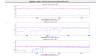
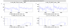
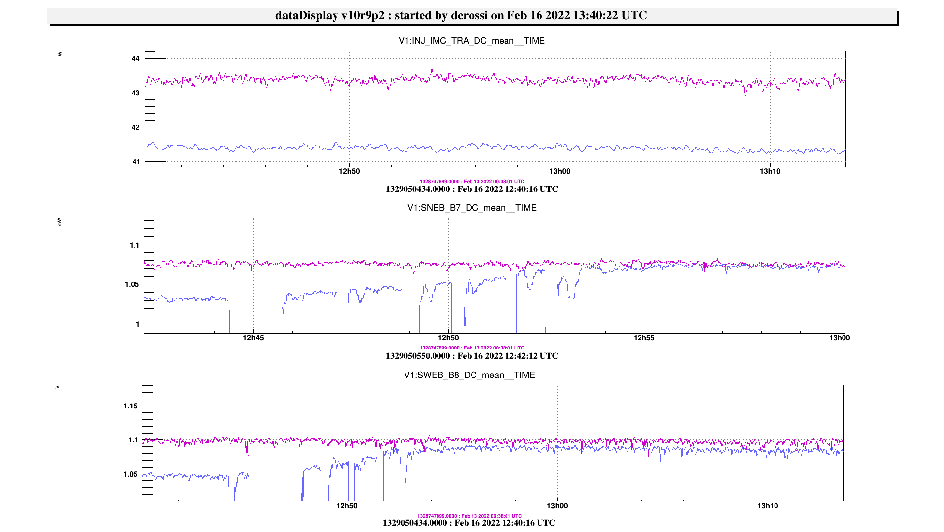
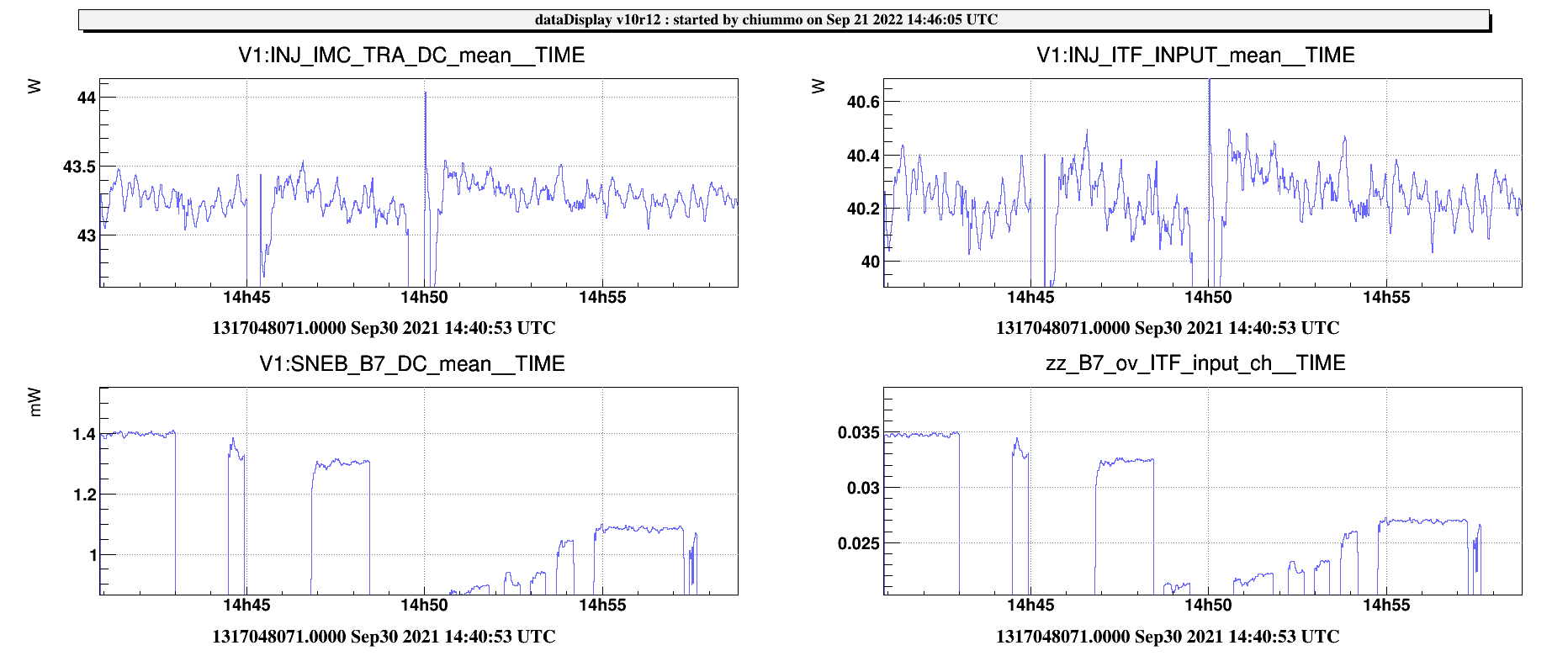
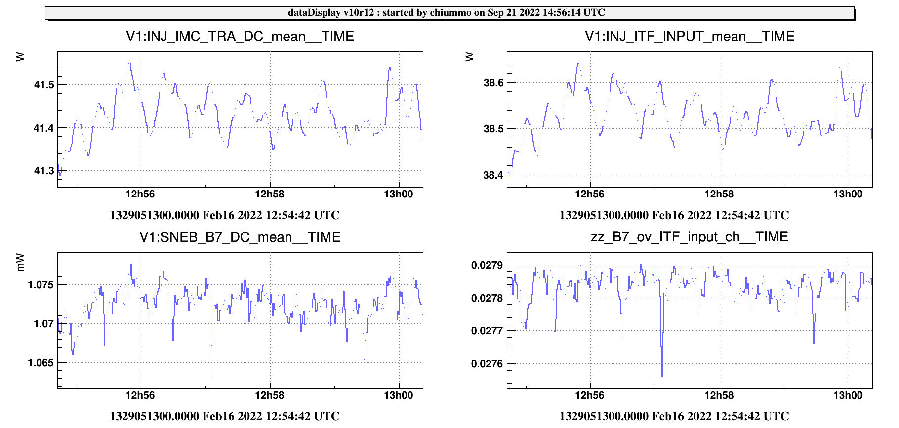
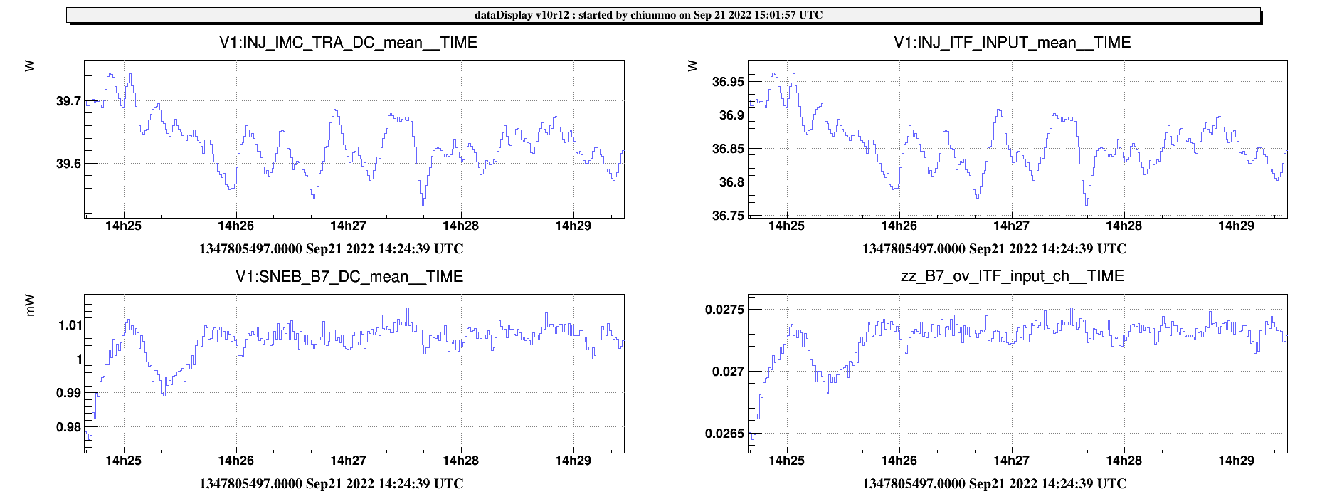
Back in September 2021, we tuned the transmission of IPC2 from its maximum down to a value which ensured around 33W of input power to the PR mirror. This was done by looking at the power transmitted by the arm cavities (since the monitoring sensors we have in INJ are all upstream wrt IPC2 action). In the first plot, we have IMC_TRA_DC which is the power transmitted by the IMC cavity, and ITF_Input which is the channel calibrated from IMC_TRA by taking into account the known losses (7.5%) when the IPC2 is at the maximum of the trasmission. The tuning of IPC2 does not change these channels, while it decreases the power transmitted by the arm cavity (SNEB_B7_DC). We had a first adjustment of IPC2 on Sep 30 2021 and then a slight retuning on Feb 16 2022.
| IMC_TRA_DC (W) | ITF_Input (W) | B7 (mW) | date | IPC2_T |
| 43.4 | 40.2 | 1.4 | 30 Sep '21 (before) | MAX |
| 43.4 | 40.2 | 1.08 | 30 Sep '21 (after) | 0.77 |
| 41.45 | 38.55 | 1.073 | 16 Feb '22 (after) | 0.80 |
| 39.6 | 36.85 | 1.01 | 21 Sep '22 (no change) | 0.79 |
This estimate of the IPC2 Transmittivity depends on the matching conditions, so it is accurate up to around 1%.
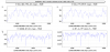
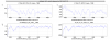
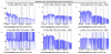
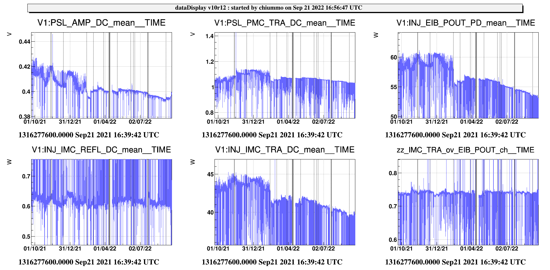
The decrease of the power delivered by the Injection is mostly due to the drift of the amplifier (see plot 4, 1 year of Injection powers).
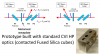
To be noticed that the effect of the attenuation by IPC2 occurs both on the beam sent to the ITF and on the beam backreflected by the PR. A figure taken from from Eric's presentation VIR-0094A-13 illustrates the issue, basically depending on the fact that there is a half-wavelength plate in between two polarizers. So the overall transmission of the backreflected beam from the IMC_TRA to SIB2 (to be added to all the other losses) is (IPC2_T)^2.