In addition to these very interesting finding one can notice a few more things
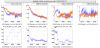
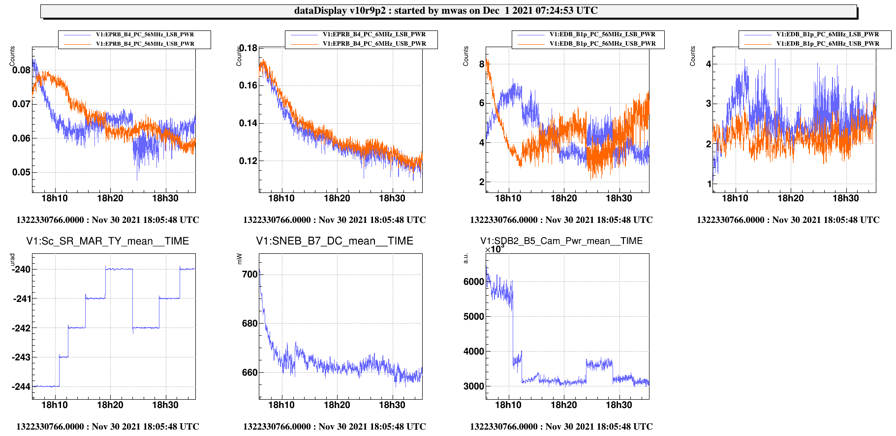
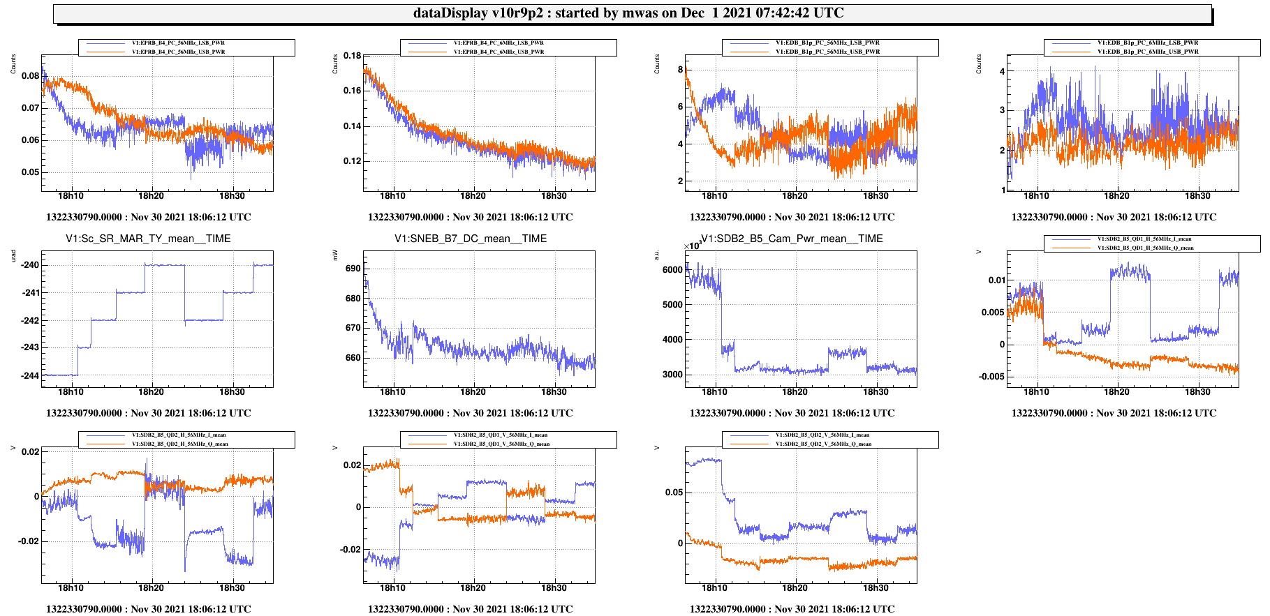
Fig 1. The SR alignment has an impact on the balancing of the 56MHz sideband (as seeon the B4 and B1p phase camera), but no visible impact on the 6MHz sideband. This is expected as the 6MHz sideband should not enter the SR cavity. The power on the B5 camera is reduced at the same time as the steps in SR TY alignment are done.
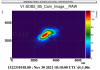
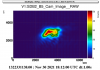
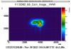
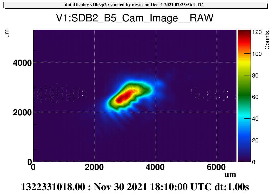
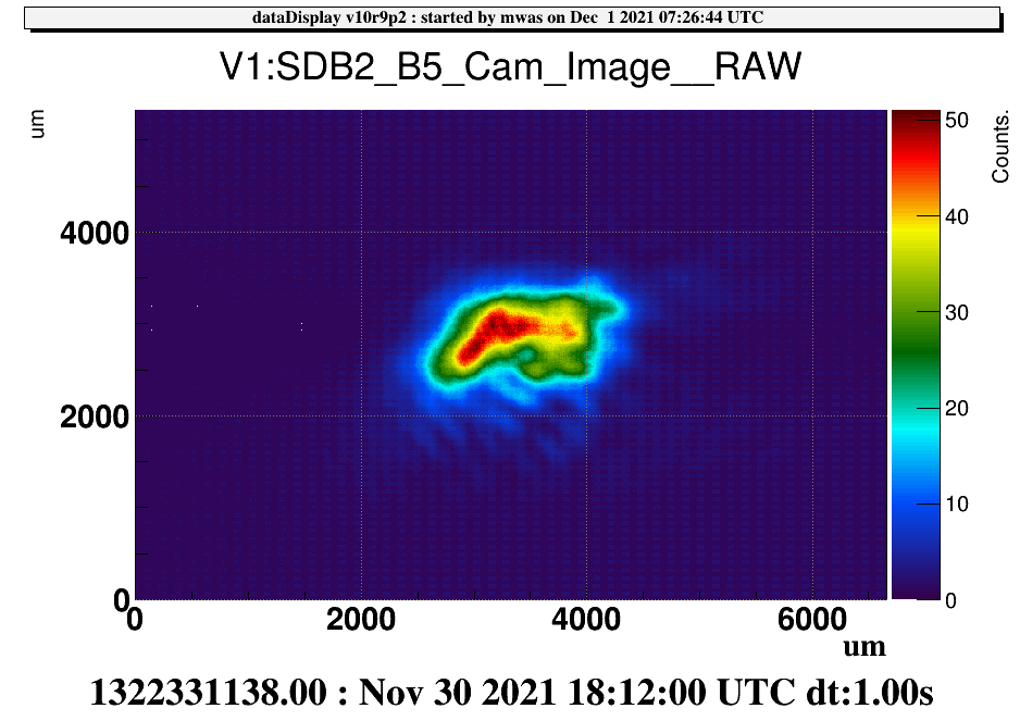
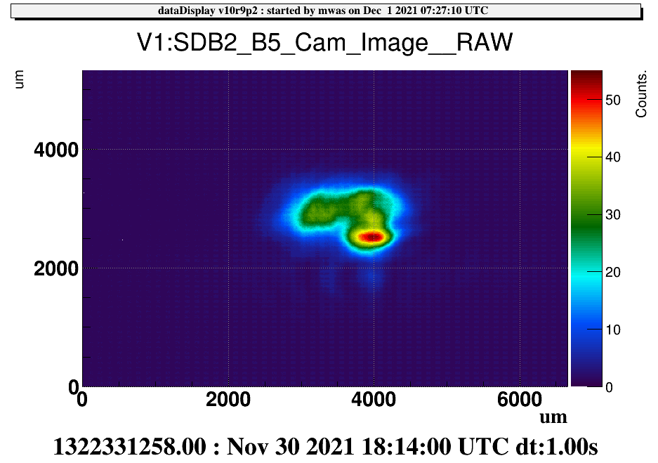
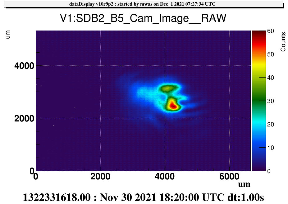
Fig 2, 3, 4, 5 show the B5 camera image as the SR TY position is increased from -244urad to -240 urad. Squiting at these image I see a fixed beam at x~3500um and y~3000um, that has an ellipse shape (width double the height), and on top of that a spot at y~2500um that is moving from left to right from x~3000um to x~4500um. This would indicate that moving SR in TX could be useful to overlap these two spots. As the sideband balance seems the best when the two apparent spots are superposed.
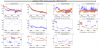
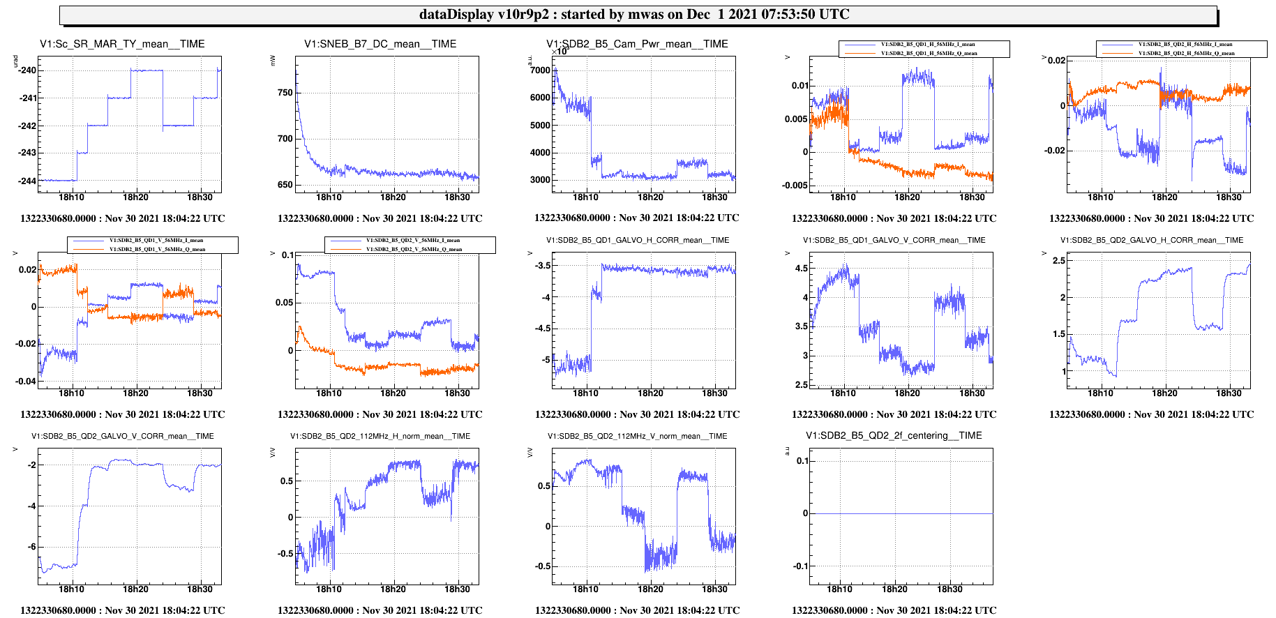
Figure 6 I don't know if SR alignment is controlled using some quadrant error signal. If it is not, B5 QD1 56MHz seems a good candidate, but it is not completely clear. The steps in SR TY are clearly visible, but they are monotonic in the vertical direction on the quadrant. On the horizontal direction the signal goes from a posit offset to zero and the back to a positive offset. B5 QD2 56MHz might work well too, if one assumes that first two steps where out of the linear region of the quadrant, and only SR TY -242, -241, -240urad position where within the roughly linear range. Then the H signal look monotonic, and there is some cross- coupling to the V signal.
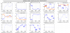
Figure 7 During these steps the B5 quadrants galvo have correction that changed by several Volts, as they try to keep the average beam shape centered. This is done using DC light. It might not be the best choice as the beam has not a Gaussian shape. For B5 QD2 a 2f centering signal (112MHz) is available, and disagrees with the DC error signal on how to center the beam on the quadrant. So trying to use the 2f signal for B5 QD2 could be useful, both types of centering should be tried for controlling the SR alignment. Note that I don't remember if 2f centering loop for B5 QD2 has been tested, or how long ago that test was done.