Reports 1-1 of 1 Clear search Modify search
AdV-ISC (Commissioning up to first full interferometer lock)
derossi, mantovani, pinto, valentini, ruggi, berni - 23:29 Tuesday 30 November 2021 (54055) Print this report
ISC shift: SR alignment and DARM offset tests at CARM null

The goal of the shift was to evaluate the effect of SR alignment with the ITF locked in CARM null configuration. Additionally, other tests have been performed, like the effect of an offset on DARM in the same configuration.

At the beginning of the shift a test together with Romain G. was performed on the drift control of SPRB (see 54054).

After the test was done, we started with the planned activity:

SR (mis)alignment:
For this series of tests we had 5 locks at CARM offset zero: 16.24 UTC, 1734 UTC, 18.04 UTC, 20.40 UTC, and 21.10 UTC, which lasted averagely 30 minutes.

One first different behaviour is the response of the upper and lower SB. Indeed, during the transition to CARM null they didn't exchange immediately, but after a small period of time.
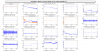
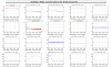
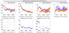
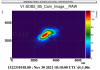
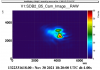
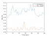
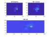
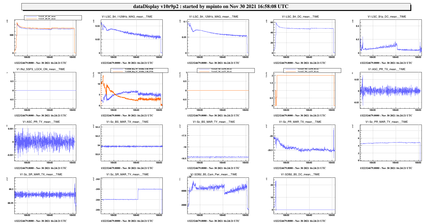
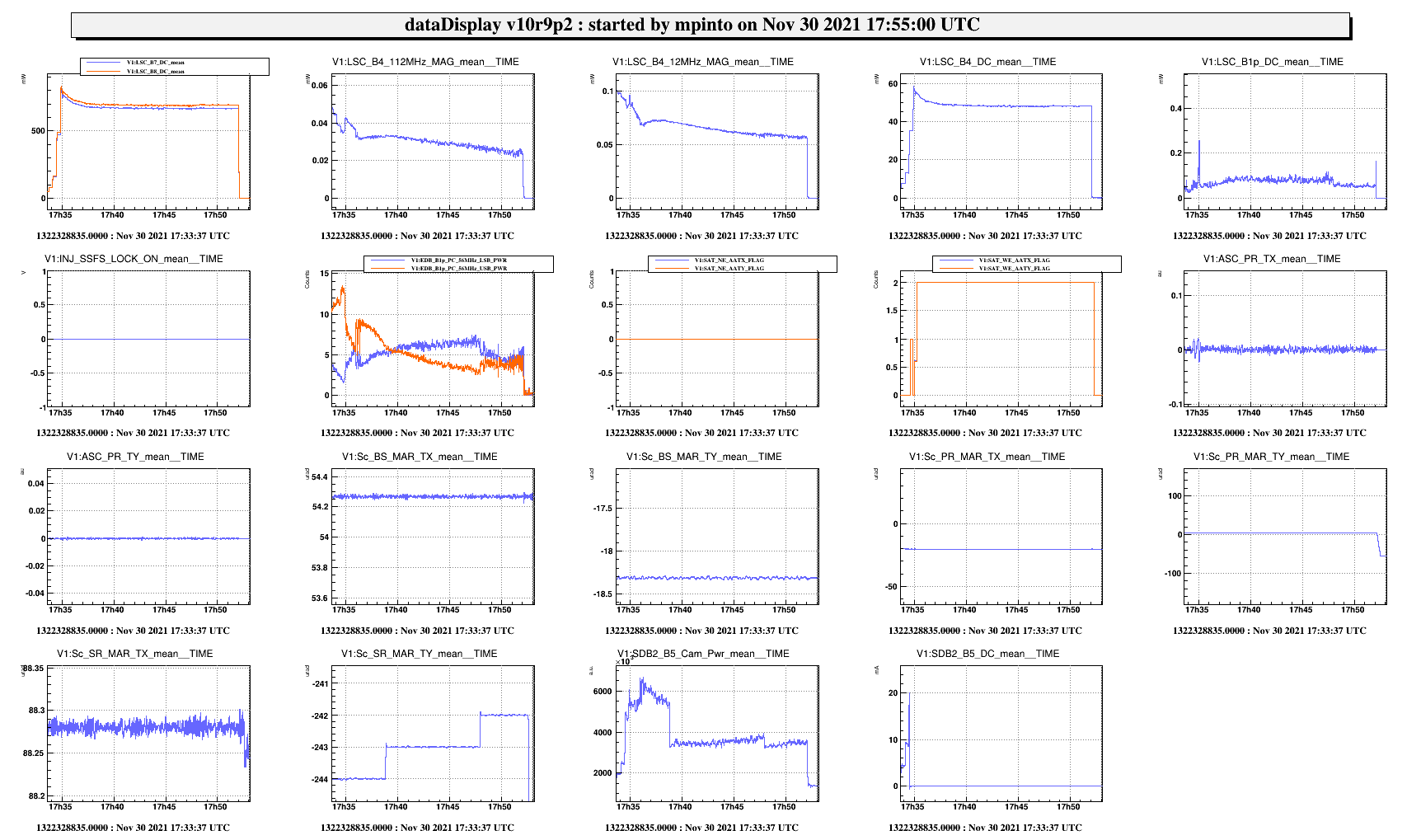
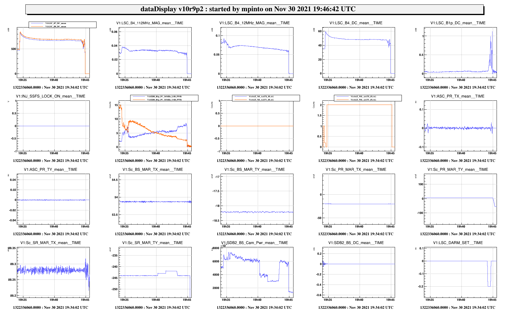
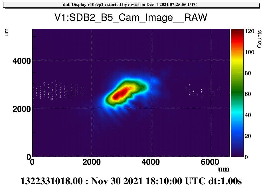
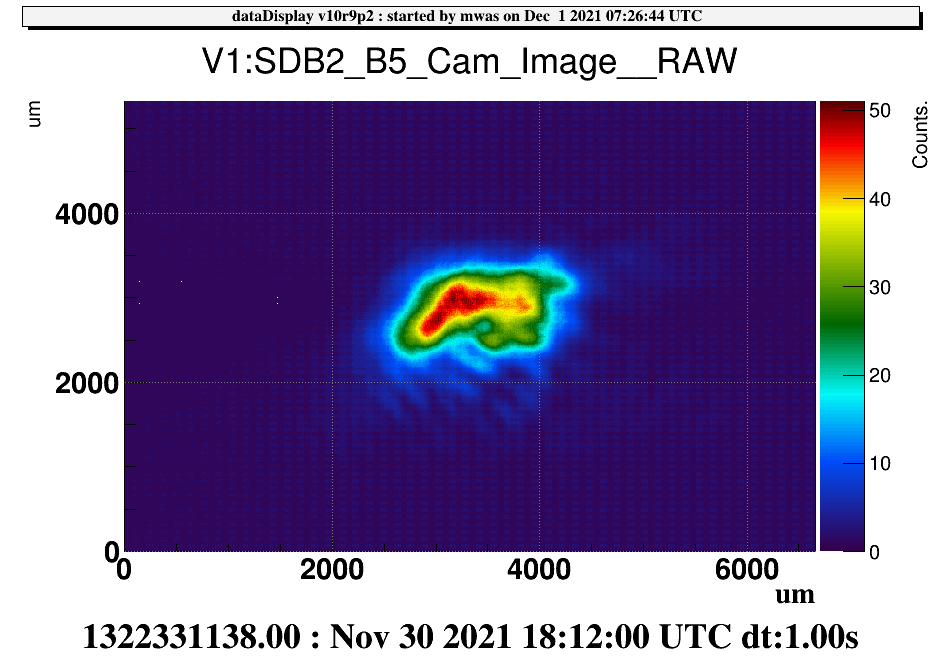
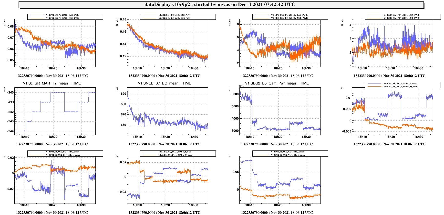
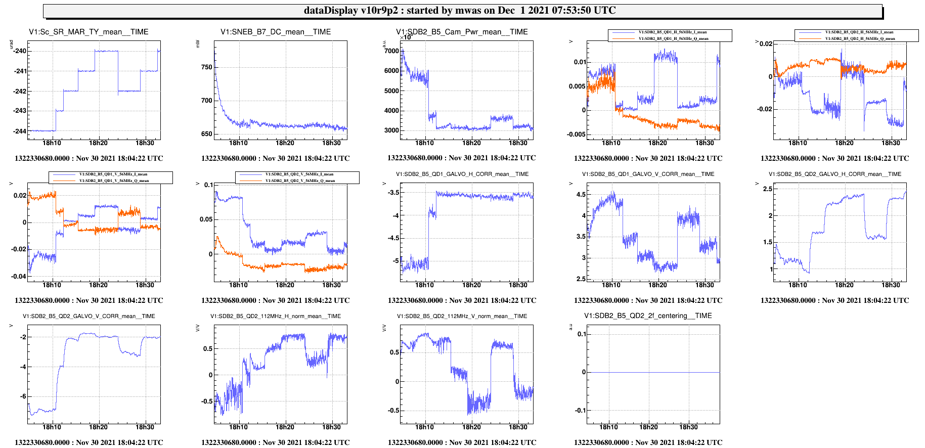
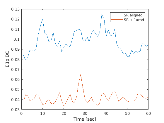
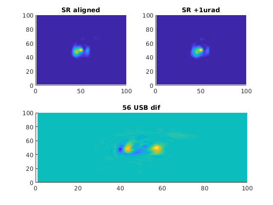
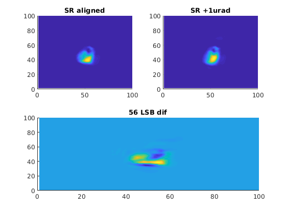
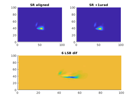
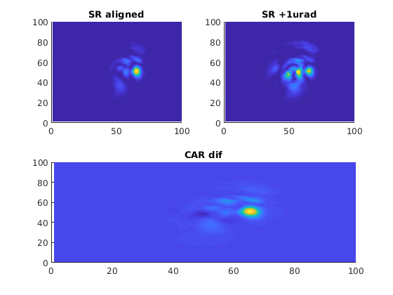
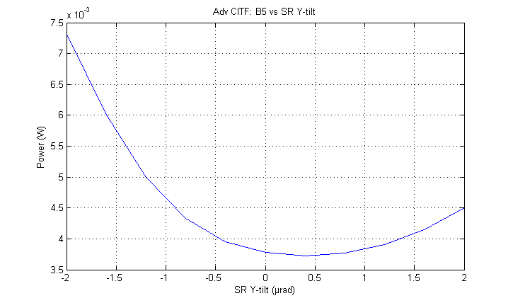
During the first lock we just moved the SR in the positive direction of TY of 1 urad. The effect was immediate: as shown in Fig.1 an increase of the DC powers signals occured, together with a decrease of the value of B1p_DC signal (noticeable as well on the dark fringe cam); the upper and lower sidebands started to balance each other and to behave constantly for the rest of the lock, which lasted around 25 mins.
Following this path, the other locks at CARM null were done increasing the misalignment in order to improve the lock stability (referring to the figures of merit trends).
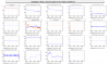
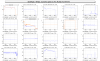
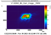
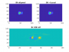
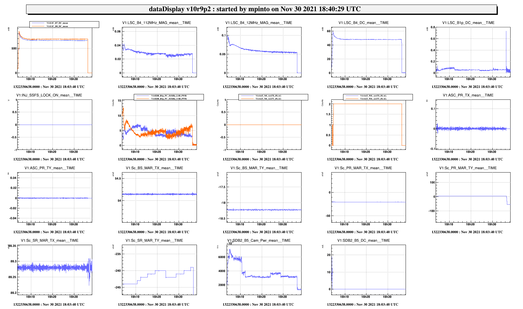
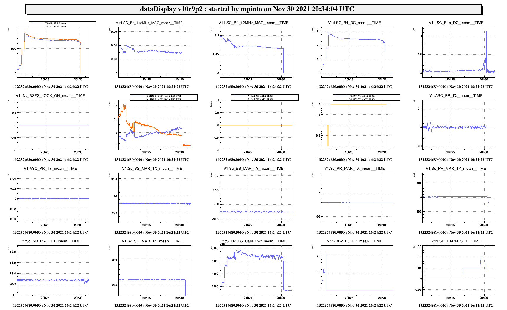
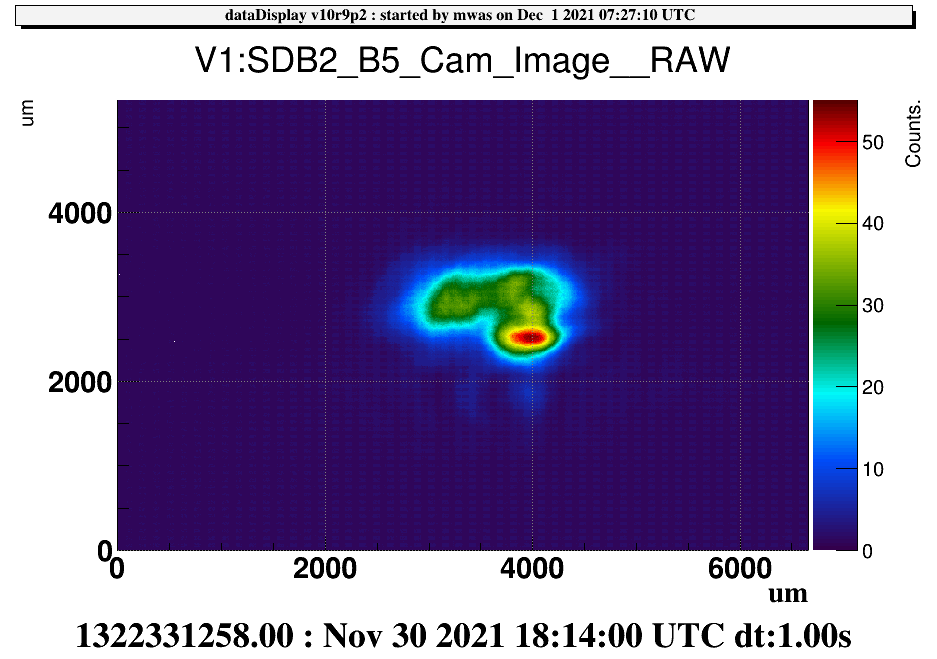
The second lock (Fig.2) behaved the same as the previous with a overall misalignment of 2 urad.
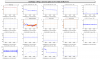
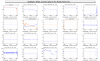
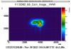
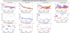
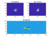
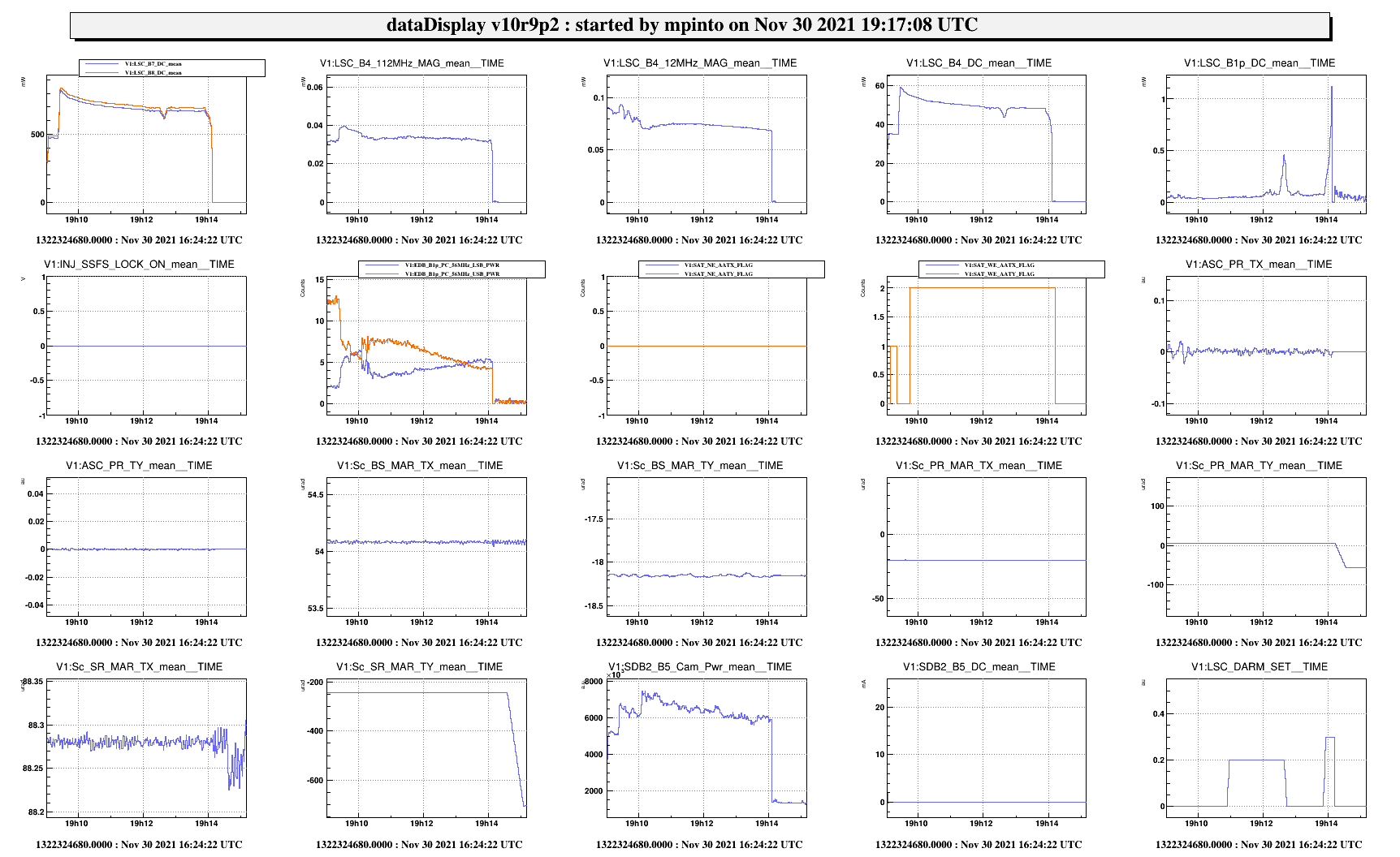
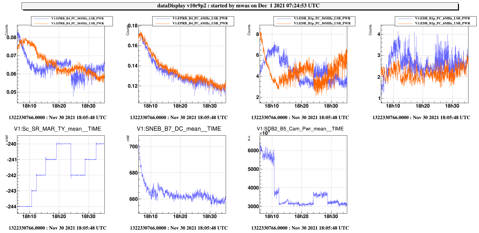
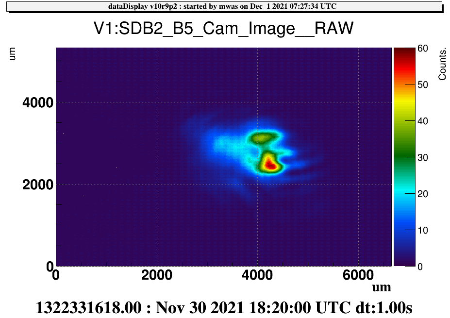
During the third lock (Fig.3) we explored more misalignment positions of the SR in the same direction. What is noticeable from the plot is that:

  • before the swapping of the upper and lower SB, the misalignment of the SR didn't seem to have any effect;
  • after this swap, the effect of the SR misalignment is the one described for the first lock (darkening of the fringe and balancing of the 112 MHz and 12 MHz sb ecc, increase of powers...ecc..);
  • going on with the misalignment (up to 4 urad) the upper and lower SB swapped again, together with a overall improvement of the lock figures of merit;
  • we tried to misalign of 1 more urad (5 overall), but the effect was negative, leading to a brightening of the fringe and general instability with unlock.

During the 4th lock we explored the negative direction of SR misalignment, with an overall misalignment of 4 urad, but we didn't obtain any major improvement as we did with the other direction.

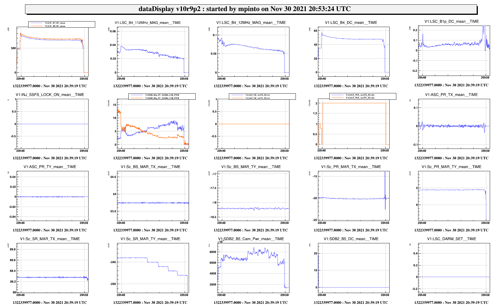
At the 5th lock we tried to go directly to +4 urad of misalignment (the best position explored so far), and tried to complete the full acquisition: we were able to close the SSFS (21.25 UTC). After some minutes we wanted to perform the handoff of MICH and PRCL to the 1f signals but we unlocked.

N.B. For every misalignment step of the SR, corresponds an increase of the DARM UGF, which needs to be manually compensated tuning accordingly the DARM Gain. (We noticed that even if the optimal UGF for DARM is 45 Hz, today the loop behaved more stably with a lower UGF, around 38 Hz).

DARM offset:
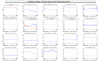
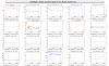
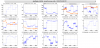
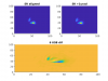
In order to evaluate the effect of DARM offset on the stability of the lock, we performed some tests, in which we applied some offset in both negative and positive directions (see Fig.s from 6 to 8). The expected effect was a general worsening of the fringe together with the increase of such offset. Every offset, even if little and with a slow enough ramp, led the ITF to unlock due to heavy brightening of the fringe.

A better analysis of the data of this shift will be further performed. More tests will be performed in the following shifts as well.

We left the ITF with the arms locked on the IR.

Images attached to this report
Comments to this report:
mwas - 8:58 Wednesday 01 December 2021 (54061) Print this report

In addition to these very interesting finding one can notice a few more things

Fig 1. The SR alignment has an impact on the balancing of the 56MHz sideband (as seeon the B4 and B1p phase camera), but no visible impact on the 6MHz sideband. This is expected as the 6MHz sideband should not enter the SR cavity. The power on the B5 camera is reduced at the same time as the steps in SR TY alignment are done.

Fig 2, 3, 4, 5 show the B5 camera image as the SR TY position is increased from -244urad to -240 urad. Squiting at these image I see a fixed beam at x~3500um and y~3000um, that has an ellipse shape (width double the height), and on top of that a spot at y~2500um that is moving from left to right from x~3000um to x~4500um. This would indicate that moving SR in TX could be useful to overlap these two spots. As the sideband balance seems the best when the two apparent spots are superposed.

Figure 6 I don't know if SR alignment is controlled using some quadrant error signal. If it is not, B5 QD1 56MHz seems a good candidate, but it is not completely clear. The steps in SR TY are clearly visible, but they are monotonic in the vertical direction on the quadrant. On the horizontal direction the signal goes from a posit offset to zero and the back to a positive offset. B5 QD2 56MHz might work well too, if one assumes that first two steps where out of the linear region of the quadrant, and only SR TY -242, -241, -240urad position where within the roughly linear range. Then the H signal look monotonic, and there is some cross- coupling to the V signal.

Figure 7 During these steps the B5 quadrants galvo have correction that changed by several Volts, as they try to keep the average beam shape centered. This is done using DC light. It might not be the best choice as the beam has not a Gaussian shape. For B5 QD2 a 2f centering signal (112MHz) is available, and disagrees with the DC error signal on how to center the beam on the quadrant. So trying to use the 2f signal for B5 QD2 could be useful, both types of centering should be tried for controlling the SR alignment. Note that I don't remember if  2f centering loop for B5 QD2 has been tested, or how long ago that test was done.

Images attached to this comment
mantovani - 12:02 Wednesday 01 December 2021 (54063) Print this report

From the lock of yesterday two things interesting things can be highligthed.

The first one is the different behavior of the 56MHz sideband that changed completely after the change of SPRB control (from the DC of B4 QD2 to the 112MHz control)

As it is visible the 56MHz sidebands are not anymore swapped at carm null and they start from a more balanced condition, see Figure 1. To be verified that the only origin of the change is the SPRB control.

The second interesting effect is the misalignment of the SR (+1urad), which has strongly improved the B1p DC (lower value and no raising trend).

If we compare the sideband and carrier images in the B1p phase camera (SR aligned on the left and misaligned on the rigth) there is an improvement on the balancing but may be also a reduction of an 01 mode in the horizontal direction of the 56MHz sideband (bottom plot is aligned - misaligned). Moreover the carrier becomes more symmetric.

To be understood

It is intersting also to understand why the SR  can be misaligned in the plus direction (+TY) up to 5 urad while if we misalign in the minus direction (-TY) we loose immidiately the lock (spurious beams on the SDB1?)

For this reasons we decided togheter with DET to perform two more steps:

- align the SPRB on the 12MHz instead of the 112MHz (to see the effect on B4 6MHz used for CARM) while we are at Carm 0

- repeat the test of the SR misalignment while the SDB1 bench control on B5 QPD is engaged


Images attached to this comment
pichot - 11:32 Thursday 09 December 2021 (54163) Print this report
In addition, I simulated with DarkF, the CITF with the BS wedge and AR surface to obtain the B5 beam. Then I add some angular tilt (in X and Y axis) on the SR mirror, to see the B5 power variation and shape, for -2µrad to +2µrad.
Images attached to this comment
Search Help
×

Warning

×