Reports 1-1 of 1 Clear search Modify search
AdV-PSL (Laser Bench setup)
derossi, spinicelli, chiummo, melo - 22:21 Tuesday 11 May 2021 (51750) Print this report
swap ML

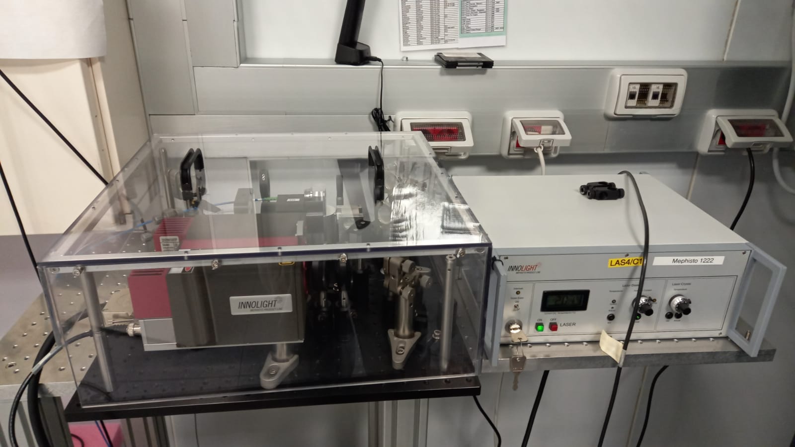
The goal of the activity was to swap the ML with the spare previously brought in the laser lab atrium 51579.

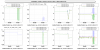
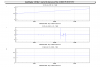
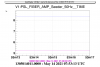
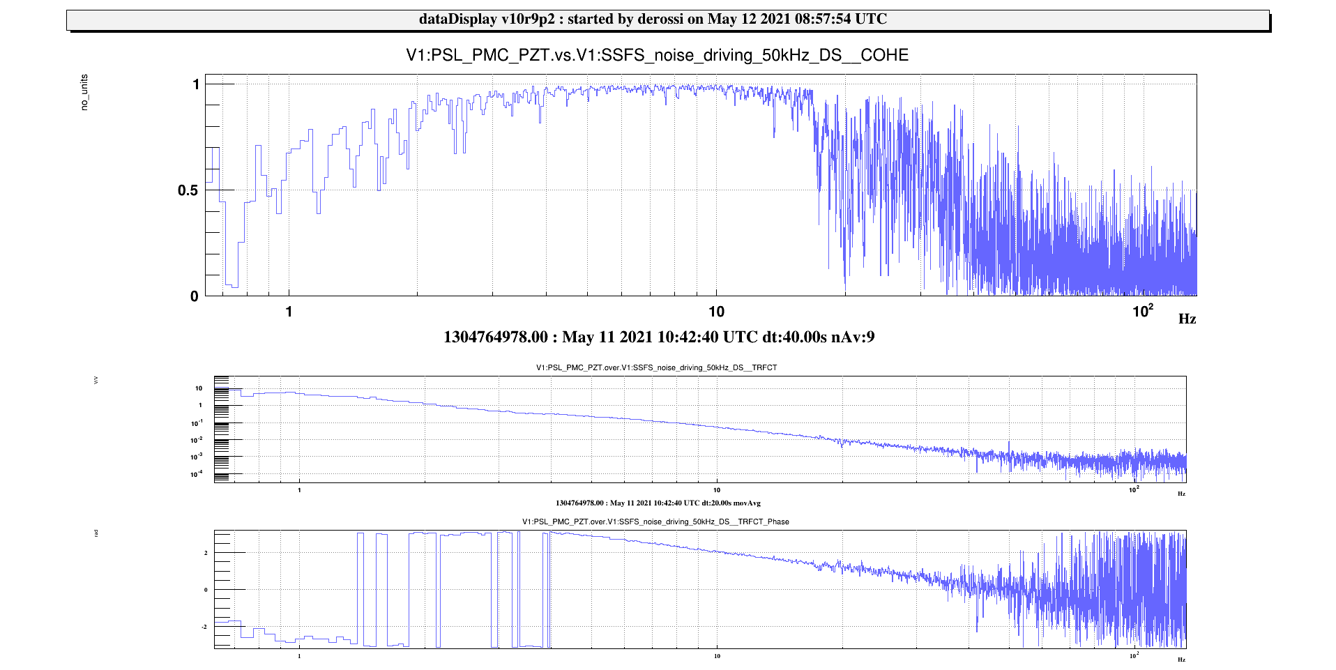
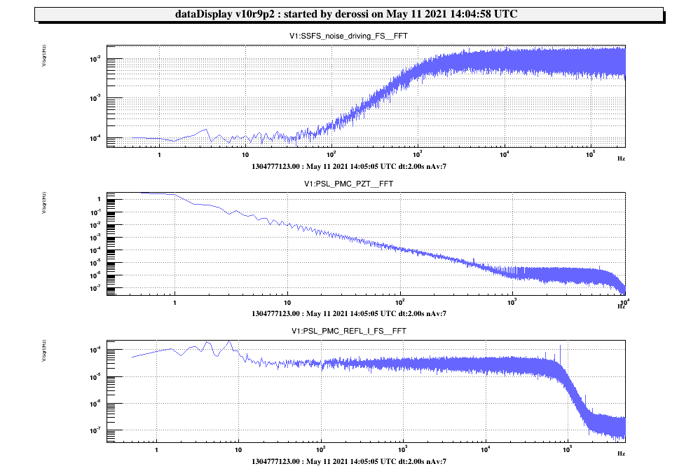
We starting by measuring the TF of the PZT and thermal loops on the installed ML. We then switched off the fiber amplifier and measured the power at the output of the ML fiber (470 mW) and of the pickoff for the amplifier (132 mW).

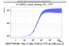
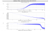
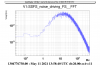
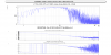
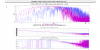
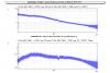
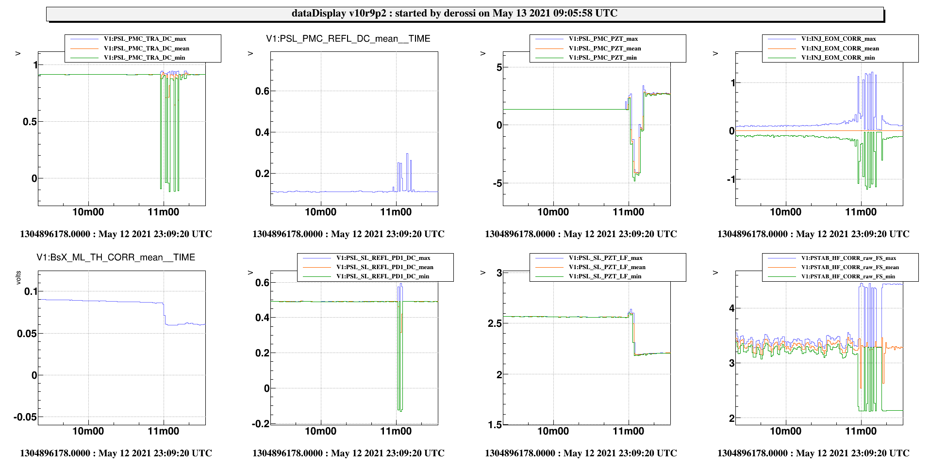
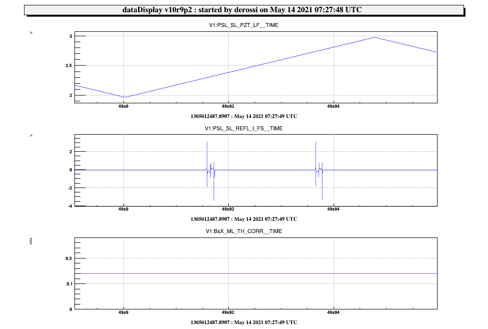
We turned on the ML spare and checked the coupling on the fiber but we did not find the expected 83%. We obtained at the best 50%. We connected this fiber to the one going to the LB (410 mW at the output of the fiber, 940 mW output ML) and we switched on the fiber amplifier and we had to wait a bit for the amplifier to stabilize and when we locked the PMC we found out a quite large misalignment, so that we had 0.6 V od transmission when locked instead of 0.91 V. We measured the new PZT and thermal transfer functions and found they had a similar behaviour (to be confirmed by deeper analysis).

Because of the poor PMC transmission we decided to swap again to the old master laser. However, when plugging again the fiber there was no light at the output, probably due to a misalignment of the collimator. We struggled to inject again light into the fiber and we never recovered the 470 mW. We measured in fact 160 mW at max. 

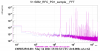
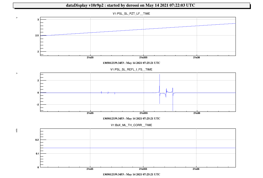
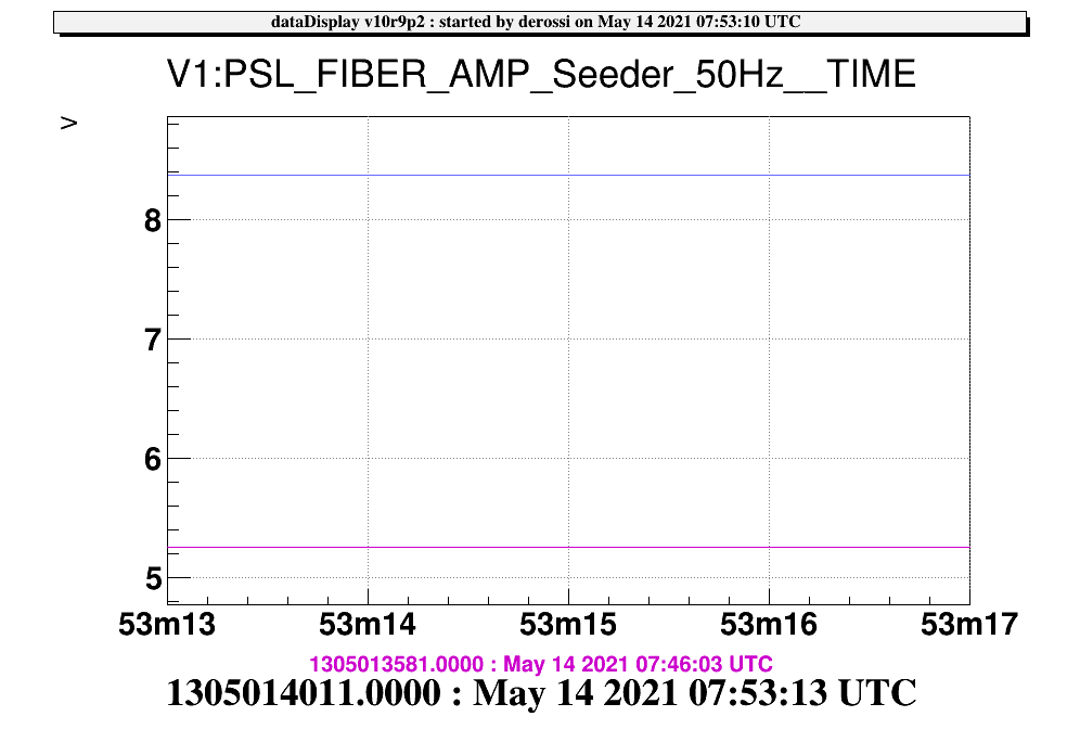
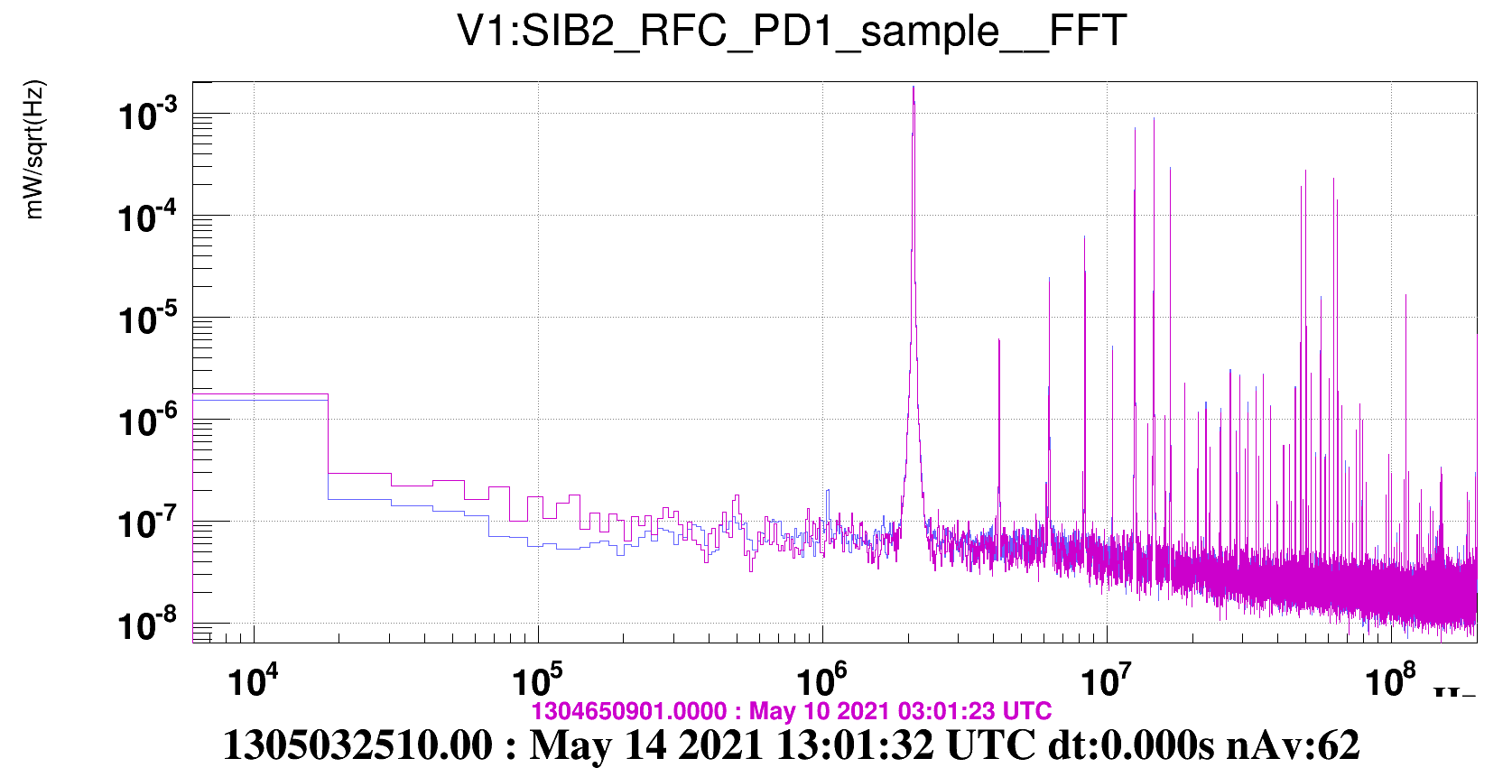
Given this issue we decided to use the spare ML. Nevertheless we didn't manage to find again the same coupling. We realized that a fiber (the 15 m long with metallic jacket) was burnt. We then installed the fiber that had been used for ALS and was fixed below the floating floor. We obtained around 200 mW at the output of the fiber on the LB with 2A driving current. We then turned on the fiber amplifier and we relocked everything. We checked that we have no peak due to the noise eater when leaving the lab and that the green sources had correctly switched on again.

More details will be given tomorrow.

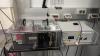
We should add a box to protect the new ML from air flux, which has been made today from the mechanicians (thanks). 


Comments to this report:
derossi, melo, spinicelli, chiummo - 17:00 Thursday 13 May 2021 (51758) Print this report

The so called ML spare, which has been swapped and is now running is the Mephisto 1000NE SN: 1222

The procedure we followed (previously discussed with M. Turconi and W. Chaibi) is reported below:

  • IMC unlocked
  • ML thermal and PZT corrections disconnected. The ML current is 2A and the crystal temperature 22.75 C
  • Measurement of the ML PZT loop TF. The purpose was to measure the TF of the ML piezo to an excitation and compare is with the spare ML, in order to verify that the two responses are similar. First of all we checked the control bandwidth of the PMC piezo loop by injecting sinusoidal lines of 1.6Vpp amplitude directly on the PZT input of the ML and looked on the Pre mode cleaner piezo corrections PSL_PMC_PZT and found a cutoff frequency of 1400 Hz (1st plot).
GPS (Local Time) Freq [Hz] Amplitude [Vpp] Comments
09:57:20 102 1.66 V  
09:59:20 211 -  
10:01:00 501 - -
10:04:30 901 - -
10:10:50 1990 - the piezo doesn't follow, out of the band
10:13:50 1320 -  
  • We injected noise on the ML PZT with the fast DAC. The filter used for the noise is the one in Acl called SSFS noise IMC which has a zero at 100 Hz and a pole at 1000 Hz (2nd plot). However we didn't manage to exploit data since we found out we had no coherence between the PSL_PMC_REFL_I and the noise (plot 3). Next time we should increase the amplitude of the applied noise if we want to measure the TF in this way.
  • Measurement of the ML TH loop TF. We injected noise with a fast DAC. The filter has a zero at 1Hz, a pole at 5 Hz at another pole at 40 Hz (4th plot), and measured the TF (5th plot).
  • We switched off the fiber amplifier and measured the power in transmission of the ML fiber on the LB and of the pickoff for the fiber amplifier seeder (470 mW and 132 mW)
  • We injected the spare ML into the fiber going the LB. We set it at 2.074 A and the crystal temperature at 24.73 C. However, we didn't recover the same coupling 51579. However, since the fiber amplifier works in saturation, it was enough to switch it on again and also lock the SL.
  • Measurement of the ML PZT loop TF, with the same filter of fig. 2 (plot 6).
  • Measurement of the spare ML TH loop. We found a similar response (plot 7, in blue is the spare ML, in pink the previous measurement).
  • While doing this operation we misaligned the collimator of the ML previously installed. We struggled to reinject it and we didn't manage to recover the same output power. We have now around 130 mW in transmission of the fiber and we should optimize this coupling soon.
  • We measured the IMC TF function and adjusted the gain. We passed from 4 to 6 dB attenuation and recovered a UGF of 140 kHz (plot 8).

We let the system locked with the spare ML and until now we did't observe any strange behaviour of the noise eater (as it was the case for the old ML).

However, we should check and maybe tune the crystal temperature because we are probably next to a mode hop. The instability observed yesterday (51771) is probably due to a bimodal behaviour of the ML (9th plot).


Images attached to this comment
derossi, spinicelli, chiummo We - 11:56 Friday 14 May 2021 (51786) Print this report

**** tuning of the ML crystal temperature ****

In order to correct the bimodal behaviour of the ML (1st plot. We were at 24.76 C and at 25.55 C we started to observe the second mode) we tuned the temperature of the ML crystal. Following the procedure (50944) we found mode hopes appearing between 20.88C- 21.4 C,  24.1 C - 24.55 C and 27.3 C- 27.85 C.

We lowered the temperature from 24.76 C to 23 C (2nd plot).


**** increasing of the fiber amplfier seeder power ****

Following Walid's advice we increased the seeder power from 40 mW to 70 mW, which corresponds to 8V on the photodiode (3rd plot), in order to have more margin for seeding and avoid switch off if any polarization  fluctuations or small misalignment occur.

We switched off the fiber amplifier and turned the waveplate before teh pickoff cube from 70 deg to 77 deg. The SL still locks.

We also measured the power at the output of the ML fiber and we have 175 mW.

After having turned on again the fiber amplifier we relocked the injection.

Once all the loops closed an unlock of the PMC occurred but we didn't identify its cause. It relocked by itself few minutes later and until now it seems to be stable. We keep monitoring the SL behaviour because it could be that we ara close to the threshold for unlocking and whenever it unlocks some light could perturb the fiber amplifier or the ML. It this case a solution will be to keep the SL unlocked and put a beam dump at its output.

Images attached to this comment
chiummo, derossi, melo, spinicelli - 14:54 Friday 14 May 2021 (51787) Print this report

On wed 12/5, around 12:00 LT, we also took some time to install a provisional plexiglass box on the spare ML breadboard in order to decrease the impact on the setup of environmental variations and air flux.

Images attached to this comment
chiummo, derossi, melo, spinicelli - 16:52 Friday 14 May 2021 (51792) Print this report

To be noted: as mentioned in the previous comments, the internal noise eater loop of the new installed ML seems to work properly (plot 1, in purple old-installed ML during a period of correctly working noise eater). Untill now, despite multiple intervention in laser lab, we weren't able to trigger the ~680 kHz oscillations as it was possible with the previous master (plot 2, in purple old master during 680kHz oscillation).

The behaviour of the installed master laser will be studied during next weeks as well as its possible influence on fast unlock. 

Images attached to this comment
Search Help
×

Warning

×