The aim of the shift was to study the relative gain between the 1f and 3f error signals used for the CITF lock and to tune the quadrants for the CITF alignment.
After the tuning of the B2 PDs and QDs' VGA gains perfomed by Gouaty and Masserot (see entry 51154) the DRMI CITF was locked at 16.00 UTC.
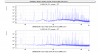
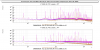
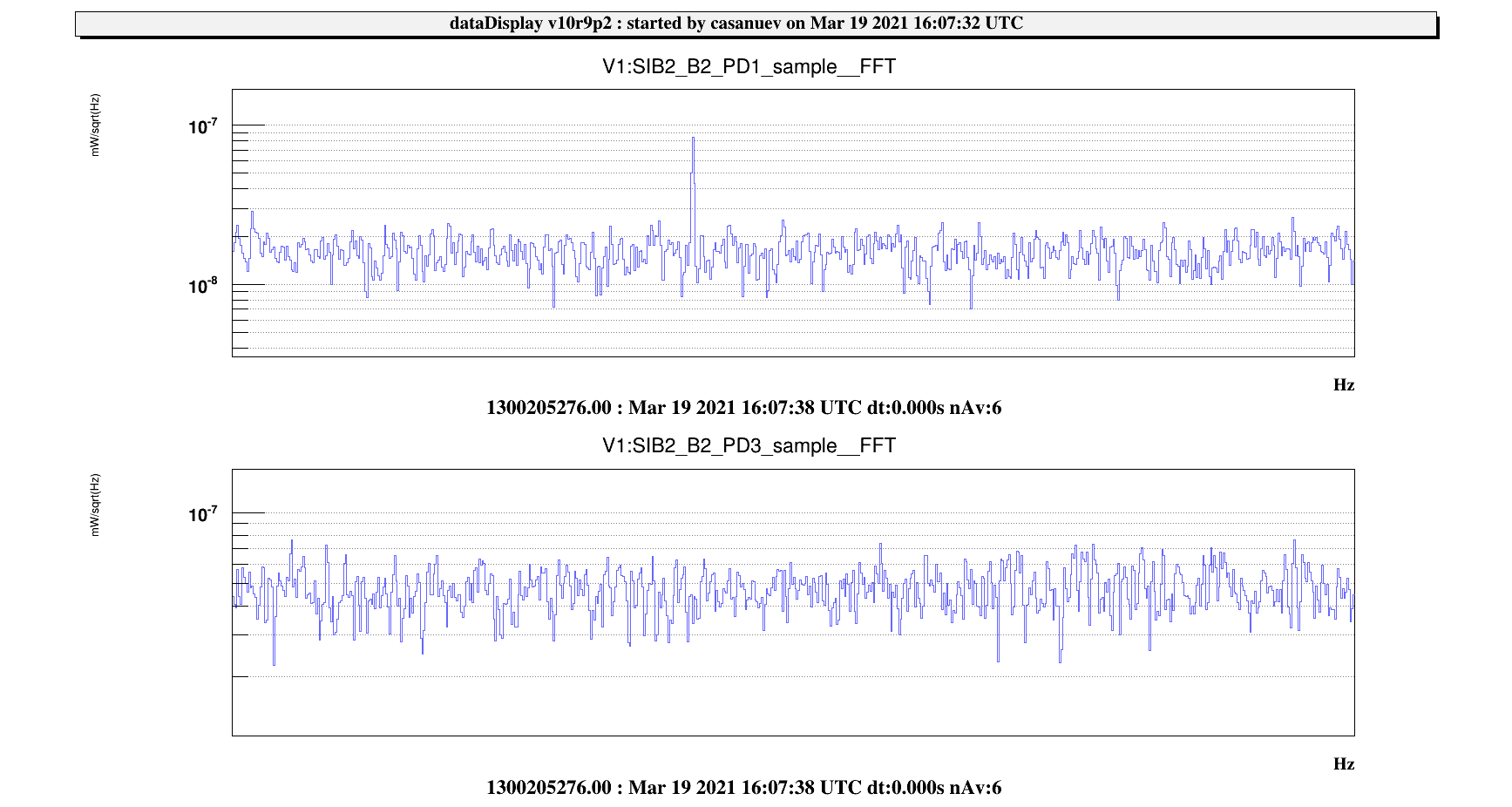
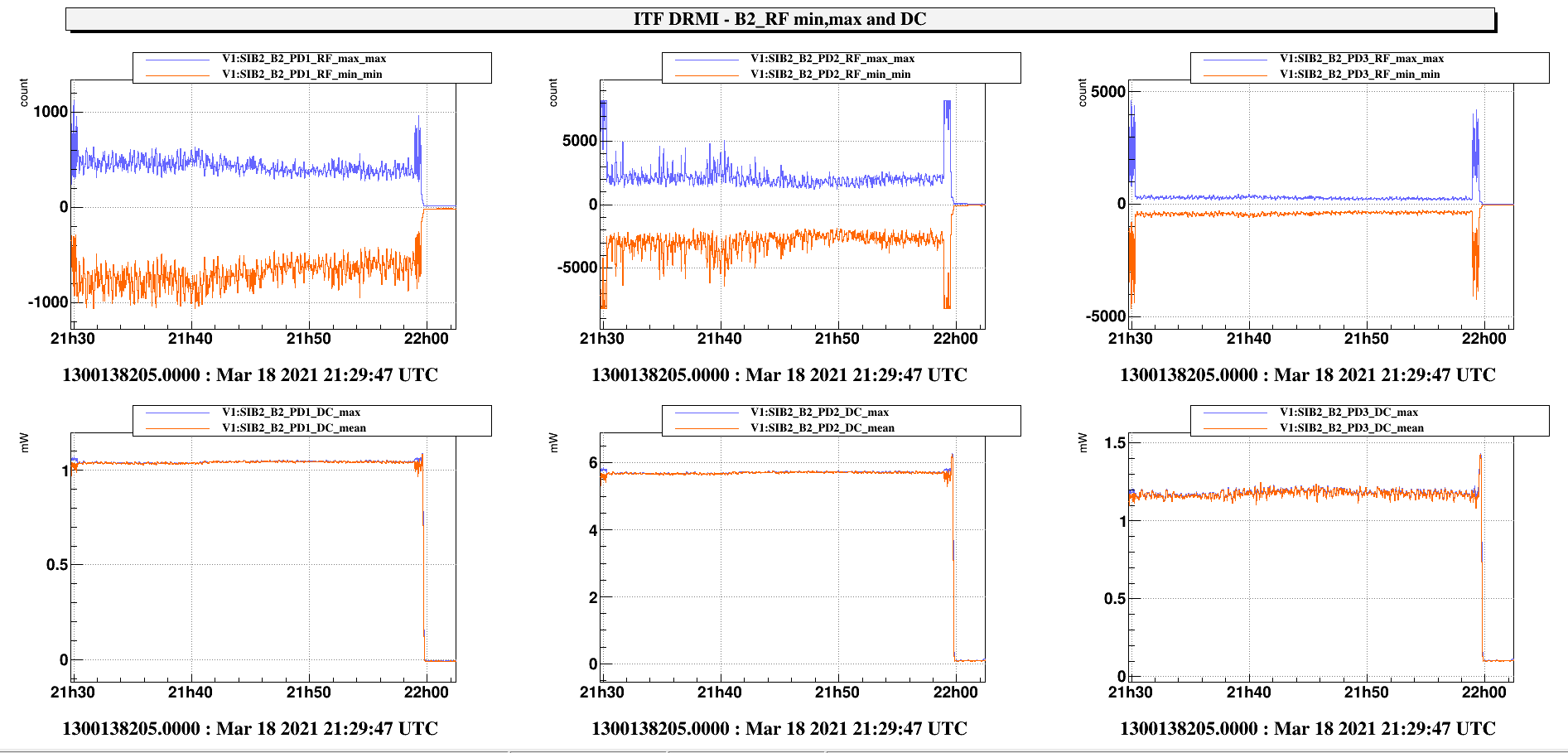
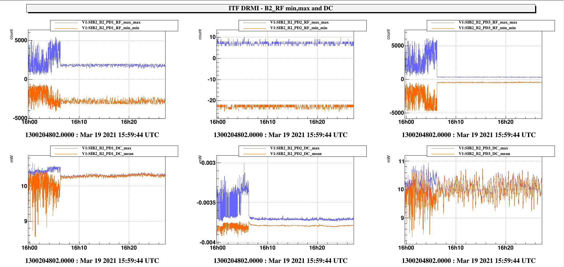
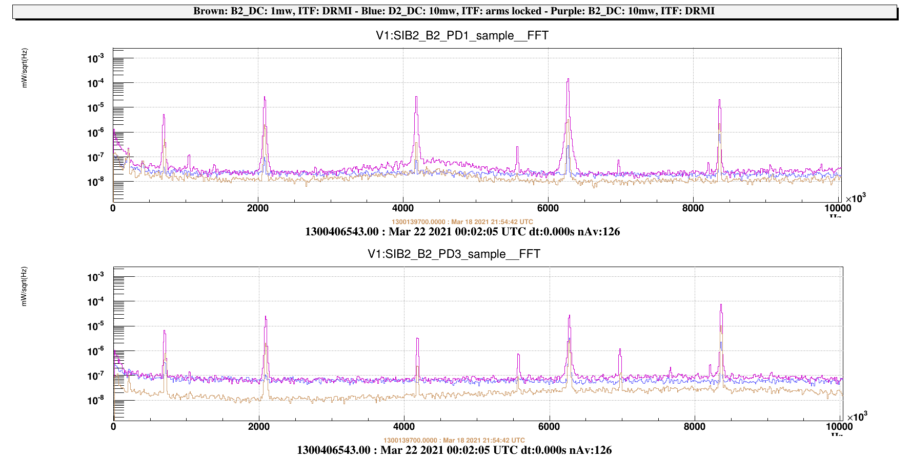
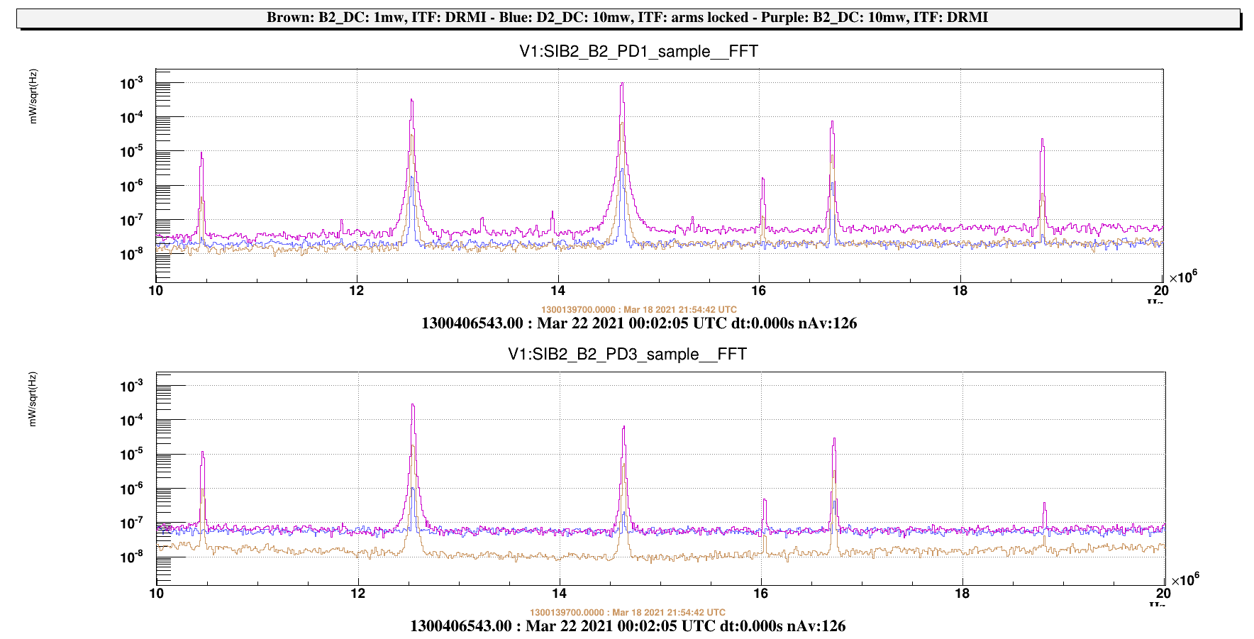
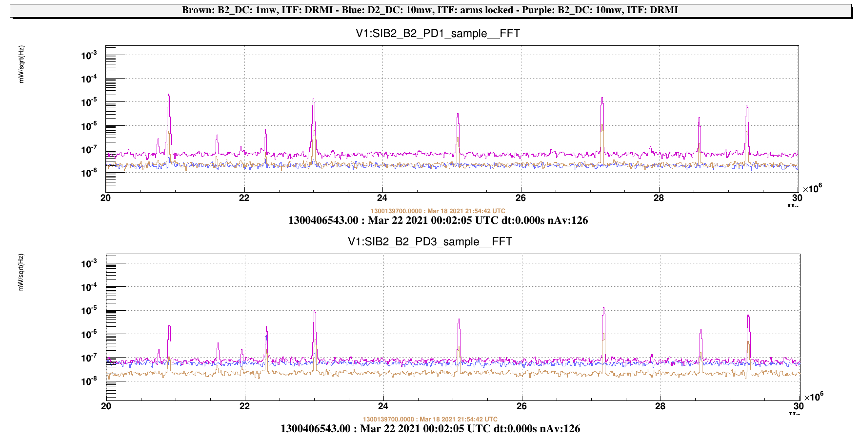
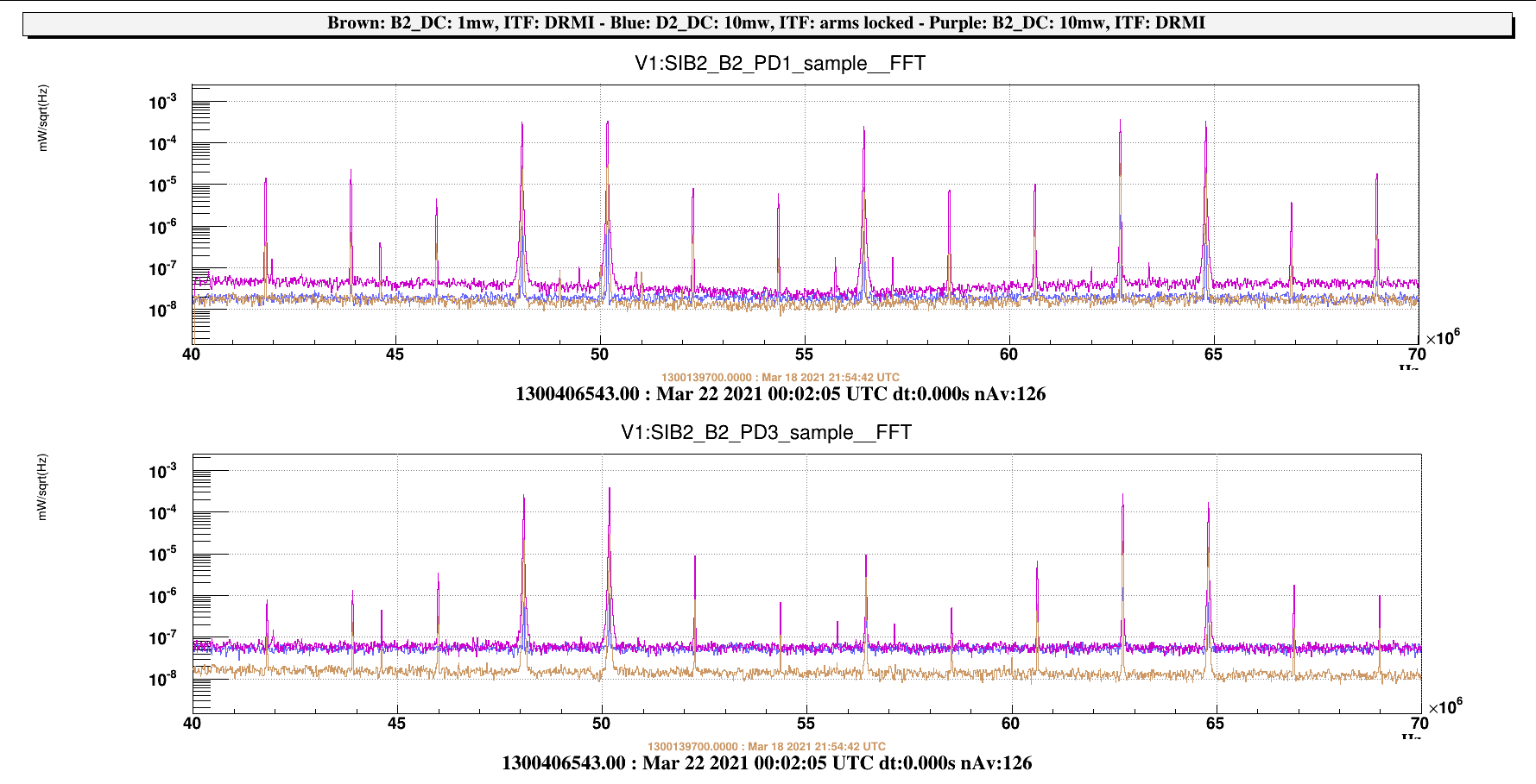
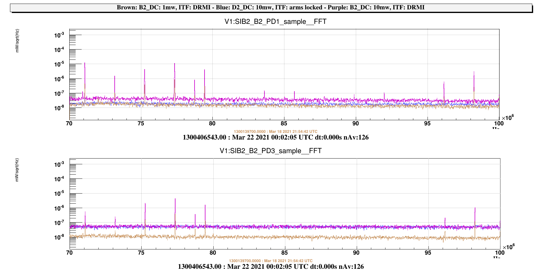
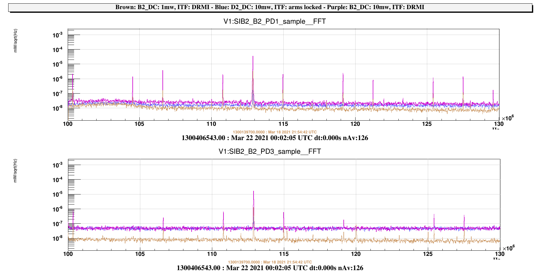
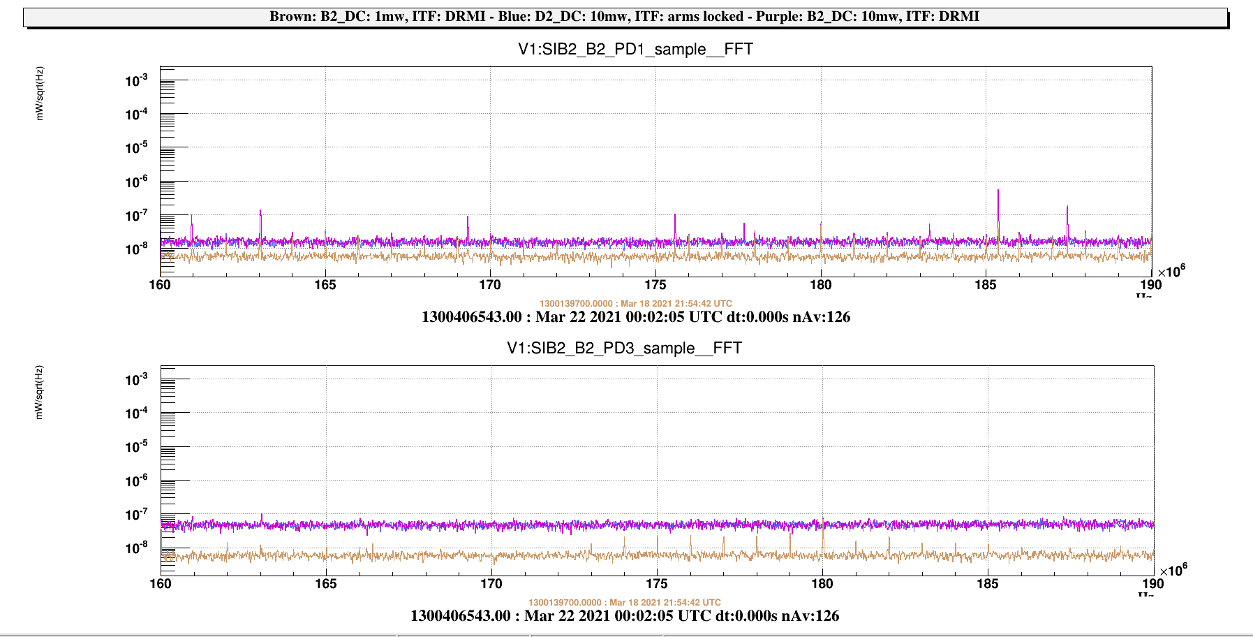
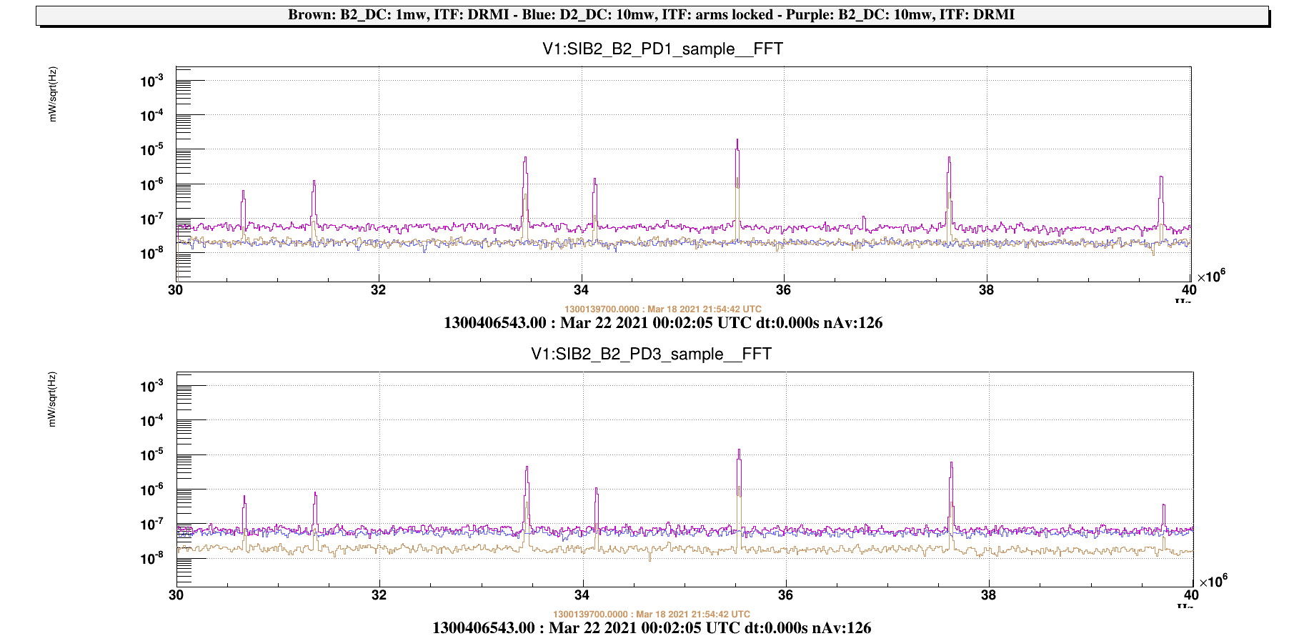
Figure 6 shows that the B2_PD1 photodiode is affected by numerous noise lines, suggesting a possible start of saturation of the preamplifier. Figure 7 Shows the the B2_169 MHz signal amplitude when the CITF is locked, Figure 8 shows that the B2_PD1 and B2_PD3 signals did not saturate the ADC during the shift.
The first activity focused then on injecting lines on the citf LSC loops above the UGF frequency to check of the 1f and 3f signals, as follows:
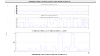
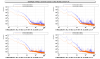
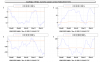
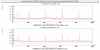
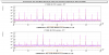
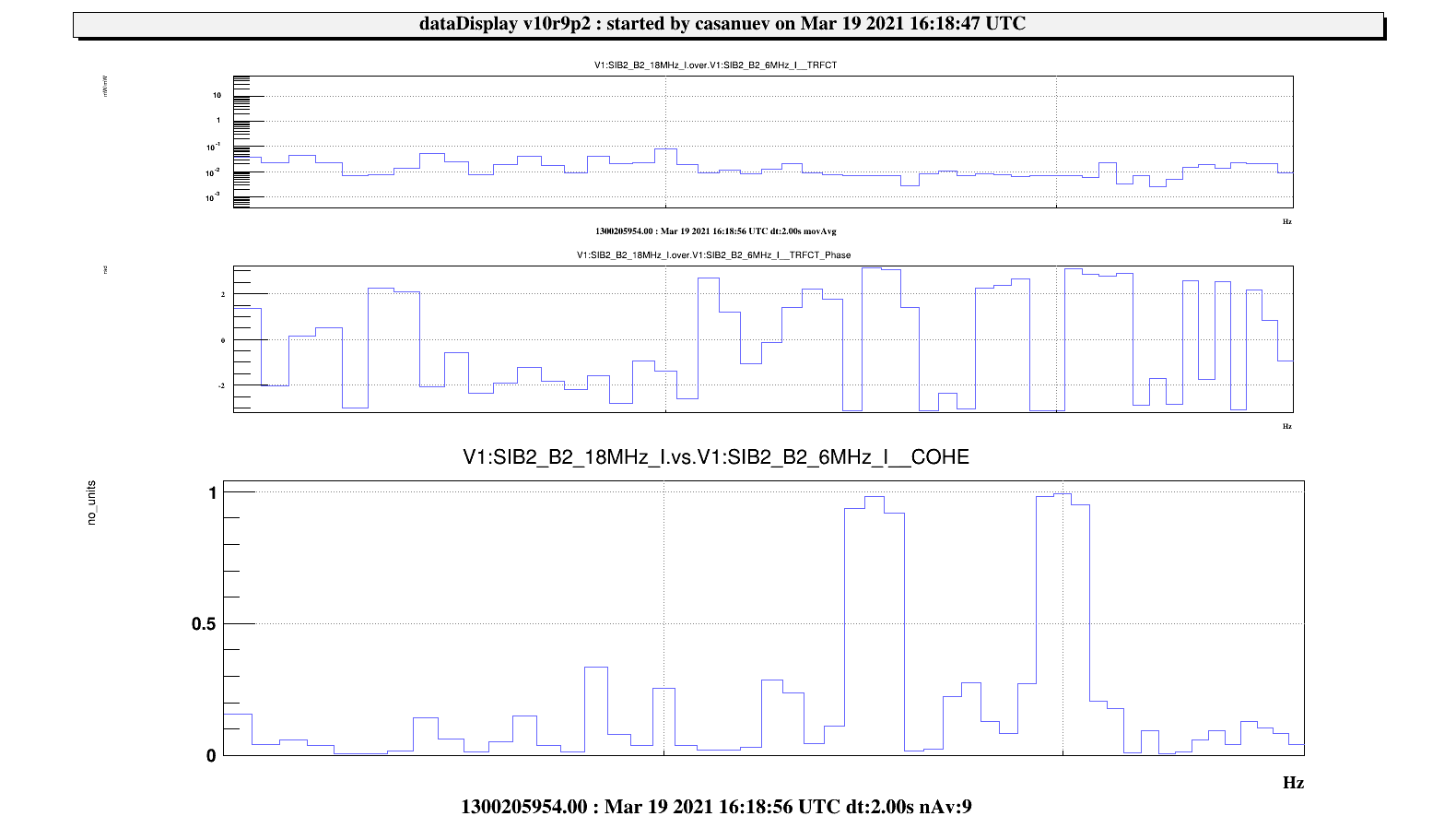
- 16.16 UTC: PRCL injection. Freq: 45 Hz, amplitude 5e-4. The measured ratio between the B2_6MHz_I and B2_18MHz_I error signals resulted 7e-3 (See figure 1).
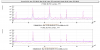
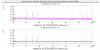
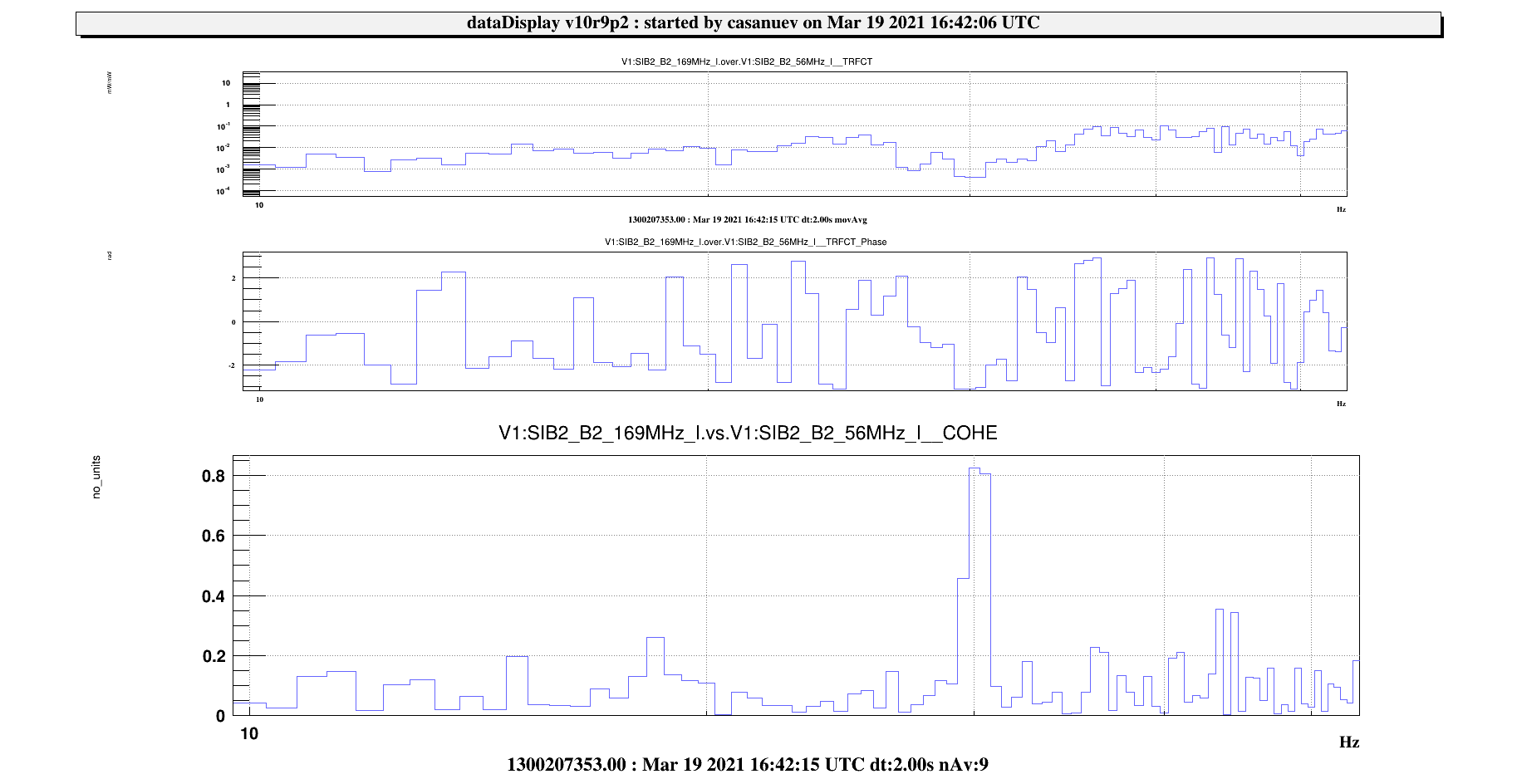
- 16.35 UTC: MICH injection. Freq: 30 Hz, amplitude 5e-1. The demodulation phase of the 3f signal B2_169MHz required tuning, the new phase is 1.3 rad. The ratio betwen the B2_169MHz_I and B2_56MHz_I signals resulted in -4e-4.(See figure 3)
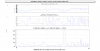
During the MICH injection, a strong coupling between the B2_56_MHz_I and B2_56_MHz_Q (used respectively for the MICH and SRCL lock) signals has been noted ( see figure 2). Therefore, the B2_56MHz PD phase was retuned (while injecting a line on SRCL). The phase of the B2_56_MHz_I photodiode has been changed to 1.15 rad. Some attempts to change the MICH driving matrix in order to furthermore reduce the MICH-SRCL coupling (while injecting a line on MICH) has been attempted without obtaining substantial improvement. The MICH-SRCL coupling is very high, this needs to be better understood.
At 17.20 UTC the PR alignment was also retuned to increase the lock stability.
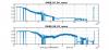
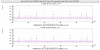
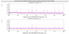
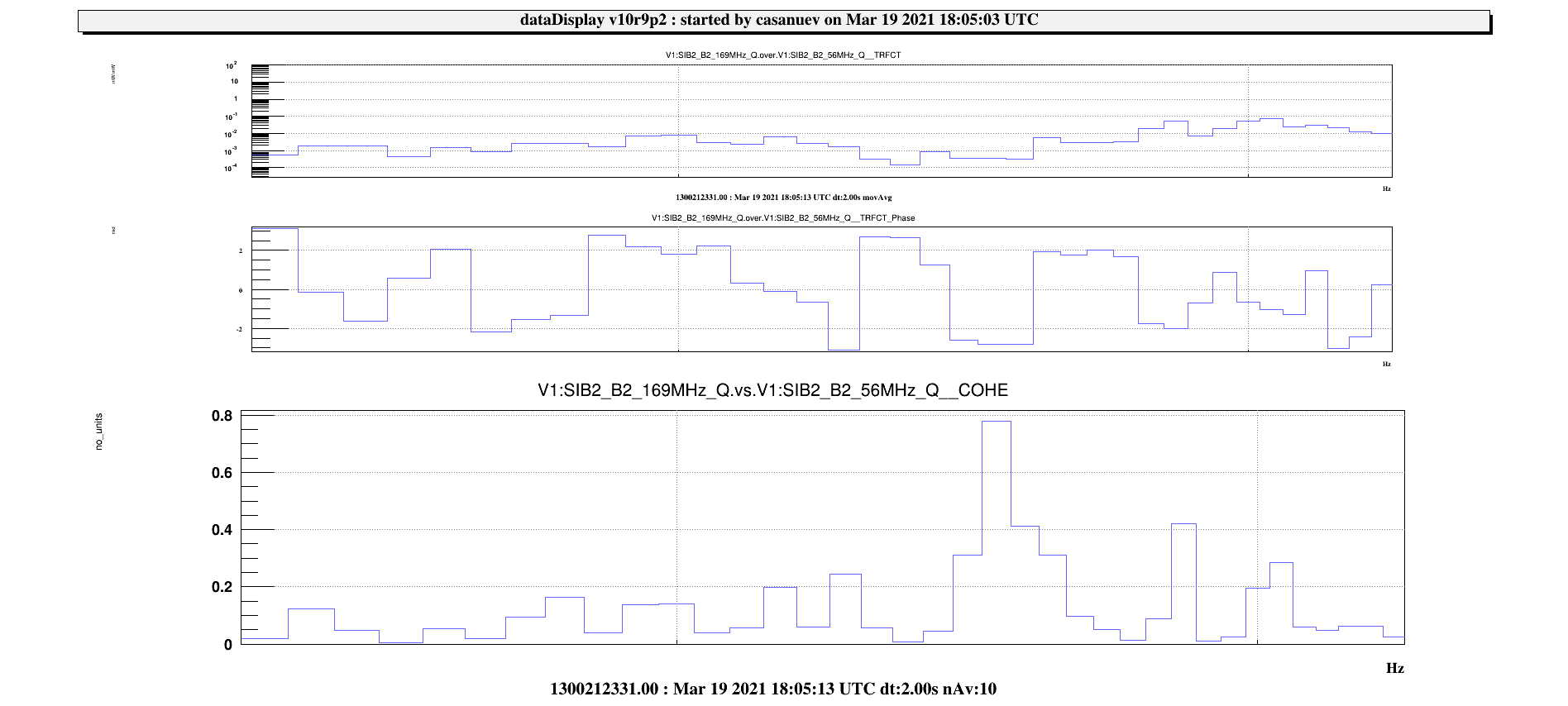
- 18.05 UTC: SRCL injection. Freq: 25 Hz, amplitude 2e-1. The ratio betwen the B2_169MHz_Q and B2_56MHz_Q signals resulted in -3.6e-4 (see figure 4).
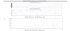
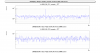
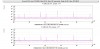
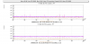
At this point an unexpected oscillation at 11 and 38 Hz affecting all the CITF error signals (see figure 5) brought the loops close to saturation, requiring us to disengage the CITF lock at 18.13 UTC.
The CITF was relocked at 18.34 UTC. in order to proceed with the second activity, focused on studying the B2_6MHz QPDs. The study of the B4 QPDs was instead not possible due the impossibility of engaging their corresponding galvo loops.
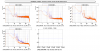
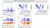
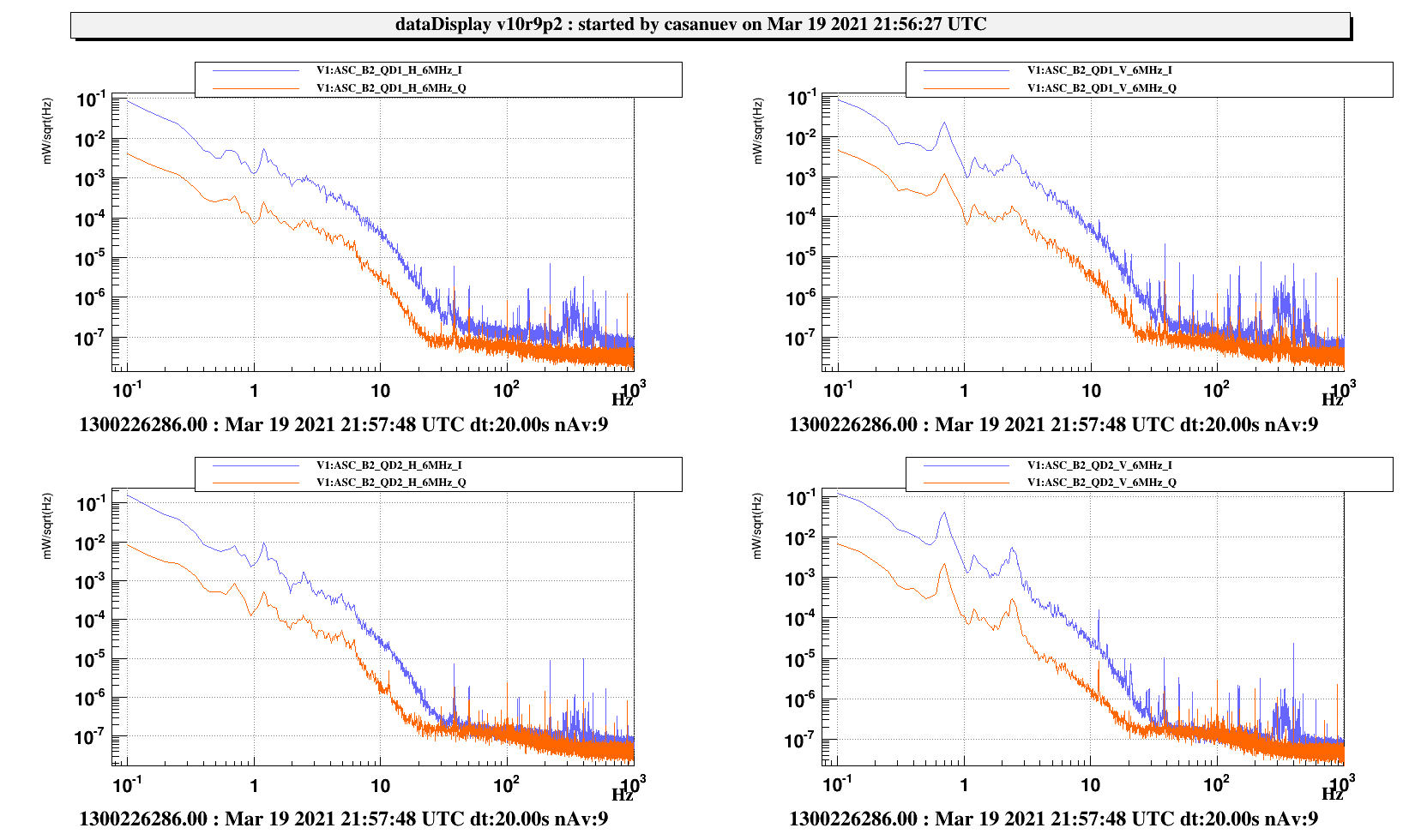
Figure 9 shows that the B2_6MHz QPDs are affected by an unexpected noise below 20 Hz.
Since the CITF lock was very unstable at this point, a complete realignment of PR and SR mirrors was performed and the CITF was relockeda gain at 20.40 UTC.
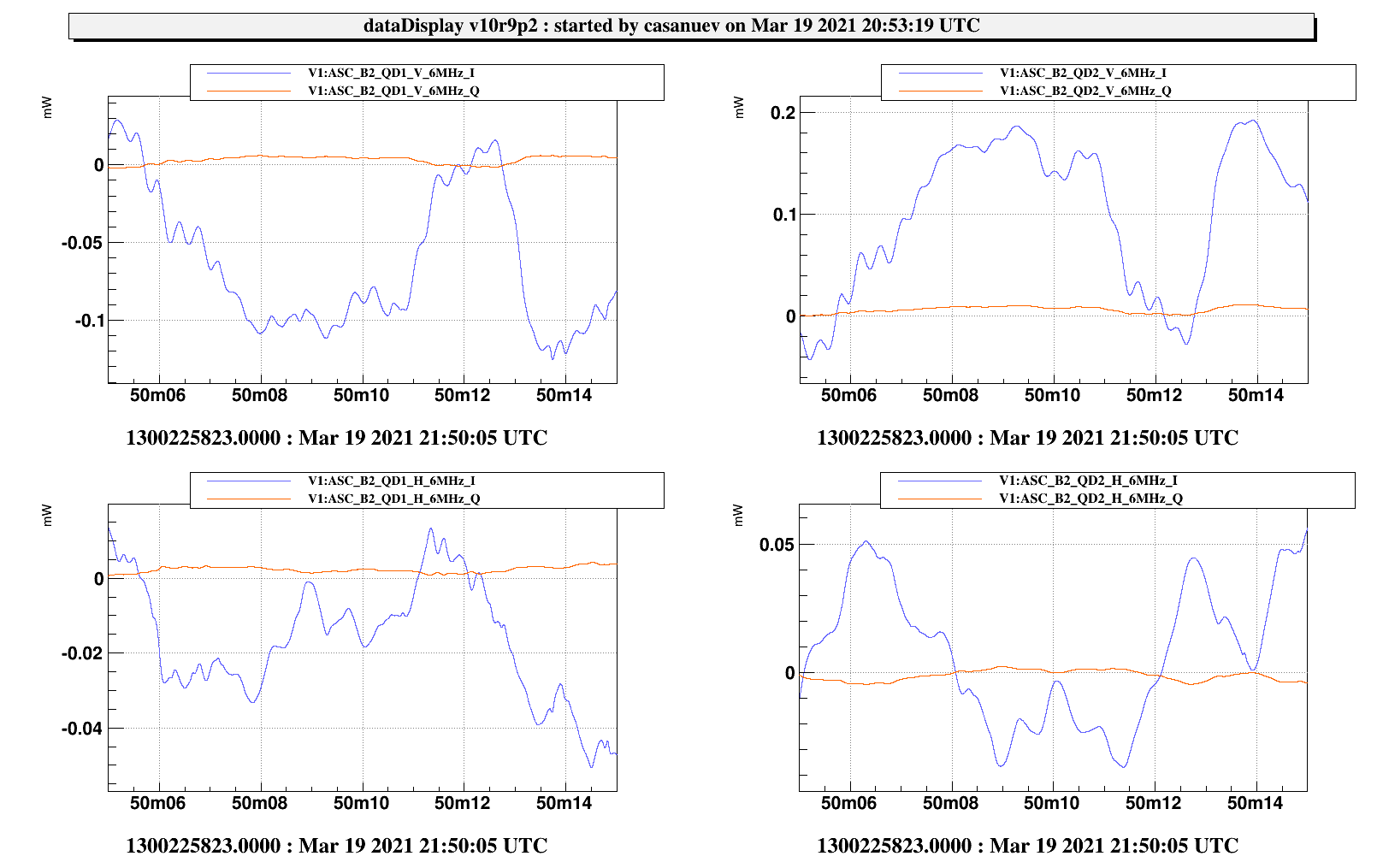
At 20.50 UTC the B2_6MHz QPDs demodulation phases were then tuned by applying offsets to the PR ty and PR tx signals, as shown in figure 10:
- QD1 V 0.78 rad QD1 H 0.78 rad
- QD2 V -0.2 rad QD2 H -0.3 rad.
The injection of a 3.5 Hz line on the PR tx and ty DOFs to calibrate the QPD's response was unsuccesful as it caused unlocks before being noticeable on the quadrant or optical lever signals. We were trying to use the usual line in the DSPs, however, when increasing the amplitude, some movement was visible on the LCs but it was definetly not a line. Probably we missed some logic step in the DSP.
However, we tried to use the 0 of the quadrants to align "by hand" the PR. The working points given by the quadrants demodulated signals actually bring the powers up, and to a good beam superposition in the camera, with a precision around 0.1urad (at least by hand) so at least the DC part seems to be a good error signal. The noise dominating the signals need to be understood if we want to use the signal up to higher frequencies.
After this, the PR and SR mirrors have been put in the MISALIGNED state and the arm cavities have been realigned and locked to the IR signal.

