Reports 1-1 of 1 Clear search Modify search
AdV-TCS (High reflectivity face sensing)
Lumaca, Nardecchia, Cavalieri, Dattilo - 12:51 Thursday 04 March 2021 (50979) Print this report
WI and WE HWS-HR temperature control system assembly and installation

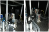
During the past two days we proceeded in the assembly of Peltier cells and temperature sensors on two HWS-HR, their cabling, proper work tests and their installation on optical benches. In figure 1, the two HWS-HR installed on WI (left, HWS-5) and WE (right, HWS-14) benches.

We decided to install HWS CCD with upgraded cooling fins on the WI bench, that seems to be more affected by temperature fluctuations, in order to test the efficiency of the temperature control.

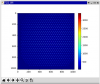
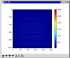
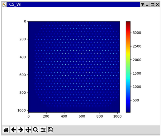
The images acquired by the cameras can be seen in figure 2 (WI) and figure 3 (WE).

The work to develop the digital part of the temperature control setup has already started by Alain (entry 50973). After that, the tests on the temperature control could start.

At present time, WI and WE HWSs are powerd ON; the corresponding SLEDs are OFF.

Images attached to this report
Comments to this report:
dattilo, nenci, cavalieri - 16:14 Monday 08 March 2021 (51010) Print this report

Details about electronics and cabling installation.

The installation of the electronic and the cabling needed for HWS temperature control loop is completed at TCS room and Terminal Buildings.

Each Hartmann sensor is equipped with two temperature sensors (PT100, classA), TE1 (inloop sensor), TE2 (out of loop sensor), and two Peltier cells, connected in series.

Peltier cells are driven by Kert power supply (see pict.1 for TCS room), remotely connected to a DAC channel.

DAC id boards and channel used:

TCS room: DAC_SN40 (DaqBox_SN31),  ch 04 for the NI driving and ch 05 for the WI driving

NE: DAC_SN27 (DaqBox_SN35),  ch 00 for the NE driving

WE: DAC_SN11  (DaqBox_SN49),  ch 00 for the WE driving

Temperature signals acquired by DAQ: (more details in #50973 by A.Masserot)

TCS_HWS_NI_TE1: ADC43, ch 02

TCS_HWS_NI_TE2: ADC43, ch 03

TCS_HWS_WI_TE1: ADC43, ch 04

TCS_HWS_WI_TE2: ADC43, ch 06

TCS_HWS_NE_TE1: ADC61 (DaqBox_SN35), ch 00

TCS_HWS_NE_TE2: ADC61 (DaqBox_SN35), ch 01

TCS_HWS_WE_TE1: ADC74 (DaqBox_SN49), ch 00

TCS_HWS_WEI_TE2: ADC74 (DaqBox_SN49), ch 01

Temperature sensors are acquired with a four wire circuits, by a commercial transducer (LKM214/1), 0..10V voltage output (see pict.3 for input and output connectors) .

The cables connecting the PT100 sensors to the transducer are  STPs AWG24, 18 m long (20m @ WI).

The cables connecting the peltier cells to their driver  are STPs AWG20, 18 m long (20m @ WI).

Example of temperature readings, available in pict.4.

Images attached to this comment
cavalieri, dattilo - 14:48 Saturday 15 May 2021 (51800) Print this report
As a precursor activity to the tuning of the control loop, we performed the characterization of the actuation part (DAC + driver + Peltier Cell).
We made measurement on HWM sensors of WI and WE. Each one has 2 Peltier cells, connected in serie, and feed by a power supply, whose current ouput is controlled by a DAC. The conversion factor is 2.5 [A/V].
We sent through the DAC a slow ramp up and down, with maximum values ​​up to 1.4V, equivalent to 3.5A on the peltier.
In the attaches plot is reported the voltage ramps, and teh corresponding temperature on the HWS (there are 2 T sensor on each HSW).
It can be see that increasing the current above a given value, the T stops to decrease and starts to increase, due to the fact that the power dissipated by the Peltier is larger than the heat that it is able to remove.
It can see a different thermal behaviour between WI and WE HWSs: the delta T reacheable at WI is 9C, at WE is 2.5C.
As a consequence, from the plot on the right colums, it can also be seen that the range for the correction is lower at WE (0.0-0.4V) than the one at WI (0.0-0.8V).
The reason is that each of the 2 peltiers at WI HWS has the original heat sink, provided by the TCS team. Instead at WE, with the permission of Viviana, we replaced the original heatsinks with new ones, more larger in size, with a lower thermal resistance.
Images attached to this comment
dattilo - 21:03 Thursday 08 July 2021 (52481) Print this report
On July 4th morning, I made the tuning of the PID controller of the WI HWS-HR temperature control system.
The tuning was based on the ZN method, with determination of critical period and critical gain in closed loop. (critical period = 129s).
The PID parameters have been inserted in the TCS-HWS-WI cfg file of the ACL process.
The loop has been closed on 10:39 UTC, and left closed for a long-term test (~ at least a couple of wks).
dattilo - 10:37 Wednesday 04 August 2021 (52750) Print this report
Some plots concerning the control loop at WI, active for about 27 days, and Tset=24C.
- fig 1: are reported the correction signal (TCS_HSW_WI_CORR), the controlled signal (TCS_HWS_WI_TE1, ie the temperature of the HWS), the temperature of the bench (ENV_TCS_HWS_WI) and the temperature of the CEB hall, measured with a sensor close to the N wall (ENV_CEB_N_TE6). It is also reported the hystogram of the controlled signal, made over a period of 27 days, where the computed rms value of 2.1mK represents also the accuracy of the control loop.
- fig 2 : comparison between the HWS temperature measured in 2 different periods: in July (control ON) and in May (control OFF). Just to mention that since with the contro OFF the temperature is around 30C, to make the comparison easier, an offset of 6.2C has been subtracted from the signal for the period with the OFF control.
Images attached to this comment
dattilo - 13:51 Wednesday 04 August 2021 (52765) Print this report
On the metal plate surrounding the Hartmann plate, in addition to the in-loop temperature sensor (WI_TE1) there is also an out of loop sensor (WI_TE2), used as a witness.
The trend of both sensors is shown in the attached figure. An offset of 0.3C has been added to the WI_TE2 signal to facilitate the comparison between the 2 signals. It can be seen that the non-uniformity in the metal plate is up to 40-50mK.
It needs to be checked with Viviana if this is acceptable or if it requires any improvement.
Images attached to this comment
Search Help
×

Warning

×