Reports 1-1 of 1 Clear search Modify search
AdV-SVS (Installation)
tacca, vardaro - 11:47 Tuesday 17 November 2020 (49955) Print this report
SC and Main PLL for FDS: SQZ Main Laser fiber coupling

We continued to couple the SQZ Main laser in the optical fiber. 

  1. We procured a set of variable resistors in order to change the Thorlabs photodiode load resistor
  2. We arrived to a 1V DC in the DC output of the Thorlabs photodiode with a load of 1 kOhm that correspond to a coupling of about 9%
  3. We started to move the lens in order to maximize the DC value read with the digital multimeter. We arrived to a value of about 1.7V that correspond to a coupling of about 14%
  4. We started to move the internal lens of the collimator. We reached a DC level of 3.6V that correspond roughly to a couploing of 27%

The SQZ Main laser pick off has a power of about 9.2mW. Up to now the coupled power is about 2.5mW that is splitted in 4 photodiode i.e. about 0.625 mW for photodiode. A reasonable value could be 1 - 1.5 mW for each photodiode, thus the coupling should be at least dounbled. 

In any case the actual power should be enough for the first tests of beat note detection.

Comments to this report:
vardaro, sequino - 23:22 Wednesday 25 November 2020 (50032) Print this report

We restarted from scratch with the fiber coupling

  • We checked the outuput of the fiber from PSL and we realized that the power was much lower than the last time. This is caused by the Fiber amplifier misalignment
  • We connected the Fiber from PSL to the input of the fibered 50:50 splitter. We connected one of the two output of the splitter to the collimator connector, then we measured the beam size exiting from the collimator. Wev realized that it was convergent.
  • We acted on the three collimator lenses in order to have a collimated beam at the output of the collimator. We performed the following measurement:
z [cm] dx[um] dy[um]
30 895 1.18
55.5 860 1.08
90 990 1.02
117.5 1.3 1.2
  • Starting from the PLL beam parameters at the output of the squeezer we designed a telescope in order to have a beam waist of 500um at the level of the collimator: i.e. 75cm after the output of the squeezer. We placed two lenses
    • f=1000mm @ 7.2 cm after the output of the squeezer box
    • f=500mm  @23.2 cm afrer the output of the squeezer box
  • With the beam profiler we cheched the beam size just before the collimator input and we measured about 500um
  • We started to couple the fiber and at the end of the process we measured 0.821V with a load of 1kOhm. We disconnected the optical fiber from one of the 4 photodiode and we measure 1.16mW of output power. We measured the IR power just before the collimaor and it was  8.9 mW. Thus we coupled (1.16*4/8.9)*100 = 52% of the input power. This coupling was reached putting the telescope on the table and without performing any iteration with the lenses. We did only one iteration by moving the collimator lens. Moreover we realized that the last time we forgot to tune also tha angle of the half-waveplate before the collimator.

Comments:

  1.  SQZ Main laser pick off beam power before the PLL box is 9.2mW. If we measure it after the half-waveplate we obtain 8.9mW
  2. The last time when we obtained 27% of coupling we measured with the tester 3.6V DC with 1kOhm of Load. This time we obtained 52% of coupling and we measure 0.812V. To be investigated
  3. With the frame for the plexiglass cover of the bench is impossible to close and open the PLL photodiode box once it is aligned. We need to misalign it each time we want open or to modify the cover of the box. Today we leave the box open because we need to complete the debugging of the Main PLL photodiodes
  4. Before installing the new telescope we put in the right place the two pillars of the plexiglass cover frame. We took in account their position in the design of the telescope (fig 2 and 3). Moreover we had to move by more than 10 cm the PLL photodiode box along the west direction. Now the remaining space just enough to connect and disconnect the LEMO6 connectors for the Photodiode powering.
Images attached to this comment
henning.vahlbruch - 8:17 Thursday 26 November 2020 (50035) Print this report
PLEASE do not use the squeezer box as a workbench!
vardaro, sequino - 15:07 Thursday 26 November 2020 (50041) Print this report

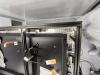
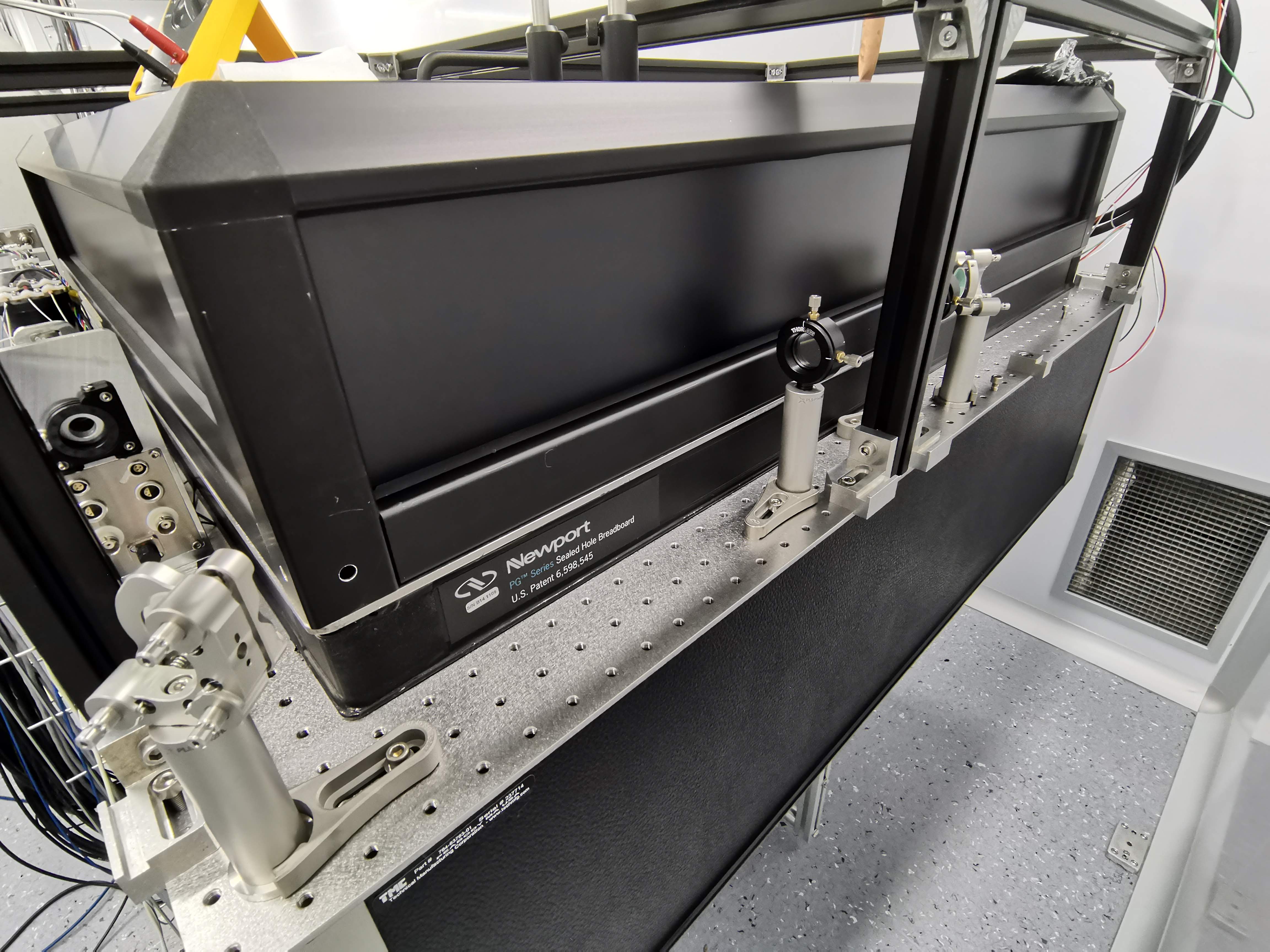
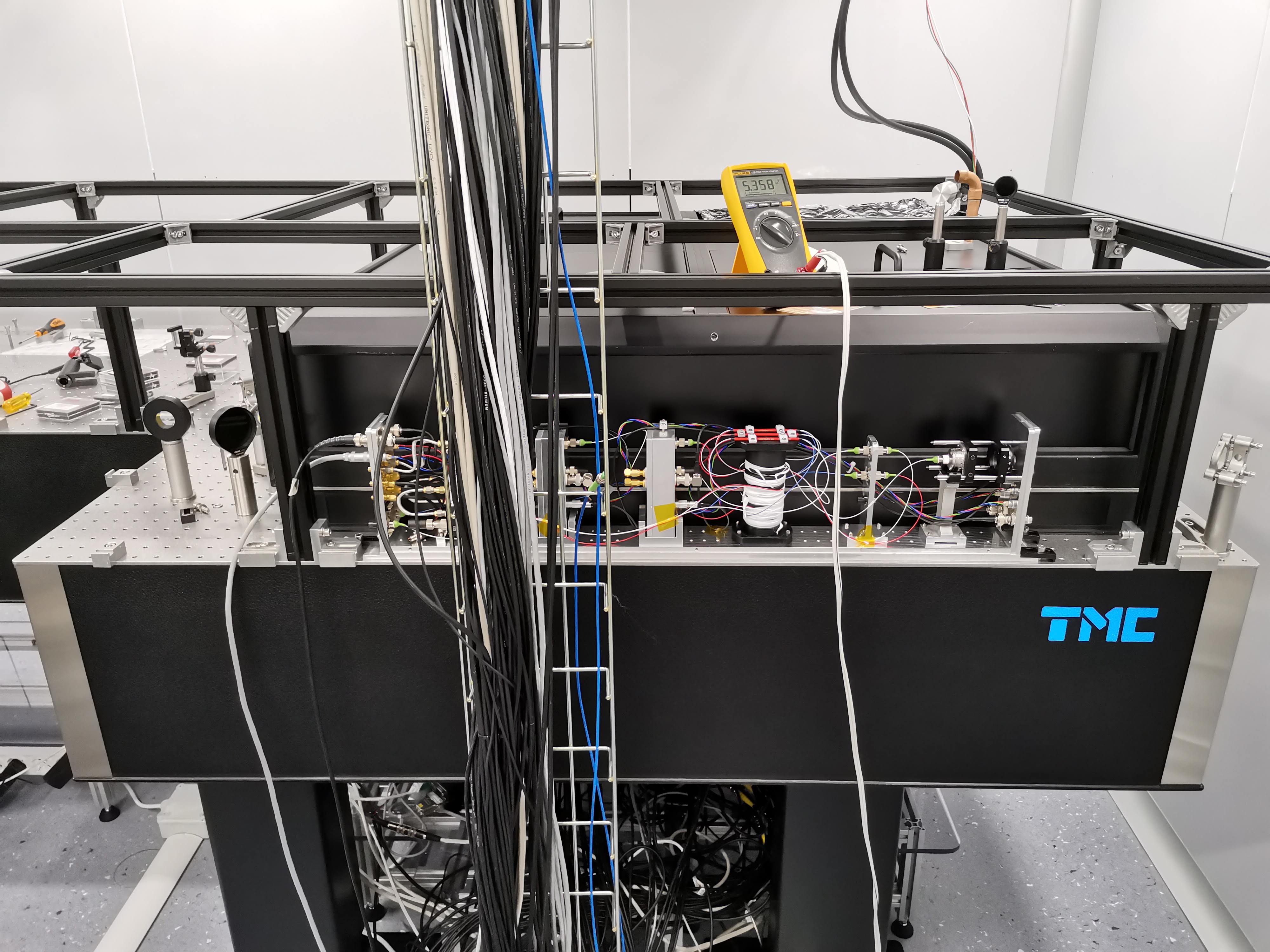
Today we continued to improve the coupling with the fiber:

  • we try to move the three screws of the collimator, but the process seemed to be no repeatable
  • we did some iteration by moving the f=500mm lens, but we did not change the matching too much (we moved the lens by about 5cm)

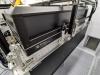
At the end of the process we read on the multimeter with 1kOhm 0.870V. Then we measured the coupled power at the output of all the fibers:

  • SC PD1 = 1.24mW
  • SC PD2 = 1.18 mW
  • Main PD1  = 1.24mW
  • Main PD2 = 1.18 mW

Then we remeasured the imput power: 9.3mW outside the PLL photodiode box and 9.0 mW Just before the collimator

Thus we coupled: (1.24+1.18+1.24+1.18)/9.0= 53.8% 

The coupling can be for sure improved but we think that the power is enough to start the first test in the beat note detection. At this point we realized that there was no light at the output of the fiber from INJ. 


We profit to measure the DC level with 1.2mW of coupled power also with the two photodiodes of the main PLL. We measured

  • Main PLL PD1: 1.230V with 1.24mW of power, 1.126V with no light
  • Main PLL PD2: 1.229V with 1.18mW of power, 1.106V with no light

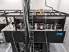
The offset of 1.1V without light is not expected. The electronic is the same used for O3 scientific run with two modification:

  • an additional op amp used as buffer for the DC
  • the sensor is no more the FD500 by fermionics but a Thorlabs pig tailed photodiode.

We have the impression that the problem can be caused by the buffer and if this is true the RF part of the photodiode should be not affected by this problem. Thus we want to wait the possibility to detect a beat note before unmount the photodiode from the box

Next steps:

  • detect a beatnote with the two thorlabs photodiode(5GUz of bandiwdth)
  • move the frequency of the SQZ Main laser in order to have the beat note around 80MHz (main PLL locking frequency)
  • Try to detect the 80MHz beat note also with the Main PLL photodiode. If it is detected with the expected level, try to close the Main PLL loop
  • At this point we can decide if open the photodiode or if we need to couple more power
grimaldi, montanari, zendri, - 0:11 Monday 11 January 2021 (50400) Print this report

The offset of 1.1 V measurend in the photodiode DC channel is given by the op-amp used as buffer: it generate a bias current that compress the signal at low intensity. The problem was resolved by changin the with a LTC6240.
We fix the power connector of the Fast Photodiode closer to the AEI box.

During the operation we lost the compling between the collimator and the beam coming from the AEI but we partially recover it. 

The procidure use for the recover was:

  1. By using the fiber from the interferometer pick off we generated a backward beam coming from the collimator and directed to the AIE hole.
  2. We put the collimator in a rest position by using screws X and Y( see Figure 1. for reference)
  3. We unscrew and move OPLL_MIR4 to coarse align the two beams
  4. We slightly misaligned the beam in order to see two spots on the laser viewing card using theta_z1 and theta_z2 of the collimator
  5. We use theta_z1, theta_z2, theta_z3 to coarse match the beam dimension between the two beams.
  6. We use Pitch and Yaw of  OPLL_MIR4 and screws theta_z1 and theta_z2 of the collimator for the fine alignment

After that we connect the photodiode next to the collimator to one of the 1st BS and optimize the coupling using the actuator as 4 and 5. In particular we saw that the distance between the collimator and the fiber was to big: the beam coming out from the collimator was divergent and we gain more signal screwing in the three screews. 

The fiber coupling optimization of the beam coming from the AEI box  requires further time. At present we leave  the system in the following configuration (80 MHz PLL detectors):

  • Main PD1 signal on DC channel 231 mV and 0.756 mW
  • Main PD2 signal on DC channel 239 mV and 0.753 mW 

but it could be increase more. Note that we did not check the power on the fast photodides and we did not check the HWP tuning


Images attached to this comment
Search Help
×

Warning

×