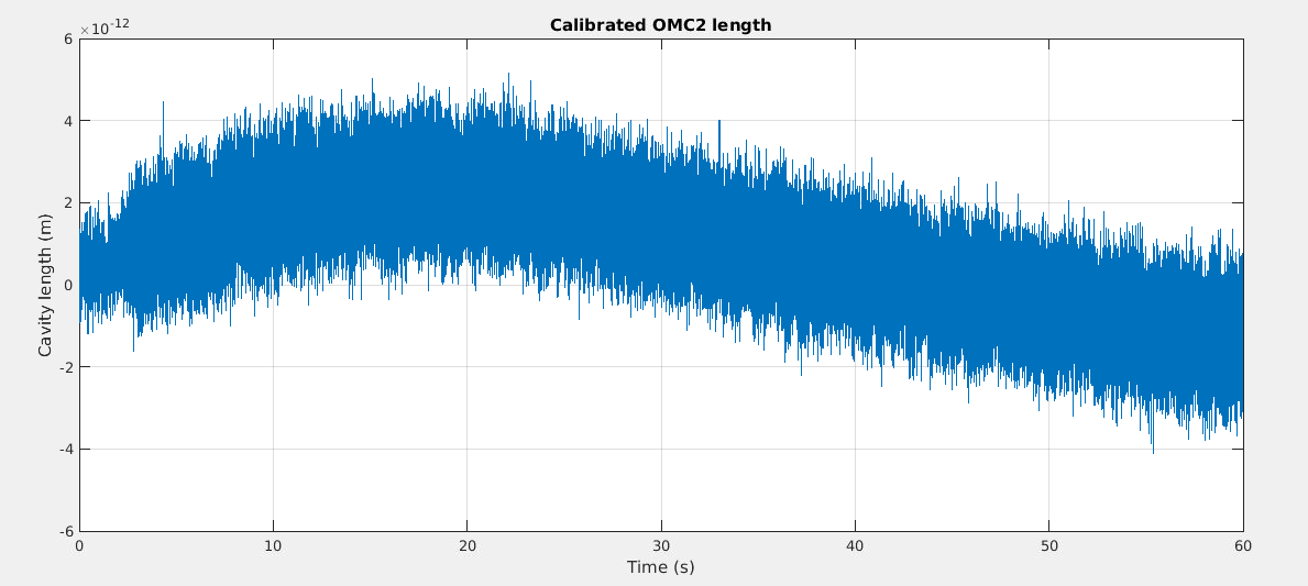
This afternoon shift was dedicated to new calibration measurements of the OMC with different PZT modulation amplitudes as a followup to previous results reported in entries 41021 and 41034. We also tested the effect of adding offsets in the OMC1 error signal, and we found that an offset equal to 1.6e-11 m minimizes the coupling of OMC length noise.
First, in order to be able to lock the 2 OMC, we reduced the amount of power transmitted by the Faraday Isolator by rotating the Faraday waveplate from its initial position -50900 to the detuned position -27950. This reduced the power measured on B1p and B1s1 by a factor 6.
Since last week results suggested that the amplitude of the PZT modulation was too large on OMC1 we started by reducing it by a factor 3 ( OMC1_PZT_amp(0.1) ). Then we took data while injecting the calibration line at 119 Hz:
- Calibration line injected on OMC1: start: 1207495961 - stop: 1207496021
- Calibration line injected on OMC2: First segment : start: 1207496021 - stop: 1207496082 / Second segment : start: 1207497100 - stop: 1207497160
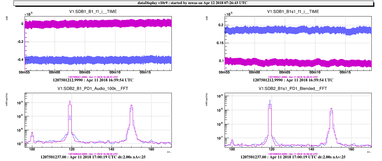
We then noticed that the demodulation phase of B1_f1 was not properly tuned and we corrected it in order to obtain a bit more than a factor 100 of separation between the I and Q demodulated signals. The loop gain was reduced to avoid loop oscillation. New calibration data were taken after this demodulation phase adjustment:
- Calibration line on OMC1: start: 1207499311 - stop: 1207499371
- Calibration line on OMC2: start: 1207499371 - stop: 1207499431
At this point we repeated calibration measurements for different values of offset injected in the error signal of OMC1:
- OMC.OMC1_offset = 1e-5
- Calibration line on OMC1: start: 1207499751 - stop: 1207499811
- Calibration line on OMC2: start: 1207499811 - stop: 1207499871
- OMC.OMC1_offset = 1e-4
- Calibration line on OMC1: start: 1207500007 - stop: 1207500067
- Calibration line on OMC2: start: 1207500067 - stop: 1207500127
- OMC.OMC1_offset = 5e-5
- Calibration line on OMC1: start: 1207501213 - stop: 1207501273
- Calibration line on OMC2: start: 1207501273 - stop: 1207501333
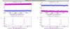
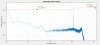
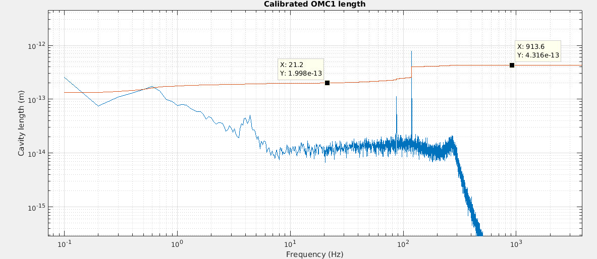
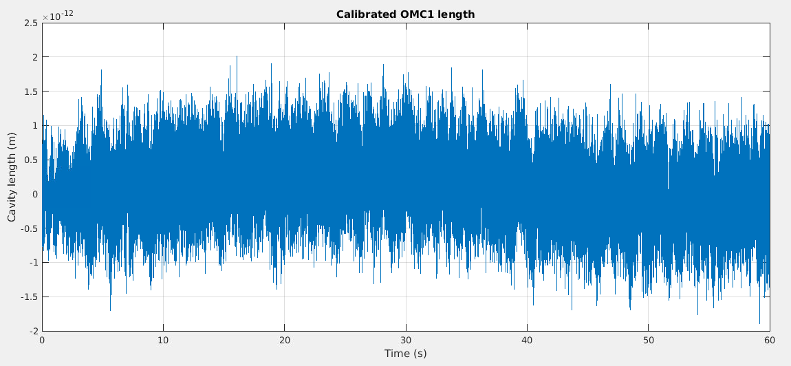
As explained in entry 41034 , the height of the 1f calibration line at 119Hz in the error signal can be used to estimate the total RMS of the locking accuracy. A quick look at the data indicates that this total RMS is reduced by an order of magnitude when injecting an offset equal to 5e-5 (corresponding to 1.6e-11 m once calibrated). This will be further investigated.
Keeping this offset of 1.6e-11 m in the error signal, new calibration data were taken after reducing further the PZT modulation amplitudes in both OMC (OMC1_PZT_amp(0.03) and OMC2_PZT_amp(0.003).
- Calibration line on OMC1: start: 1207502261 - stop: 1207502321
- Calibration line on OMC2: start: 1207502321 - stop: 1207502381
These lower modulation amplitudes were left as permanent setting.
After unlocking the OMC2, we performed some temperature scans of OMC2 (with OMC1 still locked) in order to have an independant way of cross-checking the calibration. The following data were taken:
- Scans around the TEM00, nominal temperature set point: start: 17:39:00 - stop: 17:44:00 utc
- Scan of 2 full FSR: start: 17:45:00 - stop:17:57:00 utc
- Scan around TEM00, TEM01, TEM02: start: 17:57:50 - stop: 18:01:00 utc
After unlocking the OMC1, some scans were also performed:
- Scan around TEM00: start: 18:05:30 - end: 18:09:00 utc
- Scan of full FSR: start: 18:09:30 - end: 18:17:00 utc
At the end of the shift, the rotator of the Faraday Waveplate was put back to a position (-47150) maximizing the power on B1p and B1s1.
Results of the analysis of these date will be posted later.

