From -50900 steps to -21690 this reduces the power by a factor 6.
After fixing some typos locked both OMCs using the doubly normalized error signal as an intermediary step to increase the locking speed.
Could lock without issues with a ramp that is 6 times faster than what was used last year.
An attempt at calibrating the error signals
OMC1 calibration start: 1207065086
OMC1 calibration stop: 1207065146
OMC2 calibration start: 1207065146
OMC2 calibration stop: 1207065206
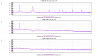
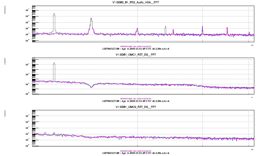
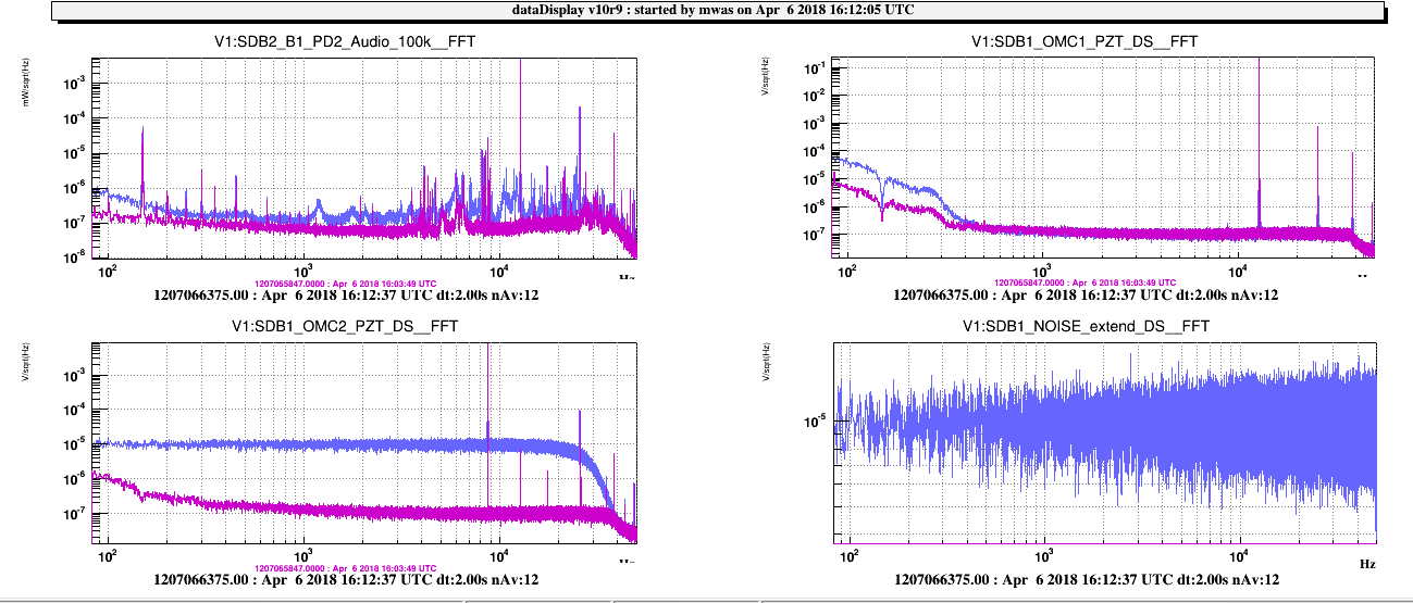
Figure 1 spectrum of B1 PD and PZT injection of 0.03V into OMC1, oddly enough the 1f is higher than the 2f signal in B1 by factor 100
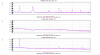
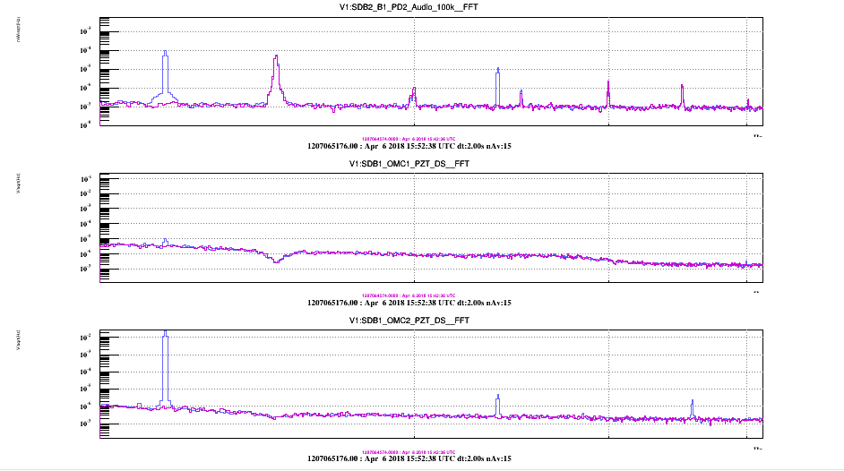
Figure 2 spectrum of B1 PD and PZT injection of 0.03V into OMC2, oddly enough the 1f is higher than the 2f signal in B1 by factor 10
Is there an offset in the OMCs lock?
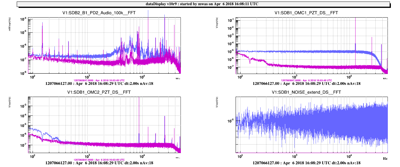
16:08 UTC (2min) injecting 1e-5 V into OMC1 PZT up to 50kHz, Figure 3
16:12 UTC (2min) injecting 1e-5 V into OMC2 PZT up to 50kHz, Figure 4, there are some peaks at a few kHz, but this is probably down conversion
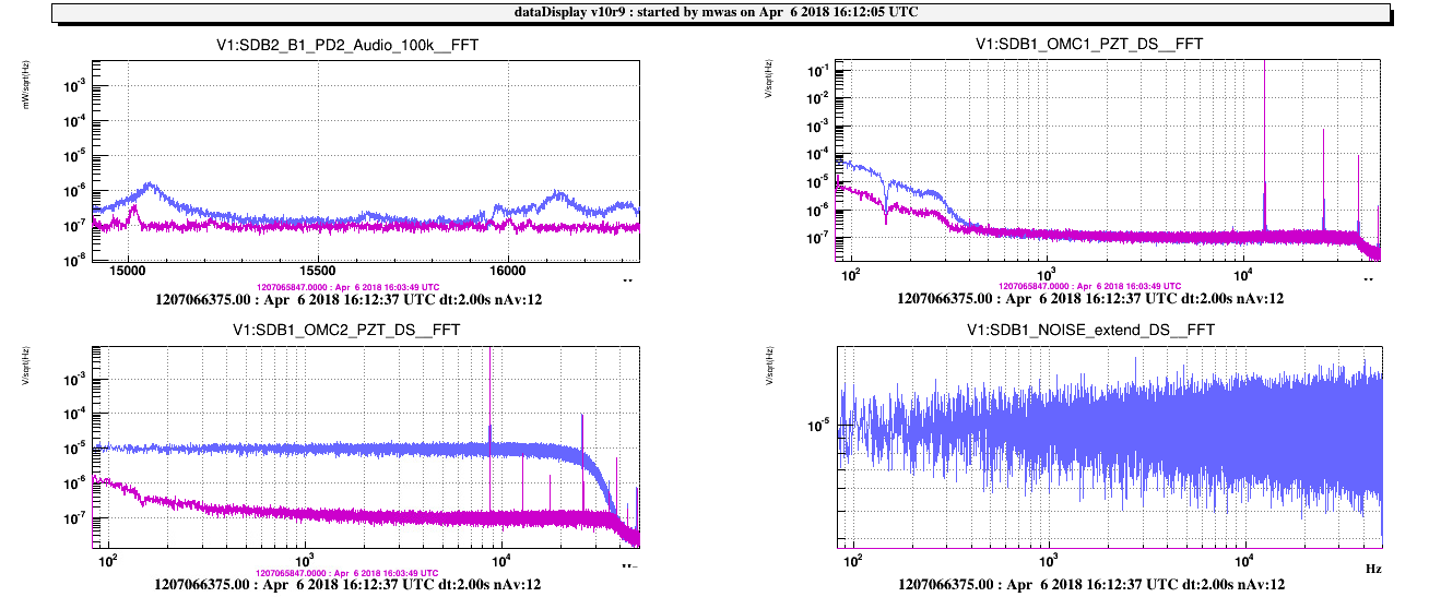
Changed OMC2 modulation frequency to 15'569 Hz (a prime number), a relatively quiet place in resonance spectrum, Figure 5.
Made another calibration run for the OMCs
OMC1 calibration start: 1207068156
OMC1 calibration stop: 1207068216
OMC2 calibration start: 1207068216
OMC2 calibration stop: 1207068276
17:39 UTC (8min) noise injection into OMC1 loop after changing the PZT filter shape
17:49 UTC (8min) noise injection into OMC1 loop with PZT old filter
Figure 6, comparison of the two, some unnecessary phase margin has been sacrificed to add a lot of low-passing above a few Hz, note there is only a factor 2 gain margin. But the PZT is used in loop only with the signal that is power and modulation depth normalized, so that should be ok.
Made the same change of filters for OMC2.
Another calibration injection after all these changes
OMC1 calibration start: 1207075177
OMC1 calibration stop: 1207075237
OMC2 calibration start: 1207075237
OMC2 calibration stop: 1207075297
Added a constant IMPINGING_POWER to normalize the doubly normalized error signals, this should allow much easier switching between various powers
Put back the Faraday rotator to -50900, which still corresponds to maximum throughput.
Changed the IMPINGING_POWER parameter from 17.5mW to 96mW, and the OMC1 lock worked well.
The calibration times will be analyzed later on.

The amplitude of the modulation in meters can be measured from the height of the 2f line (2*119Hz = 238Hz).
The starting point is the Airy peak formula:
dP/P0 = 1/[1 + (2 F/pi)^2 sin^2(2 pi l / lambda)] - 1
which for a monochromatic small modulation simplifies to
dP/P0 = - (4 F)^2 * (l / lambda)^2
which means that the RMS of the length modulation l_mod in meters is:
l_mod = lambda/(4*F)*AS_PD(at mod frequency)/P0
where AS_PD is the amplitude spectrum of the PD signal (ie sqrt(PSD_PD*dF))
comparing this to the amplitude spectrum density of the calibration line as seen in the error point spectrum allows to calibrate the error point into meters.
The same can be done for the high frequency (10-15kHz) dither line to estimate its modulation depth.
In addition, looking at the height of the 1f calibration line at 119Hz, we can estimate the total RMS of the locking accuracy, as the linear coupling is:
l_RMS = lambda^2/l_mod/(32*Finesse^2)*AS_PD(1f)/P0
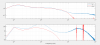
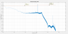
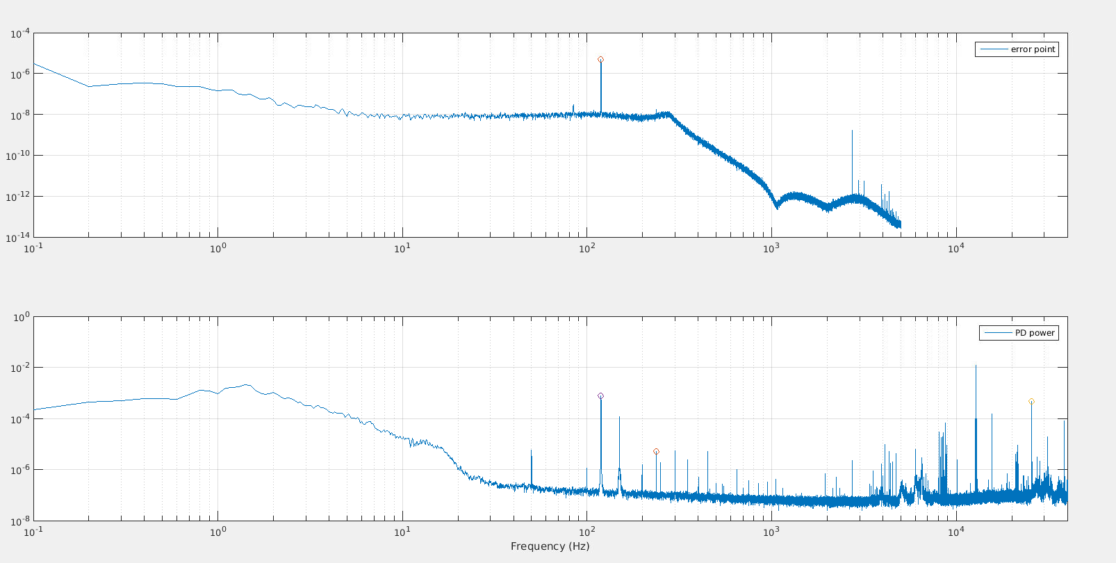
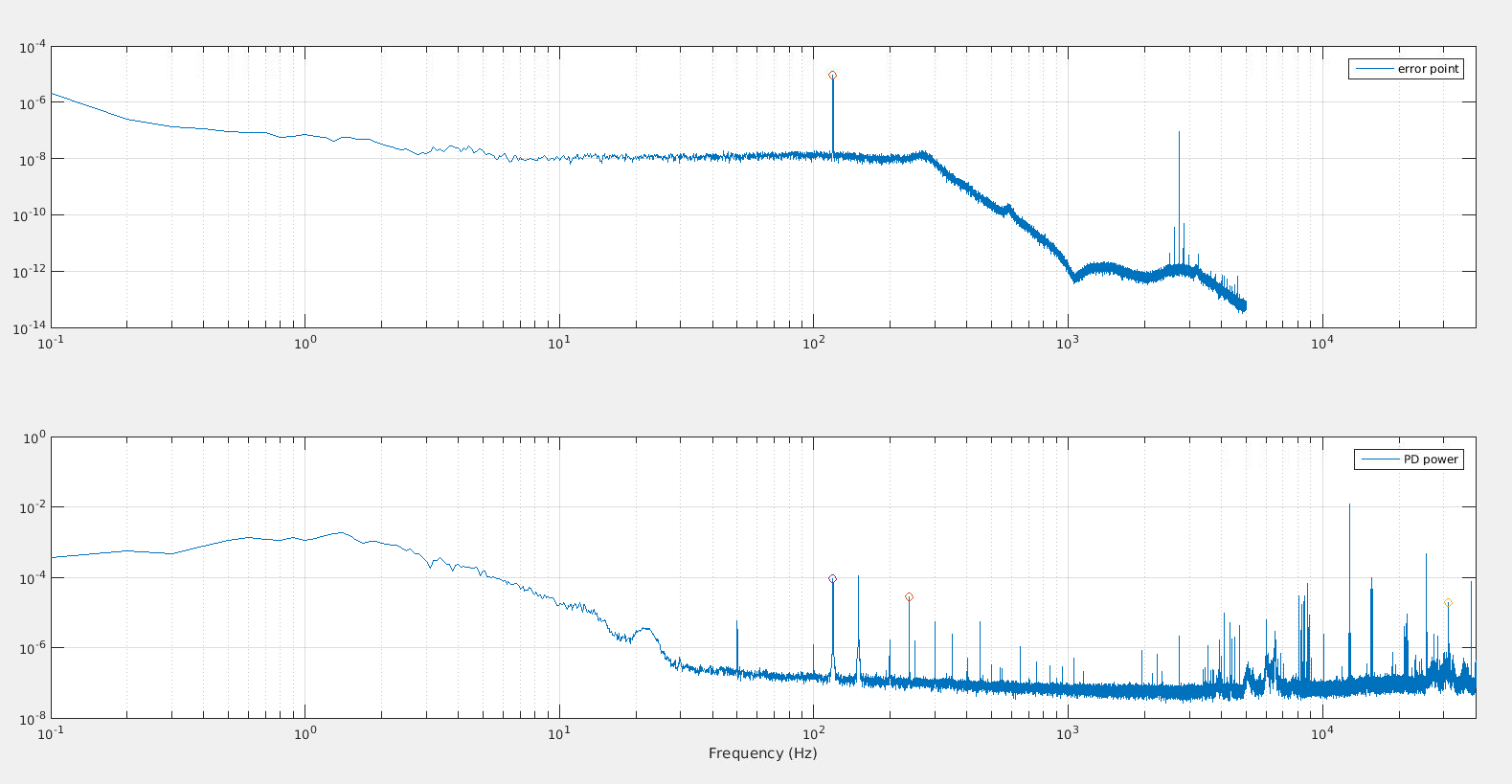
Figure 1 shows the 4 spectrum data points from the error point and PD used for OMC1 and Figure 3 is the same for OMC2.
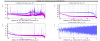
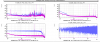
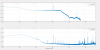
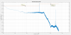
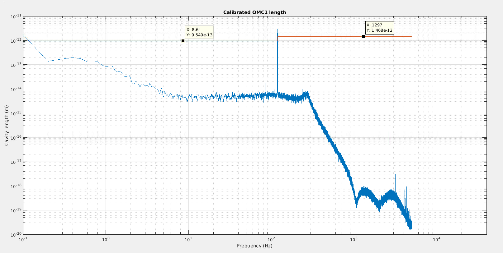
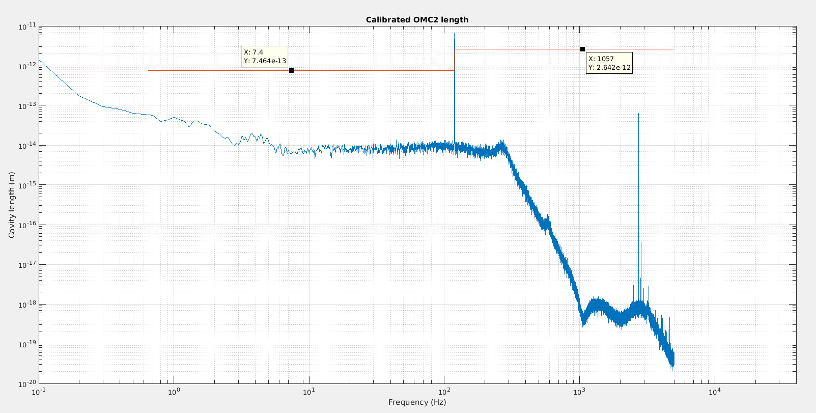
Figure 2 shows the calibrated error spectrum and its RMS for OMC1 and Figure 4 for OMC2.
For OMC1 the calibration is
calib_factor = 5.6908e-07
the calibration modulation depth
l_mod = 9.0512e-13 m
the error point dither modulation depth
l_err_mod = 8.4857e-12 m
and the total estimate RMS is
l_RMS = 6.4433e-11 m
this is much higher than expected, from figure 2 the measured RMS below 200Hz is 1.47e-12 m which added in quadrature to the high frequency dither yields 8.62e-12m, so most of the RMS is not explained. The PZT actuation gain is 5e-11 m/V at 119Hz and 5e-11 m/V at 13kHz.
For OMC2 the calibration is
calib_factor = 7.0264e-07
the calibration modulation depth
l_mod = 2.0625e-12 m
the error point dither modulation depth
l_err_mod = 1.7311e-12 m
and the total estimate RMS is
l_RMS = 3.4853e-12 m
this is about where it should be, from figure 4 the measured RMS below 200Hz is 2.64e-12 m which added in quadrature to the high frequency dither yields 3.16e-12, so most of the RMS is explained. The PZT actuation gain is 1e-10 m/V at 119Hz and 3e-10 m/V at 15kHz.
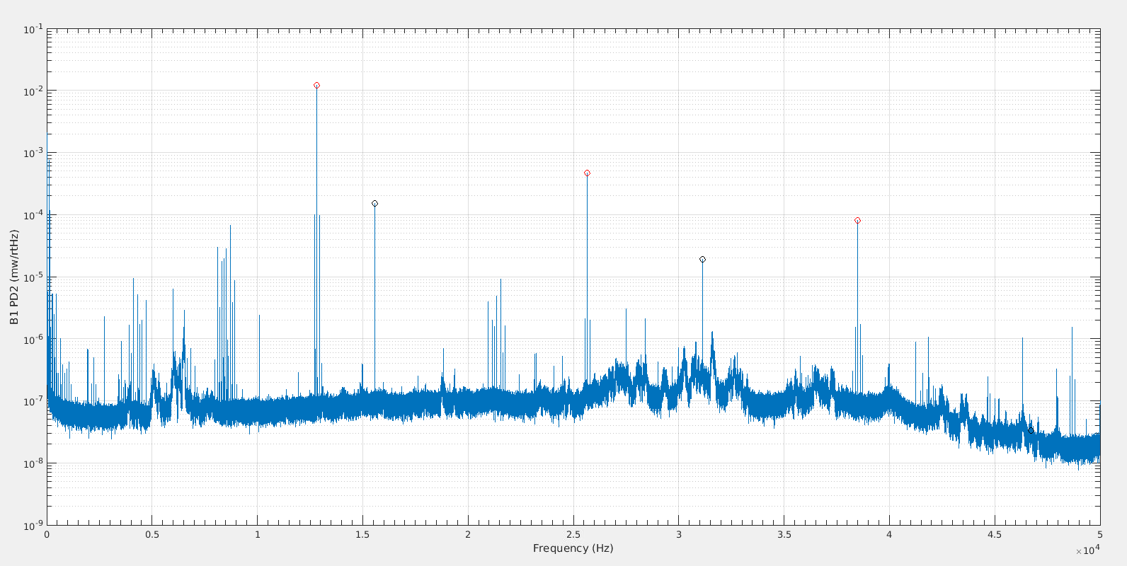
Figure 5, looking at the high frequency PD spectrum, the OMC1 modulation 1f, 2f, 3f are shown in red, and for OMC2 in black. The OMC2 3f line is buried in noise, but for OMC1 it is quite high. So maybe something is saturating in the dither actuation which could explain the excess length noise coupling in OMC1.
At the next opportunity we should make these calibration measurements, and an OMC scan at the same time. To compare that the two methods of calibration give the same result. Also, the OMC1 line should be reduced to get rid of the high harmonics and we should explore with lock offsets and calibration line heights to check that the calibration method really works (doesn't depend on the calibration line height) and that the total lock RMS estimate is correct. Note that I haven't paid much attention for conversion from modulation depth to RMS and for power spectral leakage, so the value here might be wrong by factors ~sqrt(2).
The scripts to analyze the calibration are in /users/mwas/OMC/OMC_calibration_20180406
