* by increasing the OMC1 lock offset the OMC loop feedback shows up and some mechanical resonances above 3.5kHz, but no change in the 4kHz cross-coupling between OMC1 and SDB1 LC lines
* this means is the cross-coupling is not a length noise on the OMC (due for example to electrical couplings to the PZT actuation)
* the cross-coupling is bilinear, linear both with OMC1 PZT and with SDB1 LC lines amplitude
* angular misalignment don't have much impact, only showing a 5.6kHz horizontal mechanical mode and increased 50Hz coupling
------
ITF can't reach LOW NOISE 3 yet, so using a single bounce from the NI mirror and OMC1 only locked instead.
15:18 (1min) reference data
15:20 (1min) 2e-4 offset on OMC1_err
15:22:30 (2.5min) 2e-3 offset - bumps at 5kHz and 6kHz appear
15:26:30 (1min) 4e-3 offset
15:30 (2min) 8e-3 offset
15:34 (9min) 16e-3 offset - the transmitted power is lower by ~30% than on the maximum
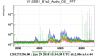
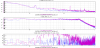
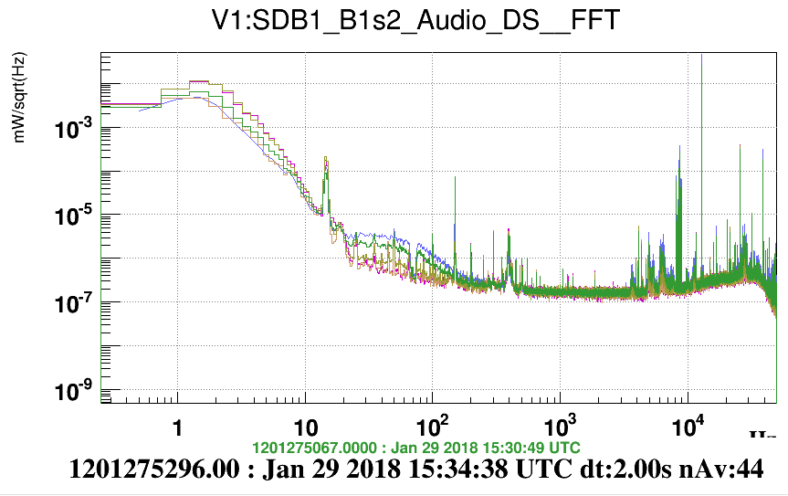
Figur 1, there are bumps between 3.5kHz and 8kHz that are increasing with large offsets, these are probably longitudinal mechanical modes of the OMC
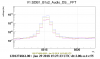
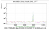
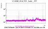
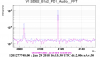
lines at ~4kHz (OMC1 PZT minus SDB1 LC) are not moving, lines at 8kHz (SDB1 LC) are increasing (linearly?) once the offset is large (figure 2 and 3)
line at 12831.3 Hz or its mirror at 7168.7Hz is increasing (linearly?) with the offset, this is expected as that is a pure length noise injection
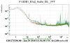
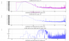
Figure 4 and 5, there is broad-band bump at 10-100Hz, due to OMC feedback of sensing noise (we are more sensitive to length noise when the offset is large)
=> the lines at 4kHz are not a length noise, and OMC sensing noise is dominating length noise between 10-100Hz
removed the longitudinal offset around 15:45 UTC
Leaving the B5 beam drift control on, and putting an offset in the error signal to misalign SDB1
15:51 (1min) 10um (comparable to the RMS) offset on B5 QD2 H
15:54 (2min) 40um offset, B1s2 power goes down by 5%
15:57 (3min) 80um offset, B1s2 goes down by 10%, bump at 5.6kHz, 50Hz harmonics are much larger (Figure 6)
16:02 (1min) 0um offset on QD2 H, and 40um offset on QD2 V
16:04 (1min) 80um QD2 V offset, the 450Hz (50Hz harmonic) is high,
16:06 (2min) 120um QD2 V offset, similar to 80um case, bump at 5.6kHz is not there, probably 5.6kHz bump is a horizontal resonance of the OMC
removed angular offset
16:15 (2min) UTC increased OMC1 PZT dither amplitude from 0.3V to 0.6V, 4kHz lines increase by a factor ~2 (Figure 7)
16:18 (2min) UTC decreased OMC1 PZT dither amplitude from 0.3V to 0.6V, 4kHz lines decrease by a factor ~2
put back the OMC1 dither to normal 0.3V
16:22 (3min) UTC reduced SDB1 local control lines from 2V to 1V, the 4kHz and 8kHz lines decrease by a factor ~2
put back SDB1 LC lines to 2V
16:30 (1min) reduce OMC loop gain by a factor 2, bump at 15Hz goes down
16:33 (1min) increased OMC loop gain by a factor 2, bump at 15Hz goes up
put back OMC loop gain to nominal
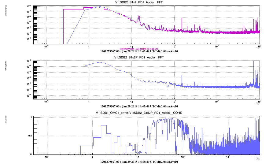
16:38 UTC turned on B1s2P and B1p_PD1
Figure 8, on B1s2P a bump like at 10-100Hz from OMC loop sensing noise is quite visible and coherent. This is make sense as for the P-polarization the OMC is not on resonance, but not very far from it, so the situation should be similar to the case of s-polarization with a large offset
But then the light transmitted by the OMC has a quadratic response to length changes (the Airy peak), which causes the line mixing and creates the ~4kHz lines.
The mixed lines will not depend on the lock offset as the offset changes the slope of the Airy peak but not its curvature.
So for example for two length perturbation x and y, the transmitted light is:
T = 1/(1 + (x + y + offset)^2) ~ 1 - x^2 - y^2 - offset^2 - 2*x*y - 2*offset*x - 2*offset*y
the height of the 12kHz and 8kHz changes linearly with the offset, but the 2f lines and the cross-talk line doesn't depend on the offset
A check of that idea would be add intentionally another line on the OMC1 PZT and check that height of the cross-coupling, 1f and 2f is consistent with the SDB1 LC lines present on the PD signal.
The reason why the SDB1 LC lines couple with the OMC PZT are still unclear, especially because the line mixing changed by a factor 10 after removing the OMC covers.
So it is unlikely the coupling happens on the long cables going down the suspension.
One possibility is that the electrical insulation of the PZT is damaged, and current is leaking into the floating mass of the SDB1 bench.
This could be tested by comparing the resistance between the two PZT pins, and between one of the PZT pins and the screw tightening it during the new output Faraday installation.