This evening we performed the following tests on the suspended benches, to investigate further scattered light noise and the hypothesis of beam jitter on SDB1.
1. Injection of low frequency line on SDB1 suspension to measure scattered light coupling factor:
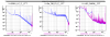
We injected a sine signal at 0.1 Hz on the top of the SDB1 suspension along the longitudinal degree of freedom:
- Line amplitude = +/-15 um ; Start = 17:29:48 utc, Duration = 300 s
- Line amplitude = +/-30 um ; Start = 17:36:33 utc, Duration = 300 s (Fig.1)
- Quiet data: Start 17:46:30, Duration = 300 s
As shown in Fig.1, the scattered light arch is well visible in DARM. The coupling factor will be measured off-line and compared to the one obtained with the measurement of June 15 (logbook 38034).
2. Injection of low frequency line (0.1 Hz) on other suspended benches:
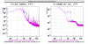
We repeated a similar procedure on SNEB, SWEB and SPRB, by injecting a line on the top of the mSAS suspension along the longitudinal degree of freedom:
- SNEB: Line amplitude = 100 (in SBE config file) ; Start = 20:18:27 utc, Duration = 120 s (Fig.2)
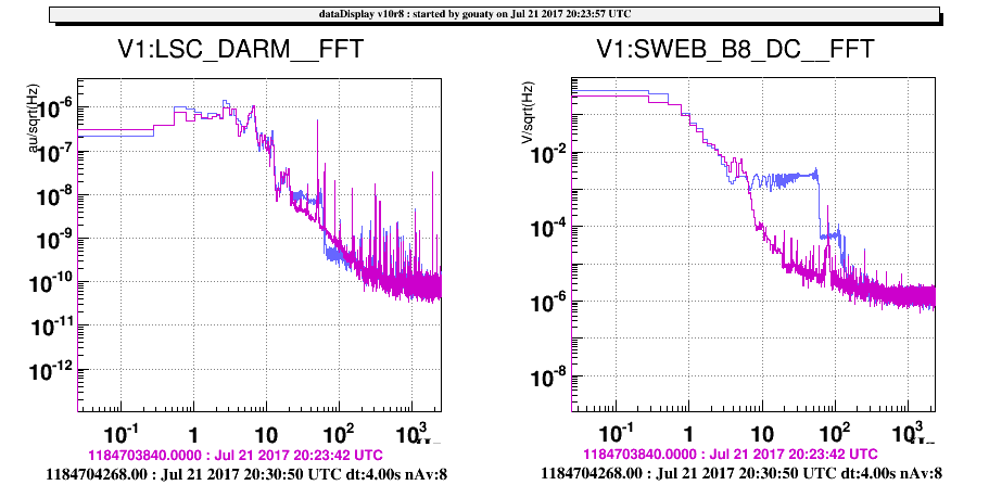
- SWEB: Line amplitude = 400 (in SBE config file) ; Start = 20:28:44 utc, Duration = 120 s (Fig.3)
- SPRB: Line amplitude = 400 (in SBE config file) ; Start = 20:40:47 utc, Duration = 120 s
As shown in Fig.2, a coupling of SNEB scattered light is now well visible in DARM when we excite this bench (this was not noticed when similar injections were performed a few months ago, but it could be because the sensitivity as not as good at that time). On Fig.3 we can see that a coupling of SWEB scattered light to DARM is also visible when the bench is excited but the amplitude of the scattered light is lower.
When injecting the low frequency line on SPRB it was not possible to see any coupling to DARM (some was visible on B4_DC). This confirms observations done a few weeks ago.
More analysis to come to estimate the scattered light coupling factors from SNEB and SWEB.
3. Exciting SDB1 with mirror picomotors:
As planned, we tried to excite SDB1 noise by applying 1 step on the bench picomotors. We first tried to apply 1 step in Z on the OMC2 translation stage which unlocked the interferometer. We repeated this test with SDB1_Mmot2_TY (the last mirror before the OMC1), which again unlocked the interferometer. We then repeated this test on SDB1_M2 which is far away from the OMC. Again the interferomter unlocked when applying the 1 step. Unfortunately it seems that as soon as we actuate a picomotor on SDB1 by a single step we loose lock, thus this kind of test cannot be performed.
4. Misaligning SDB1 bench:
After switching off the SDB1 drift control, we misaligned the SDB1 bench in TY around 20:00 utc to check the impact of this action on DARM. We repeated a similar test on TX around 22:05 utc. The interpretation of this test is not straightforward because a misalignment of the bench induces larger fluctuations on B1p, which is know to be correlated with larger structures in DARM. Further analysis may be needed, but the preliminary conclusion is that the changes observed in DARM when these misalignments were too marginal with respect to what we would expect if the resonances in DARM were due to beam jitter at the input of the OMC.
