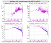
Today we wanted to check if there is room for improvement on the boost filter for the SSFS without spoiling too much the digital noise performances and the gain margin we have, and to reduce some contributions to the noise in the 10-30 Hz band. In order to do so, we lowered the frequency of the three single zeros in the boost filter from 50 Hz to 20 Hz (on both branches), and this should give us an improvement of a factor ~15 in such range. This is the summary of our findings:
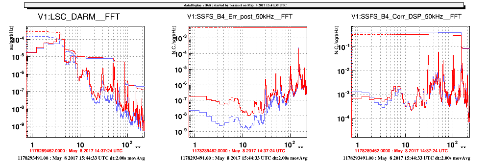
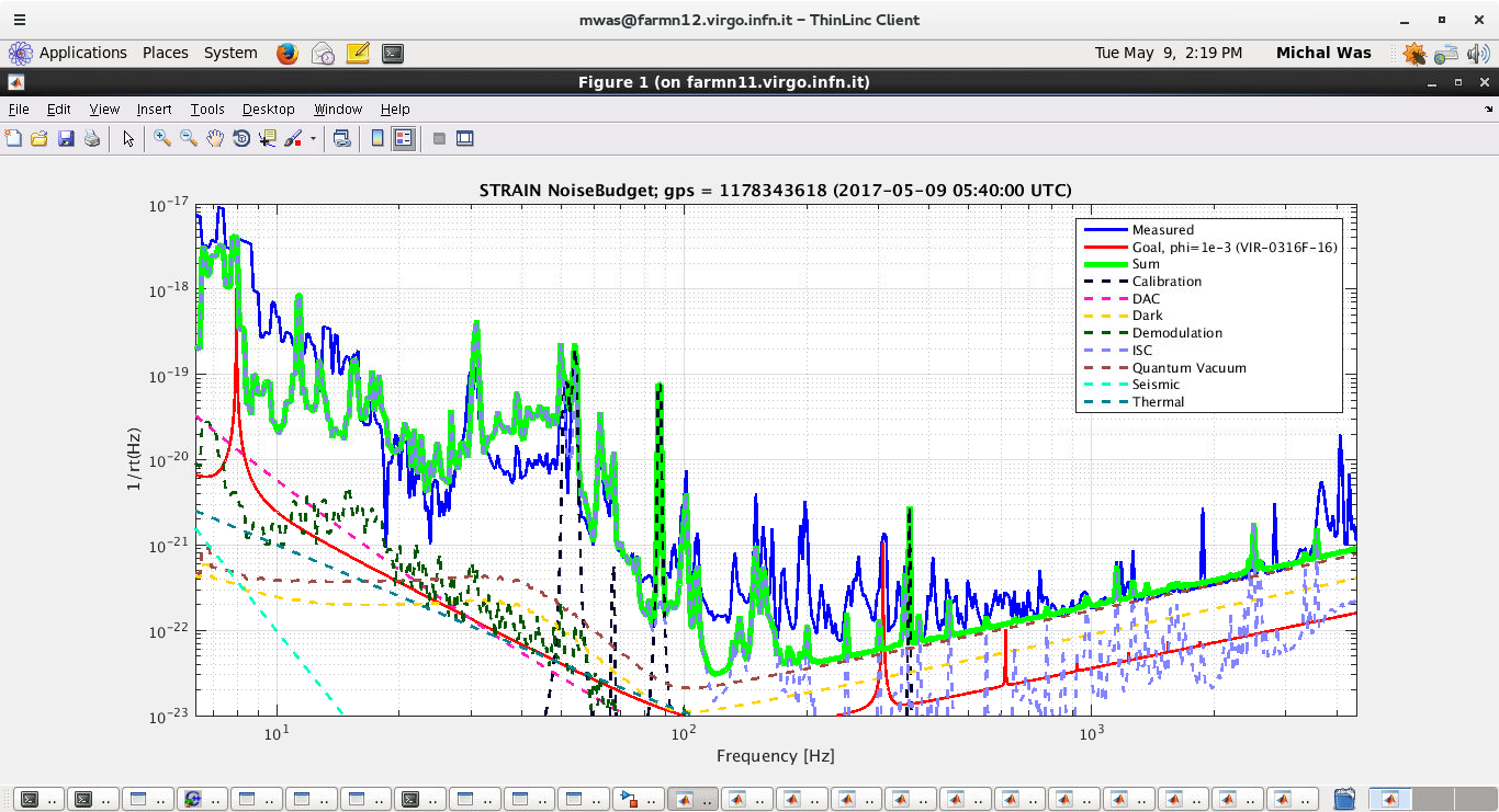
- the boost filter is working as expected, as one can see in Figure 1, with a good improvement at low frequenc; this did not result in any macroscopic change in the digital noise, anf the different levels of the digital noise during the two measurements are due to the fact that the two measurements were done in different times during a "lifecycle" of the boost filter, which gets reset every 20 minutes (a more appropriate solution, based on the ratio of the rms of SSFS_Corr and SSFS_DigitalNoise is in the works);
-
however, we found out that this reduced our gain margin:
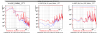
- the first time we used the new boost, the current gain of 900 was too high, as we saw some gain peaking at 10 kHz; note that as of now the UGF of the SSFS loop seems to fluctuate greatly, about an order ~2, so the gain peaking is not a constant or predictable feature;
- reducing (afterwards) the gain to just 800 seemed to cure this behaviour, as the peak disappeared;
- however, although with very poor statistics so far, we could observe that it was not possible to engage the boost filter already with the lower gain, which is something that surprised us, as the difference is quite tenuous; as a subsequent noise injection seems to prove, we already have a UGF quite close to 10 kHz, but apparently we cannot lower it too much using the gain, as we needed to increase it in order to engage the boost in the first place; we are not limited by frequency noise yet in this frequency range, but maybe we could overcome this low margin by moving the SSFS to full bandwidth, i.e. 1 MHz;
- we tried to keep the new boost filter to collect some more statistics, but unfortunately the ITF unlocked too frequently when trying to engage the boost filter, so we reverted the configuration to the old boost filter; as we were checking the unlocks we noticed that switching between filters in the SSFS DSP happens without any ramp (or at least this is what happens to the B4_selectFilter, which is the one that manages the transition on the MC branch), and with a big glitch in the signals;
- some conclusion we may drive is that the new boost filter is not critical by itself, but it triggers some unexpected behaviour in the logic/transition;
- the currently scarce gain margin we have, however, seems real and not related to the filte transition: a gain of 400 was too low to engage the boost, and a gain of 1200 already unlocks the ITF;
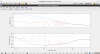
- as we reverted to the old filter (which is the one we've been using in the C8 Run), we saw that the only glitch happening during the transition is in DigitalNoise_Corr, while we don't see anything in both SSFS_Err and SSFS_Corr; the glitch is DigitalNoise_Corr is actually expected, as the filter transition triggers a filter reset beforehand, and the glitch we see is the same we observe every 20 minutes during the reset, and it gets suppressed by the noise subraction inside SSFS;
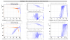
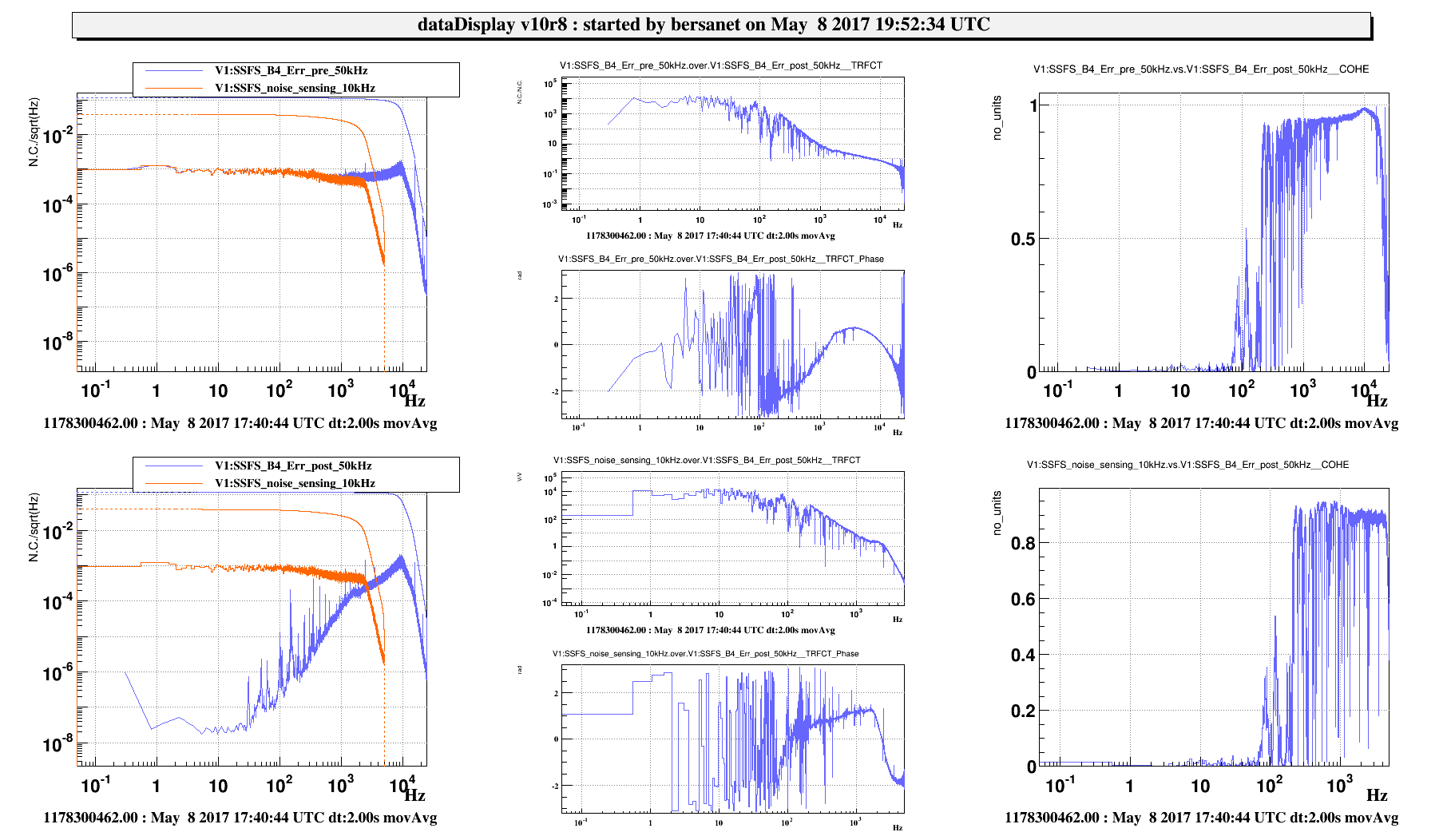
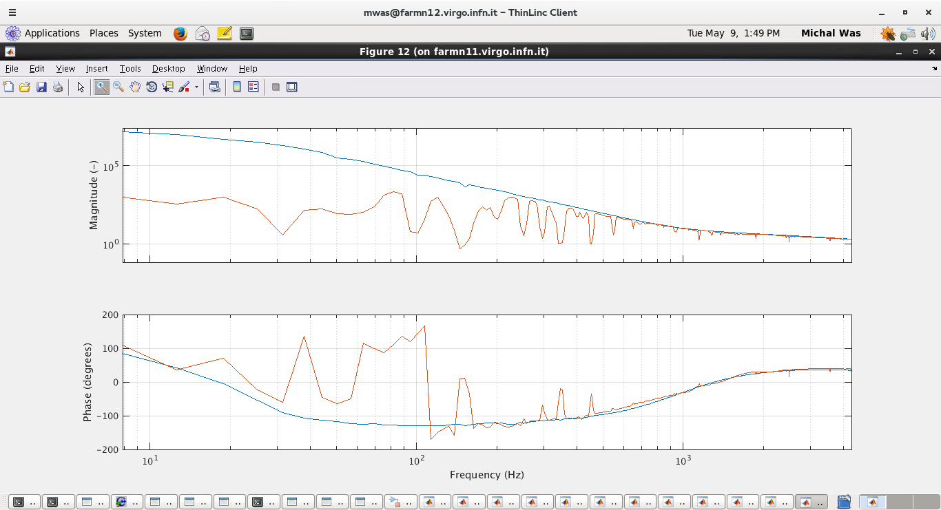
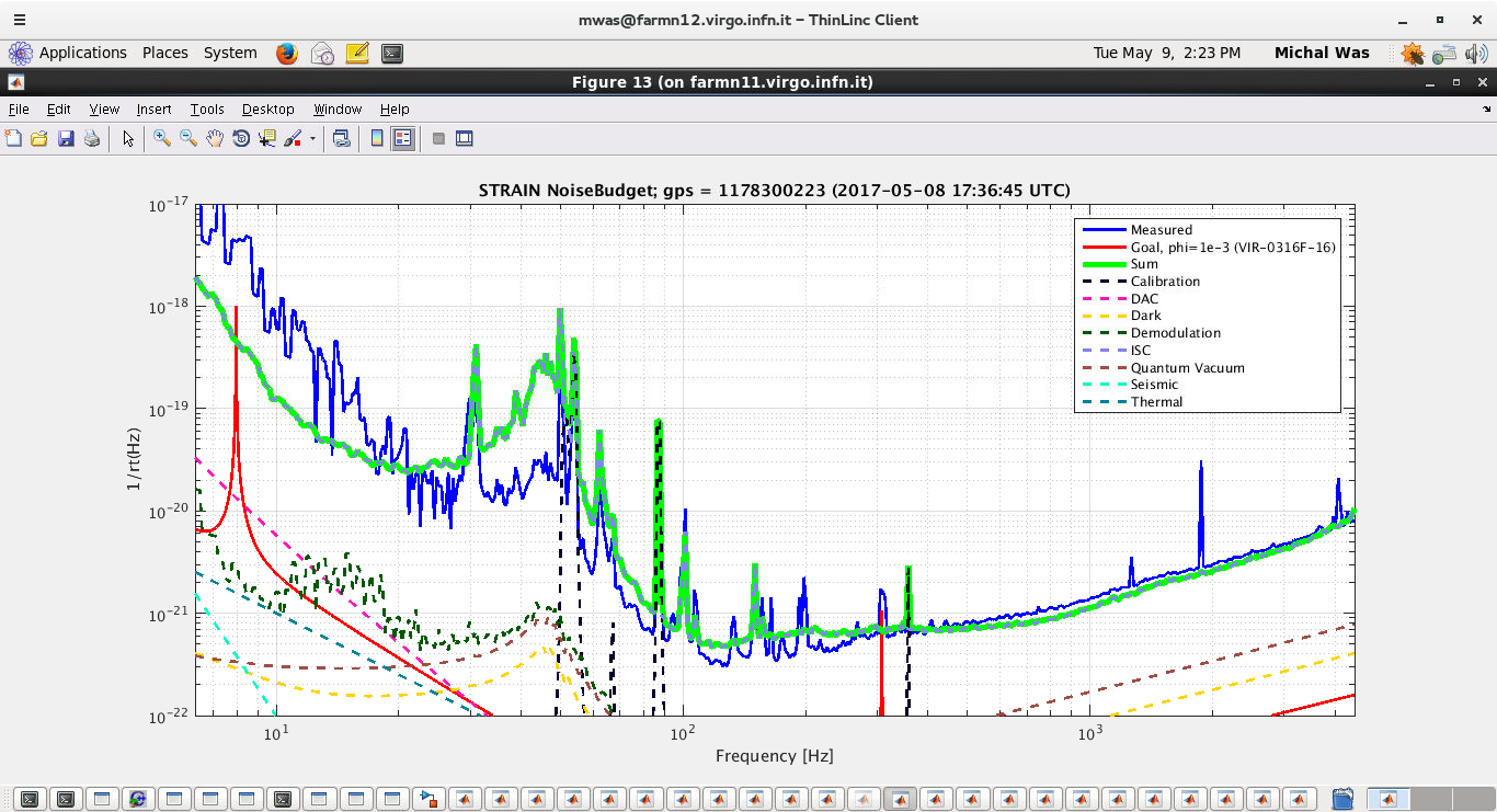
- in the end, we made a sensing noise injection, in order to have another evaluation of the UGF of the loop; the injection started at GPS = 1178300223 and it lasted 300 s. The UGF appears to be around 7 kHz, which is consistent with the 'mean value' that the online monitor suggests.